EP0188077A1 - Zahnriemenspanner mit gedämpfter, konstanter Federspannung und Vermeidung des Überspringens von Zähnen des Riemens - Google Patents
Zahnriemenspanner mit gedämpfter, konstanter Federspannung und Vermeidung des Überspringens von Zähnen des Riemens Download PDFInfo
- Publication number
- EP0188077A1 EP0188077A1 EP85308546A EP85308546A EP0188077A1 EP 0188077 A1 EP0188077 A1 EP 0188077A1 EP 85308546 A EP85308546 A EP 85308546A EP 85308546 A EP85308546 A EP 85308546A EP 0188077 A1 EP0188077 A1 EP 0188077A1
- Authority
- EP
- European Patent Office
- Prior art keywords
- coil spring
- pivoted structure
- pivoted
- clutch
- timing belt
- Prior art date
- Legal status (The legal status is an assumption and is not a legal conclusion. Google has not performed a legal analysis and makes no representation as to the accuracy of the status listed.)
- Granted
Links
- 230000002265 prevention Effects 0.000 title 1
- 238000013016 damping Methods 0.000 claims abstract description 31
- 230000002093 peripheral effect Effects 0.000 claims description 11
- 230000007423 decrease Effects 0.000 claims description 5
- 239000004957 Zytel Substances 0.000 claims description 4
- 229920006102 Zytel® Polymers 0.000 claims description 4
- 230000000694 effects Effects 0.000 claims description 3
- 230000003247 decreasing effect Effects 0.000 claims 1
- 230000007246 mechanism Effects 0.000 abstract description 6
- 230000000712 assembly Effects 0.000 description 4
- 238000000429 assembly Methods 0.000 description 4
- 238000009434 installation Methods 0.000 description 4
- 230000008901 benefit Effects 0.000 description 3
- 239000000463 material Substances 0.000 description 3
- 230000004048 modification Effects 0.000 description 3
- 238000012986 modification Methods 0.000 description 3
- 238000010276 construction Methods 0.000 description 2
- 230000003467 diminishing effect Effects 0.000 description 2
- 239000004033 plastic Substances 0.000 description 2
- 239000004677 Nylon Substances 0.000 description 1
- 230000009471 action Effects 0.000 description 1
- 230000008859 change Effects 0.000 description 1
- 238000006073 displacement reaction Methods 0.000 description 1
- 238000005516 engineering process Methods 0.000 description 1
- 230000007613 environmental effect Effects 0.000 description 1
- 239000007789 gas Substances 0.000 description 1
- 238000004519 manufacturing process Methods 0.000 description 1
- 229920001778 nylon Polymers 0.000 description 1
- 239000007787 solid Substances 0.000 description 1
- 108010007387 therin Proteins 0.000 description 1
Images

Classifications
-
- F—MECHANICAL ENGINEERING; LIGHTING; HEATING; WEAPONS; BLASTING
- F16—ENGINEERING ELEMENTS AND UNITS; GENERAL MEASURES FOR PRODUCING AND MAINTAINING EFFECTIVE FUNCTIONING OF MACHINES OR INSTALLATIONS; THERMAL INSULATION IN GENERAL
- F16H—GEARING
- F16H7/00—Gearings for conveying rotary motion by endless flexible members
- F16H7/08—Means for varying tension of belts, ropes or chains
-
- F—MECHANICAL ENGINEERING; LIGHTING; HEATING; WEAPONS; BLASTING
- F16—ENGINEERING ELEMENTS AND UNITS; GENERAL MEASURES FOR PRODUCING AND MAINTAINING EFFECTIVE FUNCTIONING OF MACHINES OR INSTALLATIONS; THERMAL INSULATION IN GENERAL
- F16H—GEARING
- F16H7/00—Gearings for conveying rotary motion by endless flexible members
- F16H7/08—Means for varying tension of belts, ropes or chains
- F16H7/10—Means for varying tension of belts, ropes or chains by adjusting the axis of a pulley
- F16H7/12—Means for varying tension of belts, ropes or chains by adjusting the axis of a pulley of an idle pulley
- F16H7/1209—Means for varying tension of belts, ropes or chains by adjusting the axis of a pulley of an idle pulley with vibration damping means
- F16H7/1218—Means for varying tension of belts, ropes or chains by adjusting the axis of a pulley of an idle pulley with vibration damping means of the dry friction type
-
- F—MECHANICAL ENGINEERING; LIGHTING; HEATING; WEAPONS; BLASTING
- F16—ENGINEERING ELEMENTS AND UNITS; GENERAL MEASURES FOR PRODUCING AND MAINTAINING EFFECTIVE FUNCTIONING OF MACHINES OR INSTALLATIONS; THERMAL INSULATION IN GENERAL
- F16H—GEARING
- F16H7/00—Gearings for conveying rotary motion by endless flexible members
- F16H7/08—Means for varying tension of belts, ropes or chains
- F16H2007/0802—Actuators for final output members
- F16H2007/081—Torsion springs
-
- F—MECHANICAL ENGINEERING; LIGHTING; HEATING; WEAPONS; BLASTING
- F16—ENGINEERING ELEMENTS AND UNITS; GENERAL MEASURES FOR PRODUCING AND MAINTAINING EFFECTIVE FUNCTIONING OF MACHINES OR INSTALLATIONS; THERMAL INSULATION IN GENERAL
- F16H—GEARING
- F16H7/00—Gearings for conveying rotary motion by endless flexible members
- F16H7/08—Means for varying tension of belts, ropes or chains
- F16H7/0829—Means for varying tension of belts, ropes or chains with vibration damping means
- F16H2007/084—Means for varying tension of belts, ropes or chains with vibration damping means having vibration damping characteristics dependent on the moving direction of the tensioner
-
- F—MECHANICAL ENGINEERING; LIGHTING; HEATING; WEAPONS; BLASTING
- F16—ENGINEERING ELEMENTS AND UNITS; GENERAL MEASURES FOR PRODUCING AND MAINTAINING EFFECTIVE FUNCTIONING OF MACHINES OR INSTALLATIONS; THERMAL INSULATION IN GENERAL
- F16H—GEARING
- F16H7/00—Gearings for conveying rotary motion by endless flexible members
- F16H7/08—Means for varying tension of belts, ropes or chains
- F16H2007/0889—Path of movement of the finally actuated member
- F16H2007/0893—Circular path
Definitions
- This invention relates to belt tensioners and, more particularly, to improvements in belt tensioners for use with timing belts and the like.
- a timing belt trained about two cooperating timing belt pulleys is a well-known motion transmitting assembly which has economical advantages when compared with other types of assemblies such as sprocket wheel and chain assemblies or meshing gear assemblies. Because of these economical advantages, timing belts have been extensively used in automobile engines for transmitting the motion of the drive shaft to the cam shaft. In such an installation, the distance between the two shafts is fixed and, consequently, it is not possible to tension the timing belt by moving the two shafts apart. To accommodate tensioning, fixed idler pulleys are usually utilized. Such idler pulleys are usually mounted so as to provide a range of adjustment so as to readily permit installation and movement of the idler pulley into a fixed position for operation.
- the idler pulleys are spring urged so the fixed operation position can be determined by the spring tension applied. That is, the idler pulley is moved under spring pressure into tensioning engagement with the belt under a predetermined spring tension which determines the operating position of the idler pulley. Prior to operation, however, the idler pulley is bolted or otherwise fixed into the desired operation position.
- a fixed idler pulley even when initially installed, presents a compromise between a condition in which the belt is less than optimally tight or more than optimally tight. More than optimal tightness is presented upon operation following the initial installation by virtue of the increase in tension resulting from thermal expansion between the axes of the shafts.
- the belt When the engine is cold, the belt is less tight than when the engine has been at running temperature for a while. In the long run beyond the initial installation, as the belt is operated, the belt tension tends to reduce due to belt stretching and belt wear leading to a less than optimal tightness situation.
- Timing belt tensioning device which maintains a constant optimum operating tension on the timing belt at all times and, at the same time, handles peak loads, such as presented at engine shut off, in such a way as to eliminate the attendant danger of tooth disengagement.
- timing belt tensioning device which will fulfill the aforesaid need.
- this objective is obtained by providing a timing belt tensioning device which includes a fixed structure, a pivoted structure mounted with respect to the fixed structure for pivotal movement about a first axis between first and second limiting positions.
- a timing belt engaging pulley is rotatably carried by the pivot structure for rotational movement about a second axis parallel with the first axis.
- a spring is mounted between the fixed and pivoted structures for resiliently biasing the pivoted structure to move in a direction away from the first limiting position toward the second limiting position with a spring force that decreases as the pivotal structure is moved in a direction away from the first position toward the second position.
- a one-way clutch is provided between the fixed and pivoted structures for permitting pivotal movement of the pivoted structure in a direction toward the second limiting position and for limiting the pivotal movement of the pivoted structure in an opposite direction toward the first limiting position beyond a predetermined distance measured from the nearest position of the pivoted structure to the second limiting position.
- the predetermined distance has a maximum dimension such as to prevent loosening of the timing belt engaged by the pulley sufficient to allow disengagement of a tooth thereof with a tooth of a timing pulley and a minimum dimension such as to accommodate normal operating low amplitude movements and thermal expansion during operation.
- a damping arrangement is provided for damping the operating movements of the pivoted structure permitted by the one-way clutch.
- the tensioning device normally functions in a manner which will permit normal operating movements and thermal expansion.
- the timing belt during such movements is maintained under constant tension by the spring.
- the establishment of resonance is prevented by the damping means.
- the one-way clutch permits this normal operation but positively prevents a movement of the timing belt engaging pulley beyond a distance which would enable a timing belt tooth to disengage from a timing pulley tooth.
- both the limitation as to this distance as well as the constant belt tension is maintained as the timing belt tends to elongate due to operating time and wear.
- the spring is of the helical coil type and the one-way clutch is of the helical coil type disposed in surrounding relation to the helical coil of the spring.
- damping means any type of damping means may be provided, preferably the damping means is provided in accordance with the teachings of commonly assigned U.S. Patent No. 4,473,362.
- the specific example of the damping means provided is by friction surface sliding with a damping force which decreases as the pivoted structure is moved in a direction away from the first limiting position toward the second limiting position both throughout the overall range of operation engagement of the one-way clutch and the predetermined distance of normal operation beyond which the one way clutch is operable.
- Another object of the present invention is the provision of a tensioning device of the type described which is simple in construction, effective in operation and economical to manufacture.
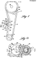
- an automotive engine timing belt and pulley system which includes a conventional flexible timing belt 12, having the usual teeth 14 on the interior periphery therof.
- the timing belt 12 is trained about a drive timing pulley 16 with exterior teeth 18 connected to the putput shaft 20 of the automotive engine and a driven timing pulley 22 with exterior teeth 24 connected to the cam shaft 26 of the automotive engine.
- a belt tensioning device mounted in operative relation to the timing belt is a belt tensioning device, generally indicated at 28, which embodies the principles of the present invention.
- the belt tensioning device 28 provides for the application of a substantially constant tension to the timing belt 12 of the system 10 over an extended period of time during which the belt tends to become longer.
- the solid line position of the belt tensioner illustrates the initial condition of the belt with the belt tensioner 28 in a minimum belt take-up position
- the dotted line position illustrates a maximum belt take-up position which may occur after extended use and the belt has been elongated.
- the belt tensioning device 28 of the present invention includes a fixed structure 30 which is adapted to be secured to a bracket plate 32 or the like in a stationary position with respect to the engine block.
- the belt tensioning device 28 also includes a pivoted structure 34 which is mounted with respect to the fixed structure 30 for pivotal movements about a fixed first axis between the first and second limiting positions.
- the pivoted structure 34 carries a timing belt engaging pulley 36 for rotational movement about a second axis parallel with the first axis.
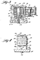
- a coil spring 38 (Figure 3) is mounted between the fixed structure 30 and pivoted structure 32 for resiliently biasing the latter to move in a direction away from the first limiting position thereof toward the second limiting position with a spring force which decreases as the pivoted structure is moved in a direction away from the first position toward the second position.
- the second position of the belt tensioner 28 corresponds generally with the dotted line position shown in Figure 1.
- the belt tensioning device 28 also includes a one-way clutch mechanism, generally indicated at 40, for permitting pivotal movement of the pivoted structure 34 in a direction toward the second limiting position and for limiting the pivotal movement of the pivoted structure 34 in an opposite direction toward the first limiting position beyond a predetermined distance measured from the nearest position of the pivoted structure to the second limiting position.
- the predetermined distance has a maximum dimension such as to prevent loosening of the timing belt 12 engaged by the pulley 36 sufficient to allow disengagement of a tooth 14 thereof with a tooth 18 or 24 of a timing pulley 16 or 22 and a minimum dimension such as to accommodate normal operating low amplitude vibrational movements and thermal expansion during operation.
- the damping is provided as a damping means, generally indicated at 42, constructed in accordance with the teachings of the aforesaid U.S. Patent No. 4,473,362, the disclosure of which is hereby incorporated by reference into the present specification.
- the fixed structure 30 may assume a variety of different configurations; however, as shown, it is made up of a rigid core member 44 having a radial flange portion 46 formed on one end thereof which, in turn, has an axial flange portion 48 extending from the outer edge thereof.
- Core member 44 is generally cylindrical in shape but has a slight frustoconical slope.
- a central opening 50 extends longitudinally therein which is threaded to receive a bolt 52 serving to detachably secure the fixed structure 30 to the bracket 32.
- opposite end of the core member 44 includes a reduced portion 54 formed with a square cross-sectional configuration.
- the rigid structure 30 also includes a circular end disk 56 having a square shaped central opening 58 shaped to receive the associated end portion 54 of the core member 44 which is then peened over to fix the connection.
- the flange portion 46 has a projection 60 formed thereon for engaging within an opening 62 formed within the bracket 32 so as to prevent the fixed structure 30 from moving with respect to the bracket about the axis of the bolt 52 and core member 44.
- the pivoted structure 34 includes a tubular inner portion 64 which is disposed in surrounding relation with the core member 44, an end wall portion 66 extending radially outwardly from one end of the inner tubular portion 64 and an outer tubular portion 68 extending axially from the outer end of radial end wall portion 66 in spaced surrounding relation with the inner tubular portion 64.
- Extending integrally from the free end of the exterior periphery of the outer tubular portion 68 is an arm portion 70.
- Pulley 36 is suitably journaled on the outer end of the arm portion 70 for rotational movement about a second axis which is parallel with respect to the first axis provided by the coil member 44.
- a conventional ball bearing assembly 72 is connected exteriorly with the interior of the pulley 36 and interiorly with a bolt 74 suitably threadedly engaged within the arm portion 70, as indicated at 76.
- the exterior periphery 78 of the fixed disk 56 has formed therein a notch 80.
- a lug 82 is formed integrally on the end wall portion 66 of the pivoted structure 34 and extends axially outwardly therefrom into a position within the notch 80 so that the limiting positions are determined by the engagement of the lug 82 with the wall surfaces of the disk 56 defining the opposite sides of the notch 80.
- the one-way clutch mechanism 40 is preferably of a type which includes a helical coil spring 84.
- the helical coil spring 84 is a tightly wound helical coil with its interior cylindrical configuration, when unstressed, being of a size to engage a cooperating exterior cylindrical clutch surface 86.
- the exterior cylindrical clutch surface 86 constitutes the exterior periphery of the outer tubular portion 68 of the pivoted structure 34.
- the one-way clutch serves to prevent pivotal movement of the pivoted structure 34 in a direction toward the first limiting position thereof beyond a predetermined distance. This predetermined distance is preferably provided by a lost motion connection between the clutch helical coil spring 84 and the fixed structure 30.
- the lost motion connection is provided by a notch 88 formed in the periphery 78 of the fixed disk 56.
- the adjacent end of the clutch helical coil spring 84 is bent axially outwardly, as indicated at 90, and disposed as to extend within the notch 88.
- the opposite end thereof is bent radially outwardly, as indicated at 92.
- the extent of the lost motion or the predetermined distance which lost motion provides has a maximum dimension such as to prevent loosening of the timing belt 12 engaged by the pulley 36 sufficient to allow disengagement of a tooth 14 with a tooth 18 or 24 or a timing pulley 16 or 22 and a minimum dimension such as to accommodate normal operating low amplitude movements and thermal expansion during operation.
- the end 92 of the clutch helical coil spring 84 normally does not perform any function in the operation of the one-way clutch but is provided to aid in assembly and disassembly.
- the extent of movement required to effect the releasing and fixing of the clutch engagement can be varied in accordance with known coil spring clutch technology. Where slippage is provided, this distance would be added to the distance provided by the lost motion connection in order to establish the predetermined distance. In the embodiment shown, the slippage distance is presumed to be equal to zero so that the distance of the lost motion provided by the lost motion connection between the clutch end 90 and the notch 88 determines the predetermined distance.
- the construction and operation of the damping means 42 is related both to the manner in which the pivoted structure 34 is mounted on the fixed structure 30 and the manner in which the spring 38 is connected between the pivoted and fixed structures.
- the spring 38 constitutes a torsional helical coil spring which is disposed within the annular space between the inner and outer tubular portions of the pivoted structure 34.
- One end of the torsional helical coil spring 38 is bent, as indicated at 94, to extend within a recess 96 formed in the interior surface of the end wall portion 66.
- the opposite end of the torsional helical coil spring 38 is bent, as indicated at 98, to extend radially outwardly through a 45° elongated opening 100 formed in the flange portion 48 of the fixed structure 30.
- a spring bearing member Mounted in sliding relation with the exterior periphery of the inner tubular portion 64 of the pivoted structure 34 is a spring bearing member, generally indicated at 102.
- the bearing member 102 is molded of a plastic material, a preferred plastic being Zytel .
- the bearing member 102 is formed with a cylindrical interior peripheral surface of a size to engage the exterior peripheral surface of the inner tubular portion 64.
- An annular flange 104 extends radially outwardly from the outer extremity of the bearing member 102 and is disposed in engagement with the inner surface of the end wall portion 46 of the fixed structure 30.
- Flange 4 may be formed at its outer periphery with an axially inwardly extending rib.
- the 45° inclination of opening 100 enables the end 98 of the spring 38 to be initially mounted therein at the axially inner end thereof so that the stressing of the spring during assembly tends to move the same axially outwardly into engagement with the flange 104.
- the engagement of the spring end 98 with the flange serves to depress or deform the flange or rib thereof so as to positively lock the bearing member 102 thereof against rotation with respect to the fixed structure 30.
- the arrangement does not positively prevent sliding movement of the bearing member 102 in a direction transverse to the axis of rotation.
- the damping mechanism 42 is in the form of a sleeve body 106 of a material such as Zytel 103HSL (nylon made by DuPont). Where Zytel is utilized as the material for the damping sleeve body 106 the damping action provided is essentially all sliding friction damping with the amount of solid damping by internal displacement being relatively insignificant.
- the pivoted structure 34 includes a cylindrical interior peripheral surface 108 which extends axially therethrough and defines the interior of the inner tubular portion 64.
- Damping sleeve body 106 has an exterior peripheral surface 110 of a size to enable the sleeve body to fit loosely within the pivoted structure surface 108.
- the damping sleeve body includes an interior peripheral surface which closely engages the exterior peripheral surface of the core member 44.
- One end of the damping sleeve body 106 has a flange 111 which seats against the adjacent surface of the pivoted structure 34 and the inner surface of the disk 56 of the fixed structure 30.
- the damping body 106 in its preferred form has a relatively tight fit at its inner periphery with the outer periphery of the core member 44, and a relatively loose fit between its exterior periphery and the interior periphery of the inner tubular portion 64 of the pivoted structure 34. Consequently, pivotal movement of the pivot structure 34 with respect to the fixed structure 30 between its limiting positions is basically accommodated by a sliding movement between the exterior peripheral surface 110 of the damping body 106 and the interior peripheral surface 108 of the inner tubular portion 64.
- the arrangement is such that the vibrational environment of the engine tends to cause the damping body 106 to assume a torsionally unstressed condition between the core member 44 and inner tubular portion 64 of the pivoted structure 34.
- the different positions of operation which the pivoted structure 34 assumes over an extended period of use by virtue of the belt wear and extension are readily accommodated.
- the normal operating position of the pivoted structure 34 moves more toward the maximum takeup second limiting position with the attendant diminishing of the torsional spring effect, there is a proportional diminishing of the force required to overcome the friction between the stress contacting surfaces of the inner tubular portion 64 and damping body 106.
- the remaining part of the exterior cylindrical clutch surface is provided by the exterior periphery 114 of a sleeve 116 slidably mounted within the recess 112.
- the lost motion connection is then provided between the sleeve 116 and the disk 56.
- the disk 56 has formed therin a plurality of annularly spaced notches 118, which, as shown, are three in number, being spaced equally annularly about the axis of the disk with the notch 80.
- the sleeve 116 is formed with a plurality of lugs 120 which extend axially outwardly therefrom into the notches 118.
Landscapes
- Engineering & Computer Science (AREA)
- General Engineering & Computer Science (AREA)
- Mechanical Engineering (AREA)
- Devices For Conveying Motion By Means Of Endless Flexible Members (AREA)
Applications Claiming Priority (2)
| Application Number | Priority Date | Filing Date | Title |
|---|---|---|---|
| US06/679,476 US4583962A (en) | 1984-12-07 | 1984-12-07 | Timing belt tensioner with damped constant spring tensioning and belt tooth disegagement prevention |
| US679476 | 1984-12-07 |
Publications (2)
| Publication Number | Publication Date |
|---|---|
| EP0188077A1 true EP0188077A1 (de) | 1986-07-23 |
| EP0188077B1 EP0188077B1 (de) | 1989-05-17 |
Family
ID=24727052
Family Applications (1)
| Application Number | Title | Priority Date | Filing Date |
|---|---|---|---|
| EP85308546A Expired EP0188077B1 (de) | 1984-12-07 | 1985-11-25 | Zahnriemenspanner mit gedämpfter, konstanter Federspannung und Vermeidung des Überspringens von Zähnen des Riemens |
Country Status (8)
| Country | Link |
|---|---|
| US (1) | US4583962A (de) |
| EP (1) | EP0188077B1 (de) |
| JP (1) | JPS61140661A (de) |
| KR (1) | KR930005966B1 (de) |
| BR (1) | BR8506117A (de) |
| DE (1) | DE3570270D1 (de) |
| ES (1) | ES8700735A1 (de) |
| MX (1) | MX165068B (de) |
Cited By (9)
| Publication number | Priority date | Publication date | Assignee | Title |
|---|---|---|---|---|
| GB2213557A (en) * | 1987-12-11 | 1989-08-16 | Skf Gmbh | A rotary assembly for use in a belt tensioning device |
| EP0364277A1 (de) * | 1988-10-13 | 1990-04-18 | Mitsuboshi Belting Ltd. | Kleinbauender, automatischer Riemenspanner |
| US4966571A (en) * | 1988-10-05 | 1990-10-30 | Casutchouc Manufacture et Plastiques | Internal combustion engine |
| EP0450620A1 (de) * | 1990-04-04 | 1991-10-09 | Litens Automotive GmbH | Automatischer Riemenspanner |
| EP0525512A1 (de) * | 1991-08-01 | 1993-02-03 | Continental Aktiengesellschaft | Vorrichtung zum Spannen von Treibriemen |
| GB2263150A (en) * | 1991-12-18 | 1993-07-14 | Ntn Toyo Bearing Co Ltd | Belt tension adjusting device |
| EP0575662A1 (de) * | 1992-06-25 | 1993-12-29 | Litens Automotive GmbH | Riemenspannvorrichtung |
| GB2279722A (en) * | 1993-07-10 | 1995-01-11 | Ford Motor Co | A drive-belt tensioner |
| DE102007044702A1 (de) * | 2007-09-19 | 2009-04-09 | Ab Skf | Lager |
Families Citing this family (84)
| Publication number | Priority date | Publication date | Assignee | Title |
|---|---|---|---|---|
| DE3528442C1 (de) * | 1985-08-08 | 1987-01-15 | Daimler Benz Ag | Spannvorrichtung |
| US4696663A (en) * | 1986-04-14 | 1987-09-29 | Dyneer Corporation | Belt tensioner |
| US4723934A (en) * | 1986-10-29 | 1988-02-09 | Dyneer Corporation | Belt tensioner |
| DE3637103A1 (de) * | 1986-10-31 | 1988-05-26 | Schaeffler Waelzlager Kg | Spannvorrichtung |
| DE3704521C2 (de) * | 1987-02-13 | 1996-09-12 | Skf Gmbh | Spannvorrichtung für Treibriemen |
| US4725260A (en) * | 1987-03-24 | 1988-02-16 | Litens Automotive Inc. | Belt tensioner with spring actuated band brake damping |
| US4897015A (en) * | 1987-05-15 | 1990-01-30 | Ade Corporation | Rotary to linear motion robot arm |
| DE3716571C1 (de) * | 1987-05-18 | 1989-01-12 | Werner Kotzab | Spannvorrichtung fuer Riemen und dgl.,insbesondere an Kraftfahrzeugmotoren |
| DE3728158A1 (de) * | 1987-05-18 | 1989-03-09 | Werner Kotzab | Spannvorrichtung fuer riemen u. dgl., insbesondere an kraftfahrzeugmotoren |
| JPS63308259A (ja) * | 1987-06-05 | 1988-12-15 | Mitsuboshi Belting Ltd | ベルト用オ−トテンショナ− |
| JPS6441754U (de) * | 1987-09-08 | 1989-03-13 | ||
| JPH0741957Y2 (ja) * | 1988-05-19 | 1995-09-27 | エヌティエヌ株式会社 | ベルトのオートテンショナ装置 |
| US4822322A (en) * | 1988-07-25 | 1989-04-18 | Ina Bearing Co., Inc. | Tensioning device for timing belt or chain in automotive engine applications |
| US4834694A (en) * | 1988-07-25 | 1989-05-30 | Ina Bearing Co., Inc. | Belt tensioning apparatus |
| FR2635043B1 (fr) * | 1988-08-05 | 1990-09-28 | Michelin & Cie | Appareil de fabrication d'un renforcement pour pneumatiques, ledit renforcement etant constitue a partir d'un seul fil |
| DE3905219A1 (de) * | 1988-09-28 | 1990-04-05 | Muhr & Bender | Riemenspannvorrichtung |
| US5195932A (en) * | 1988-10-13 | 1993-03-23 | Mitsuboshi Belting | Compact coil spring tensioner |
| JP2521525B2 (ja) * | 1988-12-29 | 1996-08-07 | 日本発条株式会社 | テンショナ― |
| US4917655A (en) * | 1989-03-01 | 1990-04-17 | Ina Bearing Co., Inc. | Self adjusting timing belt tensioner |
| GB2232741B (en) * | 1989-06-10 | 1992-12-23 | Unisys Corp | Belt tensioning apparatus |
| DE4001689C1 (en) * | 1990-01-22 | 1991-09-05 | Mercedes-Benz Aktiengesellschaft, 7000 Stuttgart, De | Tensioner for belt drive - has tension roller on lever with spiral torsion spring linked to housing |
| JPH0473646U (de) * | 1990-11-05 | 1992-06-29 | ||
| US5073148A (en) * | 1990-12-20 | 1991-12-17 | Gates Power Drive Products, Inc. | Tensioner with damping system |
| US5524725A (en) * | 1994-07-01 | 1996-06-11 | Arctco, Inc. | Automatic chain tension adjustor |
| US5591094A (en) * | 1995-11-01 | 1997-01-07 | The Gates Corporation | Tensioner with adjustable stop for power transmission belt |
| DE19813586B4 (de) * | 1998-03-27 | 2011-03-24 | Skf Gmbh | Spannvorrichtung für Treibriemen |
| JP2951321B1 (ja) * | 1998-06-26 | 1999-09-20 | ユニッタ株式会社 | オートテンショナ |
| CA2354273C (en) | 1998-12-08 | 2007-10-16 | Litens Automotive Partnership | Tensioner with self-limiting angular stroke |
| US6458055B1 (en) | 1999-04-12 | 2002-10-01 | Litens Automotive | Reversible tensioner |
| CA2368985C (en) | 1999-04-12 | 2007-03-20 | Litens Automotive | Timing belt tensioner with a backstop device with controlled one-way mechanism |
| US6375588B1 (en) | 1999-04-12 | 2002-04-23 | Litens Automotive Partnership | Tensioner with viscous coupled one way wrap spring anti-kickback clutch |
| DE19954481A1 (de) | 1999-11-12 | 2001-05-23 | Porsche Ag | Kettenführung für einen Steuerwellenantrieb einer Brennkraftmaschine sowie Verfahren zur Herstellung einer Kettenführung |
| WO2001040682A1 (en) | 1999-11-29 | 2001-06-07 | Litens Automotive Partnership | Timing belt tensioner having a floating backstop |
| US6565468B2 (en) | 1999-12-21 | 2003-05-20 | The Gates Corporation | Tensioner with damping mechanism |
| US6394247B1 (en) | 2000-05-31 | 2002-05-28 | Ntn Corporation | Complaint one way over-running clutch pulley |
| US6615809B1 (en) * | 2000-07-27 | 2003-09-09 | Allen L. Martin | External drive supercharger |
| US6605013B2 (en) * | 2000-09-15 | 2003-08-12 | Litens Automotive Partnership | Belt tensioner combination and a method of installing a tensioner on a belt |
| DE10131916A1 (de) * | 2001-07-05 | 2003-01-23 | Muhr & Bender Kg | Spanneinrichtung für Zugmittel, insbesondere Riemenspanneinrichtung |
| US6592482B2 (en) | 2001-10-22 | 2003-07-15 | The Gates Corporation | Tensioner |
| EP1451486B1 (de) * | 2001-12-05 | 2008-03-19 | Litens Automotive | Riemenspanner mit reibungsgesteuerter stopposition |
| DE10161534A1 (de) * | 2001-12-14 | 2003-06-18 | Ina Schaeffler Kg | Spannsystem für einen Zugmitteltrieb |
| US7175516B2 (en) | 2002-01-18 | 2007-02-13 | Memco | Poultry processing hub and belt assembly |
| US7118504B2 (en) * | 2002-02-07 | 2006-10-10 | Dayco Products, Llc | Hydraulic asymmetric damped belt tensioner |
| US6884194B2 (en) | 2002-02-07 | 2005-04-26 | Dayco Products, Llc | Hydraulic asymmetric damped belt tensioner |
| BR0313013A (pt) * | 2002-07-27 | 2005-08-09 | Xstream Security Solutions Ltd | Aparelho e método para criptografia e descriptografia |
| US7371199B2 (en) | 2003-09-13 | 2008-05-13 | Dayco Products, Llc | One-way clutched damper for automatic belt tensioner |
| JP4046684B2 (ja) * | 2003-12-26 | 2008-02-13 | 株式会社椿本チエイン | エンジン用テンショナ |
| US7901309B2 (en) * | 2004-09-01 | 2011-03-08 | Litens Automotive Partnership | Tensioner for a timing chain |
| CA2593119C (en) * | 2005-01-19 | 2014-07-08 | Litens Automotive Partnership | Timing belt tensioner |
| KR101273053B1 (ko) * | 2005-03-21 | 2013-06-10 | 리텐스 오토모티브 파트너쉽 | 재설치 형상부를 갖는 인장 장치 |
| WO2006105656A1 (en) * | 2005-04-08 | 2006-10-12 | Litens Automotive Partnership | Tensioner with molded arm |
| US20070249446A1 (en) * | 2006-03-29 | 2007-10-25 | Minchun Hao | Tensioner |
| DE102006017287B4 (de) * | 2006-04-12 | 2021-03-25 | Litens Automotive Gmbh | Spanner für einen Endlostrieb |
| US7678002B2 (en) * | 2006-08-31 | 2010-03-16 | Dayco Products, Llc | One-way clutched damper for automatic belt tensioner |
| US8162787B2 (en) * | 2006-08-31 | 2012-04-24 | Dayco Products, Llc | One-way clutched damper for automatic belt tensioner |
| US8038555B2 (en) * | 2006-08-31 | 2011-10-18 | Dayco Products, Llc | One-way clutched damper for automatic belt tensioner |
| DE102006047095B4 (de) * | 2006-10-05 | 2021-05-12 | Schaeffler Technologies AG & Co. KG | Spannvorrichtung |
| DE102006059550A1 (de) * | 2006-12-16 | 2008-06-19 | Schaeffler Kg | Spannvorrichtung für einen Zugmitteltrieb |
| US8784244B2 (en) * | 2008-04-30 | 2014-07-22 | Dayco Ip Holdings, Llc | Pulley with asymmetric torque-sensitive clutching |
| US7931552B2 (en) * | 2008-04-30 | 2011-04-26 | Dayco Products, Llc | Pulley with torque-sensitive clutching |
| US8529387B2 (en) * | 2008-04-30 | 2013-09-10 | Dayco Ip Holdings, Llc | Pulley with asymmetric torque-sensitive clutching |
| CA2738697C (en) | 2008-10-02 | 2017-01-03 | Litens Automotive Partnership | Compact tensioner with sustainable damping |
| US8403785B2 (en) | 2008-11-05 | 2013-03-26 | Dayco Ip Holdings, Llc | Clutched damper for a belt tensioner |
| KR101657726B1 (ko) * | 2008-11-17 | 2016-09-19 | 리텐스 오토모티브 파트너쉽 | 클러치 표면과 나선형 코일 클러치의 접속을 달성하기 위해 액추에이터를 포함하는 나선형 코일 클러치 조립체 |
| EP2672147B1 (de) * | 2009-03-30 | 2020-01-01 | TQ-Systems GmbH | Fahrzeug mit motorgetriebeeinheit |
| US11280394B2 (en) * | 2009-03-30 | 2022-03-22 | Tq-Systems Gmbh | Gear, motor-gear unit, vehicle, generator with a gear, and force transmitting element |
| US8888627B2 (en) | 2010-05-25 | 2014-11-18 | Dayco Ip Holdings, Llc | One-way damped over-arm tensioner |
| US8439781B2 (en) | 2010-06-22 | 2013-05-14 | Dayco Ip Holdings, Llc | Radial damping mechanism and use for belt tensioning |
| CN102985716B (zh) | 2010-06-25 | 2016-08-10 | 利滕斯汽车合伙公司 | 超速解耦器 |
| EP3865734A1 (de) | 2010-10-07 | 2021-08-18 | TQ-Systems GmbH | Getriebe, motorgetriebeeinheit, fahrzeug, generator mit einem getriebe und kraftübertragungselement |
| US20120316018A1 (en) * | 2011-06-08 | 2012-12-13 | Peter Ward | Tensioner |
| US20140287860A1 (en) * | 2011-10-26 | 2014-09-25 | Litens Automotive Partnership | Tensioner with damping structure made from two components with no rotational play therebetween |
| EP4400400A3 (de) | 2013-03-20 | 2025-01-22 | TQ-Systems GmbH | Harmonisches pinring-getriebe |
| US9290235B2 (en) * | 2013-06-18 | 2016-03-22 | Shimano Inc. | Bicycle derailleur |
| US9644716B2 (en) * | 2014-06-23 | 2017-05-09 | Sri International | Belt wave drives |
| DE102015211867A1 (de) * | 2015-06-25 | 2016-12-29 | Volkswagen Aktiengesellschaft | Anordnung eines drehbar gelagerten Elements an einem Gehäuse |
| DE102016122845A1 (de) | 2016-11-28 | 2018-05-30 | Tq-Systems Gmbh | Harmonisches Pinring-Getriebe, Drehmomentmessvorrichtung und Freilaufanordnung |
| WO2019046957A1 (en) | 2017-09-07 | 2019-03-14 | Litens Automotive Partnership | SINGLE-SPEED SINGLE-SPEED TORSION FREE WHEEL CUTTER |
| CN108190393B (zh) * | 2018-01-25 | 2024-07-30 | 宁夏天地奔牛实业集团有限公司 | 紧链装置及刮板输送机 |
| EP4234973A3 (de) | 2018-05-31 | 2023-10-25 | TQ-Systems GmbH | Getriebe mit zugmittel |
| US11142284B2 (en) * | 2018-07-30 | 2021-10-12 | Harley-Davidson Motor Company Group, LLC | Drive belt assembly for an electric vehicle |
| CN111594590B (zh) * | 2019-02-21 | 2024-05-17 | 舍弗勒投资(中国)有限公司 | 双向自张紧减速机构、p0系统及混合动力车辆 |
| IT202100014756A1 (it) * | 2021-06-07 | 2022-12-07 | Dayco Europe Srl | Tenditore con doppio sistema di smorzamento per una trasmissione di distribuzione a cinghia dentata |
| DE102022100471B4 (de) * | 2022-01-11 | 2025-07-17 | Bayerische Motoren Werke Aktiengesellschaft | Riementrieb zum Antreiben eines Kraftfahrzeugs, insbesondere eines Kraftrads, sowie Kraftfahrzeug, insbesondere Kraftrad |
Citations (5)
| Publication number | Priority date | Publication date | Assignee | Title |
|---|---|---|---|---|
| US1783987A (en) * | 1929-02-19 | 1930-12-09 | Morse Chain Co | Chain-adjusting device |
| DE1227302B (de) * | 1959-11-18 | 1966-10-20 | Renault | Kettenspanner |
| DE3045729A1 (de) * | 1976-09-25 | 1982-07-08 | Dr.Ing.H.C. F. Porsche Ag, 7000 Stuttgart | Spannvorrichtung fuer zahnriemen oder ketten bei brennkraftmaschinen |
| GB2090936A (en) * | 1981-01-12 | 1982-07-21 | Dyneer Corp | Belt tensioner |
| GB2102097A (en) * | 1981-07-08 | 1983-01-26 | Litens Automotive Inc | Belt tensioning devices |
Family Cites Families (2)
| Publication number | Priority date | Publication date | Assignee | Title |
|---|---|---|---|---|
| IT1137754B (it) * | 1981-07-23 | 1986-09-10 | Piaggio & C Spa | Dispositivo regolatore di tensione per cinghie dentate di trasmissione soggette a forti sbalzi di temperatura |
| US4472162A (en) * | 1982-04-16 | 1984-09-18 | Dyneer Corporation | Belt tensioner |
-
1984
- 1984-12-07 US US06/679,476 patent/US4583962A/en not_active Expired - Lifetime
-
1985
- 1985-11-25 DE DE8585308546T patent/DE3570270D1/de not_active Expired
- 1985-11-25 EP EP85308546A patent/EP0188077B1/de not_active Expired
- 1985-11-29 MX MX785A patent/MX165068B/es unknown
- 1985-11-30 KR KR1019850008999A patent/KR930005966B1/ko not_active Expired - Lifetime
- 1985-12-06 BR BR8506117A patent/BR8506117A/pt not_active IP Right Cessation
- 1985-12-06 ES ES549656A patent/ES8700735A1/es not_active Expired
- 1985-12-06 JP JP60273538A patent/JPS61140661A/ja active Pending
Patent Citations (5)
| Publication number | Priority date | Publication date | Assignee | Title |
|---|---|---|---|---|
| US1783987A (en) * | 1929-02-19 | 1930-12-09 | Morse Chain Co | Chain-adjusting device |
| DE1227302B (de) * | 1959-11-18 | 1966-10-20 | Renault | Kettenspanner |
| DE3045729A1 (de) * | 1976-09-25 | 1982-07-08 | Dr.Ing.H.C. F. Porsche Ag, 7000 Stuttgart | Spannvorrichtung fuer zahnriemen oder ketten bei brennkraftmaschinen |
| GB2090936A (en) * | 1981-01-12 | 1982-07-21 | Dyneer Corp | Belt tensioner |
| GB2102097A (en) * | 1981-07-08 | 1983-01-26 | Litens Automotive Inc | Belt tensioning devices |
Cited By (13)
| Publication number | Priority date | Publication date | Assignee | Title |
|---|---|---|---|---|
| GB2213557A (en) * | 1987-12-11 | 1989-08-16 | Skf Gmbh | A rotary assembly for use in a belt tensioning device |
| GB2213557B (en) * | 1987-12-11 | 1992-02-05 | Skf Gmbh | A rotary assembly |
| US4966571A (en) * | 1988-10-05 | 1990-10-30 | Casutchouc Manufacture et Plastiques | Internal combustion engine |
| EP0536809A1 (de) * | 1988-10-13 | 1993-04-14 | Mitsuboshi Belting Ltd. | Kleinbauender, automatischer Riemenspanner |
| EP0364277A1 (de) * | 1988-10-13 | 1990-04-18 | Mitsuboshi Belting Ltd. | Kleinbauender, automatischer Riemenspanner |
| EP0450620A1 (de) * | 1990-04-04 | 1991-10-09 | Litens Automotive GmbH | Automatischer Riemenspanner |
| EP0525512A1 (de) * | 1991-08-01 | 1993-02-03 | Continental Aktiengesellschaft | Vorrichtung zum Spannen von Treibriemen |
| GB2263150A (en) * | 1991-12-18 | 1993-07-14 | Ntn Toyo Bearing Co Ltd | Belt tension adjusting device |
| GB2263150B (en) * | 1991-12-18 | 1996-02-28 | Ntn Toyo Bearing Co Ltd | Belt tension adjusting device |
| EP0575662A1 (de) * | 1992-06-25 | 1993-12-29 | Litens Automotive GmbH | Riemenspannvorrichtung |
| GB2279722A (en) * | 1993-07-10 | 1995-01-11 | Ford Motor Co | A drive-belt tensioner |
| DE102007044702A1 (de) * | 2007-09-19 | 2009-04-09 | Ab Skf | Lager |
| DE102007044702B4 (de) * | 2007-09-19 | 2016-03-17 | Ab Skf | Lager |
Also Published As
| Publication number | Publication date |
|---|---|
| ES549656A0 (es) | 1986-10-16 |
| JPS61140661A (ja) | 1986-06-27 |
| KR930005966B1 (ko) | 1993-06-30 |
| MX165068B (es) | 1992-10-21 |
| BR8506117A (pt) | 1986-08-26 |
| KR860005181A (ko) | 1986-07-18 |
| US4583962A (en) | 1986-04-22 |
| DE3570270D1 (en) | 1989-06-22 |
| EP0188077B1 (de) | 1989-05-17 |
| ES8700735A1 (es) | 1986-10-16 |
Similar Documents
| Publication | Publication Date | Title |
|---|---|---|
| US4583962A (en) | Timing belt tensioner with damped constant spring tensioning and belt tooth disegagement prevention | |
| USRE34616E (en) | Belt tensioner with spring actuated band brake damping | |
| JP4535517B2 (ja) | 改良したオーバーラン・オルタネータ・デカプラーを備えるサーペンタインベルト駆動システム | |
| JP4508641B2 (ja) | テンショナ | |
| US4473362A (en) | Belt tensioner with variably proportional damping | |
| US5919107A (en) | Belt tensioner for motor vehicle | |
| JP5148475B2 (ja) | 再設置特徴付きテンショナ | |
| US6932731B2 (en) | Tensioner | |
| US5449328A (en) | Tensioning device for belt or chain drives | |
| JPH02225849A (ja) | 柔軟リンク装置による動力伝達のためのテンション装置 | |
| GB2348262A (en) | Tensioner lever | |
| CA2593116C (en) | Tensioner assembly with electronically controlled vibration clutch assembly | |
| US7540817B2 (en) | Tensioner with one-way clutch | |
| WO2005010401A1 (en) | Timing belt autotensioner with an anti-tooth skip mechanism | |
| JP3025167B2 (ja) | ベルトテンショナー | |
| EP2084425B1 (de) | Dämpfungsriemenscheibenanordnung | |
| EP0524431B1 (de) | Spannvorrichtung für Treibriemen | |
| CA2392560C (en) | Timing belt tensioner having a floating backstop | |
| JPH01295065A (ja) | ベルト用オートテンショナー |
Legal Events
| Date | Code | Title | Description |
|---|---|---|---|
| PUAI | Public reference made under article 153(3) epc to a published international application that has entered the european phase |
Free format text: ORIGINAL CODE: 0009012 |
|
| AK | Designated contracting states |
Kind code of ref document: A1 Designated state(s): DE FR GB IT |
|
| 17P | Request for examination filed |
Effective date: 19861205 |
|
| 17Q | First examination report despatched |
Effective date: 19870928 |
|
| ITF | It: translation for a ep patent filed | ||
| GRAA | (expected) grant |
Free format text: ORIGINAL CODE: 0009210 |
|
| AK | Designated contracting states |
Kind code of ref document: B1 Designated state(s): DE FR GB IT |
|
| REF | Corresponds to: |
Ref document number: 3570270 Country of ref document: DE Date of ref document: 19890622 |
|
| ET | Fr: translation filed | ||
| PLBE | No opposition filed within time limit |
Free format text: ORIGINAL CODE: 0009261 |
|
| STAA | Information on the status of an ep patent application or granted ep patent |
Free format text: STATUS: NO OPPOSITION FILED WITHIN TIME LIMIT |
|
| 26N | No opposition filed | ||
| ITTA | It: last paid annual fee | ||
| PGFP | Annual fee paid to national office [announced via postgrant information from national office to epo] |
Ref country code: FR Payment date: 19971112 Year of fee payment: 13 |
|
| PGFP | Annual fee paid to national office [announced via postgrant information from national office to epo] |
Ref country code: GB Payment date: 19971117 Year of fee payment: 13 |
|
| PGFP | Annual fee paid to national office [announced via postgrant information from national office to epo] |
Ref country code: DE Payment date: 19971201 Year of fee payment: 13 |
|
| PG25 | Lapsed in a contracting state [announced via postgrant information from national office to epo] |
Ref country code: GB Free format text: LAPSE BECAUSE OF NON-PAYMENT OF DUE FEES Effective date: 19981125 |
|
| GBPC | Gb: european patent ceased through non-payment of renewal fee |
Effective date: 19981125 |
|
| PG25 | Lapsed in a contracting state [announced via postgrant information from national office to epo] |
Ref country code: FR Free format text: LAPSE BECAUSE OF NON-PAYMENT OF DUE FEES Effective date: 19990730 |
|
| REG | Reference to a national code |
Ref country code: FR Ref legal event code: ST |
|
| PG25 | Lapsed in a contracting state [announced via postgrant information from national office to epo] |
Ref country code: DE Free format text: LAPSE BECAUSE OF NON-PAYMENT OF DUE FEES Effective date: 19990901 |