EP0188195A2 - Lageraufbau - Google Patents
Lageraufbau Download PDFInfo
- Publication number
- EP0188195A2 EP0188195A2 EP86100054A EP86100054A EP0188195A2 EP 0188195 A2 EP0188195 A2 EP 0188195A2 EP 86100054 A EP86100054 A EP 86100054A EP 86100054 A EP86100054 A EP 86100054A EP 0188195 A2 EP0188195 A2 EP 0188195A2
- Authority
- EP
- European Patent Office
- Prior art keywords
- staves
- bearing assembly
- set forth
- circumferentially spaced
- shell
- Prior art date
- Legal status (The legal status is an assumption and is not a legal conclusion. Google has not performed a legal analysis and makes no representation as to the accuracy of the status listed.)
- Granted
Links
- 239000003822 epoxy resin Substances 0.000 claims abstract description 22
- 229920000647 polyepoxide Polymers 0.000 claims abstract description 22
- 238000004519 manufacturing process Methods 0.000 claims abstract description 21
- 239000000463 material Substances 0.000 claims abstract description 21
- 239000004699 Ultra-high molecular weight polyethylene Substances 0.000 claims abstract description 13
- 229920000785 ultra high molecular weight polyethylene Polymers 0.000 claims abstract description 13
- 239000013536 elastomeric material Substances 0.000 claims abstract description 12
- 239000011152 fibreglass Substances 0.000 claims abstract description 12
- 239000004744 fabric Substances 0.000 claims description 23
- 125000006850 spacer group Chemical group 0.000 claims description 19
- 239000000835 fiber Substances 0.000 claims description 14
- 229920001971 elastomer Polymers 0.000 claims description 12
- 239000000806 elastomer Substances 0.000 claims description 6
- 230000002093 peripheral effect Effects 0.000 claims description 5
- XLYOFNOQVPJJNP-UHFFFAOYSA-N water Substances O XLYOFNOQVPJJNP-UHFFFAOYSA-N 0.000 claims description 5
- 239000004593 Epoxy Substances 0.000 claims description 3
- 239000000088 plastic resin Substances 0.000 claims 7
- 239000011347 resin Substances 0.000 claims 5
- 229920005989 resin Polymers 0.000 claims 5
- 229920002430 Fibre-reinforced plastic Polymers 0.000 claims 2
- 230000001464 adherent effect Effects 0.000 claims 2
- 239000011151 fibre-reinforced plastic Substances 0.000 claims 2
- 239000004698 Polyethylene Substances 0.000 claims 1
- -1 polyethylene Polymers 0.000 claims 1
- 229920000573 polyethylene Polymers 0.000 claims 1
- 238000007493 shaping process Methods 0.000 claims 1
- 239000011800 void material Substances 0.000 claims 1
- KAKZBPTYRLMSJV-UHFFFAOYSA-N Butadiene Chemical compound C=CC=C KAKZBPTYRLMSJV-UHFFFAOYSA-N 0.000 description 8
- 239000005060 rubber Substances 0.000 description 6
- UQMRAFJOBWOFNS-UHFFFAOYSA-N butyl 2-(2,4-dichlorophenoxy)acetate Chemical compound CCCCOC(=O)COC1=CC=C(Cl)C=C1Cl UQMRAFJOBWOFNS-UHFFFAOYSA-N 0.000 description 4
- 229920001577 copolymer Polymers 0.000 description 3
- 238000000034 method Methods 0.000 description 3
- 230000004048 modification Effects 0.000 description 3
- 238000012986 modification Methods 0.000 description 3
- 229920003023 plastic Polymers 0.000 description 3
- 239000002759 woven fabric Substances 0.000 description 3
- NLHHRLWOUZZQLW-UHFFFAOYSA-N Acrylonitrile Chemical compound C=CC#N NLHHRLWOUZZQLW-UHFFFAOYSA-N 0.000 description 2
- PPBRXRYQALVLMV-UHFFFAOYSA-N Styrene Chemical compound C=CC1=CC=CC=C1 PPBRXRYQALVLMV-UHFFFAOYSA-N 0.000 description 2
- 230000000712 assembly Effects 0.000 description 2
- 238000000429 assembly Methods 0.000 description 2
- 239000011248 coating agent Substances 0.000 description 2
- 238000000576 coating method Methods 0.000 description 2
- 230000005484 gravity Effects 0.000 description 2
- 239000007788 liquid Substances 0.000 description 2
- 230000001050 lubricating effect Effects 0.000 description 2
- 239000004033 plastic Substances 0.000 description 2
- 239000004848 polyfunctional curative Substances 0.000 description 2
- 230000000717 retained effect Effects 0.000 description 2
- 229910001369 Brass Inorganic materials 0.000 description 1
- 229920002943 EPDM rubber Polymers 0.000 description 1
- 229920000181 Ethylene propylene rubber Polymers 0.000 description 1
- 244000043261 Hevea brasiliensis Species 0.000 description 1
- 229920000459 Nitrile rubber Polymers 0.000 description 1
- 239000005062 Polybutadiene Substances 0.000 description 1
- 238000005299 abrasion Methods 0.000 description 1
- 150000001336 alkenes Chemical class 0.000 description 1
- 125000005250 alkyl acrylate group Chemical group 0.000 description 1
- 150000001412 amines Chemical class 0.000 description 1
- 239000010951 brass Substances 0.000 description 1
- 229920005549 butyl rubber Polymers 0.000 description 1
- 239000003795 chemical substances by application Substances 0.000 description 1
- 238000010276 construction Methods 0.000 description 1
- 230000000694 effects Effects 0.000 description 1
- HQQADJVZYDDRJT-UHFFFAOYSA-N ethene;prop-1-ene Chemical group C=C.CC=C HQQADJVZYDDRJT-UHFFFAOYSA-N 0.000 description 1
- 239000012530 fluid Substances 0.000 description 1
- 230000009477 glass transition Effects 0.000 description 1
- 229920002681 hypalon Polymers 0.000 description 1
- 238000005461 lubrication Methods 0.000 description 1
- 238000003754 machining Methods 0.000 description 1
- 239000000155 melt Substances 0.000 description 1
- 238000000465 moulding Methods 0.000 description 1
- 229920003052 natural elastomer Polymers 0.000 description 1
- 229920001194 natural rubber Polymers 0.000 description 1
- JRZJOMJEPLMPRA-UHFFFAOYSA-N olefin Natural products CCCCCCCC=C JRZJOMJEPLMPRA-UHFFFAOYSA-N 0.000 description 1
- 229920001084 poly(chloroprene) Polymers 0.000 description 1
- 229920000058 polyacrylate Polymers 0.000 description 1
- 229920002857 polybutadiene Polymers 0.000 description 1
- 229920000642 polymer Polymers 0.000 description 1
- 239000013535 sea water Substances 0.000 description 1
- 229920002379 silicone rubber Polymers 0.000 description 1
- 239000000126 substance Substances 0.000 description 1
- 239000000725 suspension Substances 0.000 description 1
Images

Classifications
-
- F—MECHANICAL ENGINEERING; LIGHTING; HEATING; WEAPONS; BLASTING
- F16—ENGINEERING ELEMENTS AND UNITS; GENERAL MEASURES FOR PRODUCING AND MAINTAINING EFFECTIVE FUNCTIONING OF MACHINES OR INSTALLATIONS; THERMAL INSULATION IN GENERAL
- F16C—SHAFTS; FLEXIBLE SHAFTS; ELEMENTS OR CRANKSHAFT MECHANISMS; ROTARY BODIES OTHER THAN GEARING ELEMENTS; BEARINGS
- F16C33/00—Parts of bearings; Special methods for making bearings or parts thereof
- F16C33/02—Parts of sliding-contact bearings
- F16C33/04—Brasses; Bushes; Linings
- F16C33/26—Brasses; Bushes; Linings made from wire coils; made from a number of discs, rings, rods, or other members
-
- B—PERFORMING OPERATIONS; TRANSPORTING
- B63—SHIPS OR OTHER WATERBORNE VESSELS; RELATED EQUIPMENT
- B63H—MARINE PROPULSION OR STEERING
- B63H23/00—Transmitting power from propulsion power plant to propulsive elements
- B63H23/32—Other parts
- B63H23/321—Bearings or seals specially adapted for propeller shafts
- B63H23/326—Water lubricated bearings
-
- F—MECHANICAL ENGINEERING; LIGHTING; HEATING; WEAPONS; BLASTING
- F16—ENGINEERING ELEMENTS AND UNITS; GENERAL MEASURES FOR PRODUCING AND MAINTAINING EFFECTIVE FUNCTIONING OF MACHINES OR INSTALLATIONS; THERMAL INSULATION IN GENERAL
- F16C—SHAFTS; FLEXIBLE SHAFTS; ELEMENTS OR CRANKSHAFT MECHANISMS; ROTARY BODIES OTHER THAN GEARING ELEMENTS; BEARINGS
- F16C17/00—Sliding-contact bearings for exclusively rotary movement
- F16C17/12—Sliding-contact bearings for exclusively rotary movement characterised by features not related to the direction of the load
- F16C17/14—Sliding-contact bearings for exclusively rotary movement characterised by features not related to the direction of the load specially adapted for operating in water
-
- F—MECHANICAL ENGINEERING; LIGHTING; HEATING; WEAPONS; BLASTING
- F16—ENGINEERING ELEMENTS AND UNITS; GENERAL MEASURES FOR PRODUCING AND MAINTAINING EFFECTIVE FUNCTIONING OF MACHINES OR INSTALLATIONS; THERMAL INSULATION IN GENERAL
- F16C—SHAFTS; FLEXIBLE SHAFTS; ELEMENTS OR CRANKSHAFT MECHANISMS; ROTARY BODIES OTHER THAN GEARING ELEMENTS; BEARINGS
- F16C33/00—Parts of bearings; Special methods for making bearings or parts thereof
- F16C33/02—Parts of sliding-contact bearings
- F16C33/04—Brasses; Bushes; Linings
- F16C33/22—Sliding surface consisting mainly of rubber or synthetic rubber
-
- F—MECHANICAL ENGINEERING; LIGHTING; HEATING; WEAPONS; BLASTING
- F16—ENGINEERING ELEMENTS AND UNITS; GENERAL MEASURES FOR PRODUCING AND MAINTAINING EFFECTIVE FUNCTIONING OF MACHINES OR INSTALLATIONS; THERMAL INSULATION IN GENERAL
- F16C—SHAFTS; FLEXIBLE SHAFTS; ELEMENTS OR CRANKSHAFT MECHANISMS; ROTARY BODIES OTHER THAN GEARING ELEMENTS; BEARINGS
- F16C2220/00—Shaping
- F16C2220/28—Shaping by winding impregnated fibres
-
- F—MECHANICAL ENGINEERING; LIGHTING; HEATING; WEAPONS; BLASTING
- F16—ENGINEERING ELEMENTS AND UNITS; GENERAL MEASURES FOR PRODUCING AND MAINTAINING EFFECTIVE FUNCTIONING OF MACHINES OR INSTALLATIONS; THERMAL INSULATION IN GENERAL
- F16C—SHAFTS; FLEXIBLE SHAFTS; ELEMENTS OR CRANKSHAFT MECHANISMS; ROTARY BODIES OTHER THAN GEARING ELEMENTS; BEARINGS
- F16C2326/00—Articles relating to transporting
- F16C2326/30—Ships, e.g. propelling shafts and bearings therefor
Definitions
- This invention relates to a bearing assembly and more particularly to elastomeric journal bearing assemblies which are adapted for use in supporting marine propeller shafts.
- Elastomeric journal bearings have been found to be particularly suited for this purpose because of their exceptional ability to withstand the effects of corrosive fluids and to abrasion resulting from bits of foreign materials which are carried in suspension in the sea water or other liquids in -. which the shaft.and journal bearing assembly operates.
- Such elastomeric journal bearing assemblies have been made and are still being made with rigid metallic support members but the materials are more expensive and the manufacturing costs are higher.
- a further advantage of the elastomeric journal bearings is that since they operate in a liquid medium they are self lubricated and therefore highly desirable for marine use as for the stern propeller shaft journals.
- the present invention is directed to a new and improved bearing assembly and the method of making such assembly utilizing a novel combination of shell and replaceable staves wherein the plurality of circumferentially spaced staves with flat bearing members provides support for a rotating shaft.
- the invention employs a molding process wherein the individual staves have radially outwardly extending projections about which fabric impregnated with plastic is wrapped filling in the recesses between the projections as well as around the projections to make a cylindrical shell.
- the radial outward portion of the stave including the projection is made from ultra high molecular weight polyethylene such that after curing of the shell, the staves are freely removable since the plastic shell does not adhere or stick to the ultra high molecular weight polyethylene.
- This process is considerably less expensive than the corresponding use of a machined recess or dovetail groove as in a brass bushing to receive the dovetail projection of the bearing element.
- it is particularly advantageous to fabricate a bearing assembly wherein adjacent bearing elements have sufficient clearance between them to provide a water course for lubrication purposes while maintaining their precise position relative to adjacent bearing elements or staves.
- a unique advantage of this invention is that the removeable staves are used in building the rigid housing assuring precise fitting while reducing the cost of fabrication.
- the rigid outer shell can be machined to a precise outer diameter as the job requires thereby reducing inventory. Additional layers of fiberglass reinforced plastic can be molded onto the outer shell to increase the diameter of the outer shell.
- the bearing assembly is simple in construction and has the attributes of a machined bearing assembly.
- the present invention is directed to a new and improved bearing assembly having a rigid non-metallic outer shell supporting a plurality of circumferentially spaced staves which staves are trapezoid in cross section with means to interlock their connection to the shell.
- Each stave is constructed from a semi-rigid material such as an ultra high molecular weight polyethylene which is bonded to an inner strip of an elastomer.
- the staves are held in circumferentially spaced relationship by their individual rigid connection to the shell and held in axial alignment by end caps.
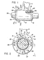
- FIG. 1 a longitudinally extending bearing housing 10 supported by a strut 11.
- Housing 10 has a pair of annular end sections 12, with each end section having a plurality of circumferentially spaced threaded bores 13.
- the housing 10 has a central bore 14 to accommodate a bearing unit to be described.
- the bearing unit has a plurality of circumferentially spaced staves 15 which include an inner trapezoidal shaped bearing element 17 made of an elastomeric material and an outer trapezoidal shaped bearing support element 18 that is made of an ultra high molecular weight polyethylene that is bonded to the elastomeric bearing element 17.
- Support bearing element 18 has a dovetail shaped projection 19 extending radially outwardly from its outermost surface and intergal with the element 18. Such dovetail projection 19 can be cast or machined thereon.
- An elastomer is defined as a substance that can be stretched at room temperatures to at least twice its original length and, after having been stretched and the stress removed, returns with force to approximately its original length in a short time. (See Glossary of Terms as prepared by ASTM Committee Dll on Rubber and Rubberlike Materials. Published by the American Society for Testing Materials).
- the elastomeric or rubber material that can be used can be any of the well known elastomers including for example natural rubber, copolymers of butadiene and acrylonitrile, copolymers of butadiene and styrene, copolymers of butadiene and alkyl acrylates, butyl rubber, olefin rubbers such as ethylene-propylene and EPDM rubber, fluorocarbons rubbers, fluoroisilicone rubbers, silicone rubbers, chlorosulfonated polyethylene, polyacrylates, polybutadiene, polychloroprene and the like.
- the bearing element 18 is made of ultra high molecular weight polyethylene having a melt flow index less than 0.15.
- an elongated flat sheet of elastomeric material such as nitrile rubbers such as polymers of butadiene and acrylonitrile is placed flat into a mold and vulcanized.
- a second sheet of ultra high molecular weight polyethylene is then molded into a flat sheet. Each of these individual sheets are cut into proper length or strips having proper angularly disposed sides to provide their trapezoidal cross sectional shape.
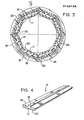
- the first and second sheets may be bonded together first and then cut into trapezoidal shapes such that the elastomeric inner bearing element 17 has a smaller base or bearing surface 20 than the bearing support element 18 supporting such bearing element 17, as seen in Figures 3 and.4.
- Such base 20 is a radially disposed inner bearing surface.
- The' dovetail 19 is machined into the outer portion of the outer bearing support element 18.
- Figure 3 shows the bearing elements or staves 15 with a clearance space between them to provide sufficient clearance to insure a proper flow of water for lubricating the rubber bearing surfaces 20.
- a plurality of staves are placed on a polygonal shaped mandrel and maintained thereon in any manner known in the art as by pulling a vacuum such that as the mandrel and staves are rotated a woven fabric of fiberglass designated 22 is wrapped or wound onto the outer peripheral surfaces of the staves. Such wrapping is done to fill the voids or recesses between adjacent staves. The wrapping is continued until a cylindrical shell 25 is formed. As the fabric is wrapped an epoxy resin is impregnated into the fabric such that as the overwrapping of the fabric continues the epoxy resin is built up and a dovetail groove 26 is formed in the shell 25.
- the epoxy resin can be sprayed or fed from a suitable reservoir or supply source onto the fabric and with the aid of a doctor blade a uniform coating is placed onto the fabric.
- the epoxy resin can be applied manually or by any known mechanical means.
- the number of layers of impregnated fiberglass that is applied around the outer surfaces of the circumferentially spaced staves 15 is determined by the desired size needed. After the epoxy resin has set, the outer surface can be machined to the desired diameter to form an outer cylindrical shell 25.
- a specific example of the epoxy resin useful in the present invention is one by the tradename "APCO” available from Applied Plastics Co., Inc. of 612 Franklin Avenue, El Segundo, CA 90245.
- the epoxy resin has a specific gravity of 1.165 and its accompanying curing agent or hardener has a specific gravity of 1.809.
- the epoxy resin has a shore D 25°C hardness of .84 with a glass transition temperature of 196°F.
- the viscosity of the epoxy resin is 2000 cps (1800 ⁇ 300); while the viscosity of the hardener is 410 cps (310 ⁇ 200).
- Another epoxy resin that can be used is one known as "EVERFIX EPOXY RESIN" having a density of 8.5 lbs. per gallon.
- the hardner used with such epoxy resin is a modified alaphatic amine adduct available through Fibre Glass-Ever Cost Co., Inc. 66700 Georgia road, Cincinnati, Ohio 45242.
- the stave like bearing elements 15 are replaceable since the epoxy will not adhere to the ultra high molecular weight polyethylene.
- the staves can be slid out of the grooves 26 and replaced in the bearing assembly.
- Such outer shell 25 and the staves 15 are located within the central bore 14 of housing 10, with the inner peripheral surfaces of the staves 15 abutting the drive shaft 29.
- the staves 15 are shown with a clearance space between adjacent sides to assure ease of replacement and insure an adequate flow of water for lubricating purposes.
- the respective dovetails of the staves 15 prevents rotation of the staves within such shell 25.
- the conventional and expensive system of machining dove-tailed grooves into the outer supporting sleeve or shell is eliminated however the rigidity of the staves is maintained, permitting the staves to be replaced - easily.
- the staves 15 are retained within such central bore by a pair of semi-circular retainer rings 27 acting as retainer means mounted on the respective end sections 12 of the cylindrically shaped housing 10. Rings 27 have a plurality of circumferentially spaced bores which receive cap screws 28 which are threaded into the respective threaded bores 13 to thereby securely fasten the staves 15 on the housing 10 in place on the shaft 29.
- each of the circumferentially spaced staves have an inner trapezoidal shaped bearing element 30 made of an elastomeric material as in the first described embodiment, and an outer trapezoidal shaped bearing support element 31 made of an ultra high molecular weight polyethylene material that is bonded to the elastomeric bearing element 30.
- the cross sectional shape of the modified form of the invention eliminates the need of the dovetailed shaped projection 19 by utilizing a fiberglass-epoxy pre-form spacer 34.
- Each spacer 34 has a rectangular shaped body portion 35 in cross and a rounded head 36.
- the rectangular shaped body portion 35 is a longitudinally extending spacer element that separates adjacent staves while the arcuately shaped head 36 will permit the convenient forming of the shell by permitting the wrapping of the woven fabric of fiberglass around the periphery of the circumferentially spaced staves to form the outer bearing shell.
- the plurality of staves can be placed on a polygonal shaped mandrel separated by the spacers 34. The staves are maintained or held in place thereon as by pulling a vacuum thereon such that as the mandrel and staves are rotated a woven fabric of fiberglass designated 38 is wrapped or wound onto the outer peripheral surface of the staves and the spacers 34.
- epoxy resin is spread onto the fabric impregnating such fabric with the epoxy resin such that as the overwrapping of the fabric continues, the epoxy resin is built up and forms a shell 40.
- the epoxy resin can be sprayed or fed from a suitable reservoir or supply source onto the fabric and with the aid of a doctor blade, form a uniform coating onto the fabric.
- the epoxy resin can be applied manually or by any known mechanical means.
- the number of layers of impregnated fiberglass that is applied around the outer surface to form the shell 40 is determined by the desired size needed.
- the epoxy resin and fiberglass wrapping 38 on setting becomes integral with the circumferentially spaced spacers 34 with the spacers acting as abutment means.
- the outer surface can be machined to the desired diameter to form the outer rigid cylindrical shell, with the spacers 34 forming abutment means, guides or tapered grooves for retaining or locking the staves in place to prevent movement or rotation when in use.
- the tapered grooves between the spacers or abutment means 34 receive the trapezoidal shaped bearing support element 31 of the removable staves.
Landscapes
- Engineering & Computer Science (AREA)
- General Engineering & Computer Science (AREA)
- Mechanical Engineering (AREA)
- Chemical & Material Sciences (AREA)
- Combustion & Propulsion (AREA)
- Ocean & Marine Engineering (AREA)
- Moulding By Coating Moulds (AREA)
- Reinforced Plastic Materials (AREA)
- Sliding-Contact Bearings (AREA)
- Shafts, Cranks, Connecting Bars, And Related Bearings (AREA)
Applications Claiming Priority (2)
| Application Number | Priority Date | Filing Date | Title |
|---|---|---|---|
| US689109 | 1985-01-07 | ||
| US06/689,109 US4596471A (en) | 1985-01-07 | 1985-01-07 | Bearing assembly |
Publications (3)
| Publication Number | Publication Date |
|---|---|
| EP0188195A2 true EP0188195A2 (de) | 1986-07-23 |
| EP0188195A3 EP0188195A3 (en) | 1987-09-30 |
| EP0188195B1 EP0188195B1 (de) | 1990-10-31 |
Family
ID=24767083
Family Applications (1)
| Application Number | Title | Priority Date | Filing Date |
|---|---|---|---|
| EP86100054A Expired - Lifetime EP0188195B1 (de) | 1985-01-07 | 1986-01-03 | Lageraufbau |
Country Status (6)
| Country | Link |
|---|---|
| US (1) | US4596471A (de) |
| EP (1) | EP0188195B1 (de) |
| JP (1) | JPS61197812A (de) |
| CA (1) | CA1250878A (de) |
| DE (1) | DE3675222D1 (de) |
| MX (1) | MX163108B (de) |
Cited By (2)
| Publication number | Priority date | Publication date | Assignee | Title |
|---|---|---|---|---|
| DE19632331A1 (de) * | 1996-08-10 | 1998-02-12 | Teves Gmbh Alfred | Lageranordnung |
| CN104728260A (zh) * | 2014-12-22 | 2015-06-24 | 广州市研理复合材料科技有限公司 | 一种多层层合弹塑合金自液润滑轴承及其制造方法 |
Families Citing this family (19)
| Publication number | Priority date | Publication date | Assignee | Title |
|---|---|---|---|---|
| US4663810A (en) * | 1985-01-07 | 1987-05-12 | The B. F. Goodrich Company | Method for fabricating an elastomeric bearing assembly |
| US4677721A (en) * | 1985-10-02 | 1987-07-07 | The B. F. Goodrich Company | Method for fabricating an elastomeric bearing assembly |
| US4802430A (en) * | 1987-10-26 | 1989-02-07 | The B. F. Goodrich Company | Composite rudder seal |
| US4809631A (en) * | 1987-10-26 | 1989-03-07 | The B. F. Goodrich Company | Composite rudder seal |
| IL90123A (en) * | 1988-10-25 | 1992-01-15 | Ide Russell D | Hydrodynamic bearing and its production |
| US4913563A (en) * | 1988-11-07 | 1990-04-03 | Westinghouse Electric Corp. | Hydrodynamic pivoted pad bearing assembly for a reactor coolant pump |
| JPH073057Y2 (ja) * | 1988-12-27 | 1995-01-30 | 西川ゴム工業株式会社 | 超高分子量ポリエチレン軸受 |
| FR2657584B1 (fr) * | 1990-01-29 | 1995-03-03 | Jeanneau Const Nautique | Palier souple pour le support de la meche d'un gouvernail. |
| AU1634992A (en) * | 1991-08-01 | 1993-02-04 | B.F. Goodrich Company, The | Composite and fairwater structures for marine vessels |
| FR2712942B1 (fr) * | 1993-11-26 | 1996-02-02 | Clechet Minoterie E | Perfectionnement pour paliers de turbines hydrauliques. |
| EP0698744A4 (de) * | 1994-03-10 | 1996-07-31 | Enomoto Co Ltd | Schiebestab |
| JP3281977B2 (ja) * | 1996-07-16 | 2002-05-13 | オーツケミカル株式会社 | 水中軸受 |
| US7077573B2 (en) * | 2001-06-11 | 2006-07-18 | Tribotek, Inc. | Contact bearing |
| JP3908094B2 (ja) * | 2002-06-11 | 2007-04-25 | 松下電器産業株式会社 | 積層型金属化フィルムコンデンサの製造方法 |
| JP2007225116A (ja) * | 2007-03-09 | 2007-09-06 | Akio Uno | 在水部の軸受装置 |
| CN104141689B (zh) * | 2013-05-08 | 2018-07-27 | 美国圣戈班性能塑料公司 | 一种由层压制件制成的轴承及其制作方法 |
| CN104074871B (zh) * | 2014-06-06 | 2016-05-11 | 中国人民解放军海军工程大学 | 一种具备自动匀载功能的船舶水润滑艉轴承 |
| US10508682B2 (en) * | 2015-12-31 | 2019-12-17 | Moog Inc. | Composite torque tube end fitting attachment method |
| CN114101487B (zh) * | 2021-11-08 | 2024-06-25 | 宁波诚泰汽车部件有限公司 | 一种一次成型压扁与打凸的精冲装置及工艺方法 |
Family Cites Families (9)
| Publication number | Priority date | Publication date | Assignee | Title |
|---|---|---|---|---|
| US1885339A (en) * | 1928-09-20 | 1932-11-01 | Goodrich Co B F | Rubber bearing structure |
| US1895936A (en) * | 1928-10-31 | 1933-01-31 | Goodrich Co B F | Rubber shaft-bearing |
| US3023059A (en) * | 1957-08-16 | 1962-02-27 | Borg Warner | Marine bearing |
| FR1539500A (fr) * | 1966-10-11 | 1968-09-13 | Byron Jackson Inc | éléments en forme de nervure intérieure pour des paliers de machines marines |
| US3692375A (en) * | 1970-12-01 | 1972-09-19 | Textron Inc | Composite plastic bearing and method for making the same |
| US3993371A (en) * | 1974-07-22 | 1976-11-23 | The B. F. Goodrich Company | Thin rubber surfaced bearings |
| US3932004A (en) * | 1975-02-06 | 1976-01-13 | The B. F. Goodrich Company | Rubber bearing with non-metallic support member |
| US4570315A (en) * | 1983-03-07 | 1986-02-18 | The B. F. Goodrich Company | Method of making a bearing |
| US4473308A (en) * | 1983-08-22 | 1984-09-25 | The B. F. Goodrich Company | Bearing assembly |
-
1985
- 1985-01-07 US US06/689,109 patent/US4596471A/en not_active Expired - Fee Related
-
1986
- 1986-01-03 EP EP86100054A patent/EP0188195B1/de not_active Expired - Lifetime
- 1986-01-03 DE DE8686100054T patent/DE3675222D1/de not_active Expired - Fee Related
- 1986-01-06 CA CA000499053A patent/CA1250878A/en not_active Expired
- 1986-01-07 MX MX1170A patent/MX163108B/es unknown
- 1986-01-07 JP JP61000347A patent/JPS61197812A/ja active Pending
Cited By (3)
| Publication number | Priority date | Publication date | Assignee | Title |
|---|---|---|---|---|
| DE19632331A1 (de) * | 1996-08-10 | 1998-02-12 | Teves Gmbh Alfred | Lageranordnung |
| CN104728260A (zh) * | 2014-12-22 | 2015-06-24 | 广州市研理复合材料科技有限公司 | 一种多层层合弹塑合金自液润滑轴承及其制造方法 |
| CN104728260B (zh) * | 2014-12-22 | 2018-03-23 | 广州市研理复合材料科技有限公司 | 一种多层层合弹塑合金自液润滑轴承的制造方法 |
Also Published As
| Publication number | Publication date |
|---|---|
| CA1250878A (en) | 1989-03-07 |
| MX163108B (es) | 1991-08-27 |
| JPS61197812A (ja) | 1986-09-02 |
| DE3675222D1 (de) | 1990-12-06 |
| US4596471A (en) | 1986-06-24 |
| EP0188195B1 (de) | 1990-10-31 |
| EP0188195A3 (en) | 1987-09-30 |
Similar Documents
| Publication | Publication Date | Title |
|---|---|---|
| CA1250878A (en) | Bearing assembly | |
| EP0133962B1 (de) | Lageraufbau | |
| EP0035782B1 (de) | Lagervorrichtung und Verfahren zu deren Herstellung | |
| US3932004A (en) | Rubber bearing with non-metallic support member | |
| US4577379A (en) | Bearing assembly and method for assembling a bearing | |
| US6648510B2 (en) | SPA super demountable bearing | |
| US4663810A (en) | Method for fabricating an elastomeric bearing assembly | |
| AU725564B2 (en) | Partial arc bearing assembly and method of making the same | |
| US5980112A (en) | Water lubricated bearing | |
| EP0217295B1 (de) | Lageraufbau | |
| US4773771A (en) | Bearing assembly | |
| US4677721A (en) | Method for fabricating an elastomeric bearing assembly | |
| US4570315A (en) | Method of making a bearing | |
| EP0834030B1 (de) | Dichtungsring | |
| EP2616375A2 (de) | Wickelhülse für bahnmaterial | |
| US4344806A (en) | Method of making a bearing | |
| EP0225569B1 (de) | Verfahren zum Herstellen eines Lagerteils | |
| US6238093B1 (en) | Partial arc bearing assembly and method of making the same | |
| GB2125492A (en) | Fluid seals for marine propulsion shafting | |
| KR100636894B1 (ko) | 부분원호형베어링조립체,베어링조립체용베어링슬랩및베어링조립체의제조방법 | |
| NZ505482A (en) | A bearing assembly and housing in water lubricated propeller shaft |
Legal Events
| Date | Code | Title | Description |
|---|---|---|---|
| PUAI | Public reference made under article 153(3) epc to a published international application that has entered the european phase |
Free format text: ORIGINAL CODE: 0009012 |
|
| AK | Designated contracting states |
Kind code of ref document: A2 Designated state(s): DE FR GB SE |
|
| PUAL | Search report despatched |
Free format text: ORIGINAL CODE: 0009013 |
|
| RHK1 | Main classification (correction) |
Ipc: F16C 33/22 |
|
| AK | Designated contracting states |
Kind code of ref document: A3 Designated state(s): DE FR GB SE |
|
| 17P | Request for examination filed |
Effective date: 19880408 |
|
| 17Q | First examination report despatched |
Effective date: 19890414 |
|
| GRAA | (expected) grant |
Free format text: ORIGINAL CODE: 0009210 |
|
| AK | Designated contracting states |
Kind code of ref document: B1 Designated state(s): DE FR GB SE |
|
| PGFP | Annual fee paid to national office [announced via postgrant information from national office to epo] |
Ref country code: FR Payment date: 19901128 Year of fee payment: 6 |
|
| REF | Corresponds to: |
Ref document number: 3675222 Country of ref document: DE Date of ref document: 19901206 |
|
| ET | Fr: translation filed | ||
| PGFP | Annual fee paid to national office [announced via postgrant information from national office to epo] |
Ref country code: SE Payment date: 19901218 Year of fee payment: 6 |
|
| PGFP | Annual fee paid to national office [announced via postgrant information from national office to epo] |
Ref country code: GB Payment date: 19901224 Year of fee payment: 6 |
|
| PGFP | Annual fee paid to national office [announced via postgrant information from national office to epo] |
Ref country code: DE Payment date: 19910226 Year of fee payment: 6 |
|
| PLBE | No opposition filed within time limit |
Free format text: ORIGINAL CODE: 0009261 |
|
| STAA | Information on the status of an ep patent application or granted ep patent |
Free format text: STATUS: NO OPPOSITION FILED WITHIN TIME LIMIT |
|
| 26N | No opposition filed | ||
| PG25 | Lapsed in a contracting state [announced via postgrant information from national office to epo] |
Ref country code: GB Effective date: 19920103 |
|
| PG25 | Lapsed in a contracting state [announced via postgrant information from national office to epo] |
Ref country code: SE Effective date: 19920104 |
|
| GBPC | Gb: european patent ceased through non-payment of renewal fee | ||
| PG25 | Lapsed in a contracting state [announced via postgrant information from national office to epo] |
Ref country code: FR Effective date: 19920930 |
|
| PG25 | Lapsed in a contracting state [announced via postgrant information from national office to epo] |
Ref country code: DE Effective date: 19921001 |
|
| REG | Reference to a national code |
Ref country code: FR Ref legal event code: ST |
|
| EUG | Se: european patent has lapsed |
Ref document number: 86100054.5 Effective date: 19920806 |