EP0188224A2 - Appareil de séparation de liquides - Google Patents
Appareil de séparation de liquides Download PDFInfo
- Publication number
- EP0188224A2 EP0188224A2 EP86100181A EP86100181A EP0188224A2 EP 0188224 A2 EP0188224 A2 EP 0188224A2 EP 86100181 A EP86100181 A EP 86100181A EP 86100181 A EP86100181 A EP 86100181A EP 0188224 A2 EP0188224 A2 EP 0188224A2
- Authority
- EP
- European Patent Office
- Prior art keywords
- liquid separation
- liquid
- vessel
- elements
- separation apparatus
- Prior art date
- Legal status (The legal status is an assumption and is not a legal conclusion. Google has not performed a legal analysis and makes no representation as to the accuracy of the status listed.)
- Withdrawn
Links
Images


Classifications
-
- B—PERFORMING OPERATIONS; TRANSPORTING
- B01—PHYSICAL OR CHEMICAL PROCESSES OR APPARATUS IN GENERAL
- B01D—SEPARATION
- B01D63/00—Apparatus in general for separation processes using semi-permeable membranes
- B01D63/10—Spiral-wound membrane modules
- B01D63/12—Spiral-wound membrane modules comprising multiple spiral-wound assemblies
-
- B—PERFORMING OPERATIONS; TRANSPORTING
- B01—PHYSICAL OR CHEMICAL PROCESSES OR APPARATUS IN GENERAL
- B01D—SEPARATION
- B01D35/00—Filtering devices having features not specifically covered by groups B01D24/00 - B01D33/00, or for applications not specifically covered by groups B01D24/00 - B01D33/00; Auxiliary devices for filtration; Filter housing constructions
- B01D35/14—Safety devices specially adapted for filtration; Devices for indicating clogging
- B01D35/147—Bypass or safety valves
-
- B—PERFORMING OPERATIONS; TRANSPORTING
- B01—PHYSICAL OR CHEMICAL PROCESSES OR APPARATUS IN GENERAL
- B01D—SEPARATION
- B01D35/00—Filtering devices having features not specifically covered by groups B01D24/00 - B01D33/00, or for applications not specifically covered by groups B01D24/00 - B01D33/00; Auxiliary devices for filtration; Filter housing constructions
- B01D35/14—Safety devices specially adapted for filtration; Devices for indicating clogging
- B01D35/157—Flow control valves: Damping or calibrated passages
-
- B—PERFORMING OPERATIONS; TRANSPORTING
- B01—PHYSICAL OR CHEMICAL PROCESSES OR APPARATUS IN GENERAL
- B01D—SEPARATION
- B01D61/00—Processes of separation using semi-permeable membranes, e.g. dialysis, osmosis or ultrafiltration; Apparatus, accessories or auxiliary operations specially adapted therefor
- B01D61/02—Reverse osmosis; Hyperfiltration ; Nanofiltration
- B01D61/10—Accessories; Auxiliary operations
Definitions
- the present invention is directed to an improvement in a liquid separation apparatus which uses a liquid separation membrane technique. More particularly, the present invention relates to structure and technique which reduces a pressure loss when a source liquid passes through a plurality of liquid separation elements arranged in series within a separation vessel.
- the objectives of the present invention can be obtained by supplying a suitable quantity of the source liquid to each of the plurality of liquid separation elements that are arranged or loaded in series into a vessel.
- Liquid separation apparatuses which use a liquid separation membrane are well known in the art, as disclosed, for example, in Japanese Patent Publication Nos. 14216/1969 and 5431/1977.
- liquid separation elements In order to realize a liquid separation apparatus having higher economy, when using the apparatus in practice, it is preferred that the greatest possible number of liquid separation elements (hereinafter called simply the “elements”) be placed or arranged in series into one vessel to provide a liquid separation apparatus (hereinafter called simply the “module”).
- the liquid separation elements, or simply “elements” usually contain a separating means, such as membrane, and accompanying structure for separating water from a liquid, etc, as known the art.
- Fig. 9 is a schematic view showing the overall construction of an example of the prior art technique.
- Four elements 2 1 -2 4 are loaded in series into a vessel 1.
- a source liquid 8 is supplied into the vessel 1 by a pump 7 through an inlet piping arrangement 4.
- the gaps between the vessel 1 and the elements 2 1 - 2 4 are sealed by seal members 3 1 - 3 4 , respectively. Therefore, the source liquid first passes through the liquid separation membrane surface of the element 2 1 , and the pure liquid after the separation by the membrane is then taken out from the vessel 1 through a pure liquid take-out pipe 6.
- the remaining source liquid is supplied to the next element 2 2 , and the pure liquid obtained in the same way is taken out from the pure liquid take-out pipe 6. In this manner, multi-stage processing is conducted sequentially. Finally, the concentrated liquid is discharged outside the system by a concentrated liquid discharge pipe 5.
- the elements are disposed in series and each element is completely sealed with respect to the vessel. Therefore, a greater pressure is applied to elements which are closer to the source liquid introduction inlet, and the pressure drops at the elements closer to the final stage, so that the elements closer to the pure liquid take-out pipe 6 cannot function to their full capacity.
- This problem becomes very significant, particularly, when a high flex type membrane is used wherein a great quantity of water is to be treated under low pressure, especially under 10 kg/cm 2 .
- the conventional technique involves another problem in that the pressure loss can become very large, and the elements can undergo breakage.
- the present invention provides a structure and technique which places means, such as a bypass circuit or a short-pass circuit, within the apparatus.
- This means divides a source liquid and supplies a suitable quantity of source liquid to each of a plurality of liquid separation elements arranged in series in a vessel, thereby reducing the pressure loss, occurring in a conventional apparatus, when the source liquid passes through the liquid separation elements.
- the present invention also make the most of the separation capacity of all the elements by the providing a more uniform flow and/or pressure to each respecting element.
- the liquid separation apparatus in accordance with the present invention employs a construction using the membrane separating technique, and is constituted by loading a plurality of liquid separation elements in series into a vessel.
- the apparatus of the present invention is characterized by including means capable of diverting a portion of flow of liquid from one separation element to the next or adjacent downstream element.
- the expression “loading or arranging a plurality of liquid separation elements ("elements") in series” means an arbitrary number of such elements, so long as at least two elements are loaded or arranged in series.
- the expression “a means for diverting a portion of source liquid from one separation element into the next or adjacent downstream element” refers to means which assures that a portion of source liquid will not pass on or contact the surface of a separating means, i.e., a membrane, within the liquid separation element and that this portion of source liquid will flow into an adjacent downstream element.
- a portion of source liquid is not substantially separated by upstream element(s) or elements of upstream stage(s).
- flow directions are relative to the direction of flow of source liquid.
- element 2 2 is upstream of element 2 and downstream of element 2 1 .
- the diverted portion of source liquid may be the source liquid itself, or a liquid which has been diverted from membrane surface of an upstream element, or liquid which remains after separation in an upstream element.
- the means for diverting a portion of source liquid of the present invention can also function to divert portions of source liquid between separation stages, contain a number of elements. Such a means will function and can have a structure the same as that for diverting a portion of flow of liquid between elements, as described herein.
- the present invention is characterized in means capable of satisfactorily introducing such a portion of source liquid into downstream elements, ranging from the inlet means of the source liquid.
- means capable of satisfactorily introducing such a portion of source liquid into downstream elements ranging from the inlet means of the source liquid.
- Figs. 1 and 2 show one embodiment of the present invention, in which an opening 11 is formed on each seal member 15 existing between the vessel 1 and each element 2.
- Ordinary seal members in general, can be used as the seal member 15, and examples include a V-lip, an 0-ring, an X-ring, a A-packing, and the like.
- the opening 11 is from 0.5 to 5 cm 2 when tJIP diameter of the element is 200 mm.
- the open area of the opening naturally changes when the element diameter changes, and the number of openings 11 can be arbitrary selected.
- the opening preferably opens at a position spaced apart by at least 2 mm from the tip of the lip in order to maintain high strength and to keep the opening highly stable.
- a pipe of a metal or plastic may be placed into the opening. From a practical point of view. the diameter of the opening is from about 1 to about 5 mm.
- Such openings preferably have an open ratio increasing from elements or stages of elements arranged near the feed side of the source liquid of the vessel to the output of the vessel, so as to make the pressure loss across the vessel uniform.
- Fig. 3 shows another embodiment of the present invention, in which short-path passages (openings) 12, 13 are formed with in the element 2 itself.
- these short-path passages 12, 13 may be disposed at arbitrary portions of the element, they are preferably disposed at the rigid portions of the element, so as not to damage the separation membrane and in order to use it reliably for an extended period.
- the term "rigid portion” represents the portion to which the membrane is fixed, other frame portions, a U-seal holder, and so forth. Among them, the U-seal holder is particularly preferable because it is easy to work with.
- the size and number of the openings are the same as described above and can be varied to achieve the objectives of the present invention.
- Figs. 4 and 5 show still another embodiment of the present invention, wherein grooves 14 are formed on the inner wall of the vessel.
- the groove 14 may have an arbitrary shape such as a U-shape, V-shape, recessed groove, and the like.
- the size and number of the grooves are the same as those of the opening.
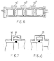
- Figs. 6 through 8 show still another embodiment of the present invention, wherein Fig. 6 shows an example in which by-pass pipes 16 (16 1 - 16 3 ) are disposed on the vessel.
- Fig. 6 shows the three bypass pipes
- the number of the by-pass pipes may be an arbitrary number of at least 1.
- a flow rate regulation mechanism is disposed for each by-pass pipe.
- Fig. 7 shows and example in which a valve 17 is disposed in by-pass pipe 16, as the flow rate regulation mechanism
- Fig. 8 shows an example in which an orifice 18 is disposed, as the flow regulation mechanism.
- the diameter of the by-pass pipe may be changed appropriately.
- Q is the quantity of the liquid passing through the by-pass pipe ( in units of : l/min) and AP is a pressure loss ( in units: kg/ cm 2 ).
- any type of separation membrane can be used in the present invention.
- membranes of a cellulose acetate type, a polyamide type, a cross-linked polyamine type, a crosslinked polyamine/polyether type, a crosslinked polyether type, a polyacrylonitride type, a polyether type, and a sulfonated polysulfone type These membranes may be suitably combined with one another.
- the membrane forms prepared from these membrane materials include an asymmetric membrane and a composite membrane.
- the membrane may include high and low retention membranes and combinations thereof.
- Element structures of the membrane that can be utilized for producing pure water apparatus include a spiral type, a hollow fiber type, a tubular type, a plate-and-frame type, and so forth.
- the present invention exhibits the following excellent effects.
- the present invention having by-pass circuits could reduce pressure loss in the module, and the quantity of water formation quantity could be improved by about 10% in comparison with the conventional technique at the same pressure.
- the quantity of water formation quantity can be improved by about 10% in comparison with the convention technique at the same pressure.
Landscapes
- Chemical & Material Sciences (AREA)
- Chemical Kinetics & Catalysis (AREA)
- Engineering & Computer Science (AREA)
- Water Supply & Treatment (AREA)
- Nanotechnology (AREA)
- Separation Using Semi-Permeable Membranes (AREA)
- Extraction Or Liquid Replacement (AREA)
- Degasification And Air Bubble Elimination (AREA)
Applications Claiming Priority (2)
| Application Number | Priority Date | Filing Date | Title |
|---|---|---|---|
| JP60000811A JPS61161104A (ja) | 1985-01-09 | 1985-01-09 | 液体分離装置 |
| JP811/85 | 1985-01-09 |
Publications (2)
| Publication Number | Publication Date |
|---|---|
| EP0188224A2 true EP0188224A2 (fr) | 1986-07-23 |
| EP0188224A3 EP0188224A3 (fr) | 1987-10-28 |
Family
ID=11484060
Family Applications (1)
| Application Number | Title | Priority Date | Filing Date |
|---|---|---|---|
| EP86100181A Withdrawn EP0188224A3 (fr) | 1985-01-09 | 1986-01-08 | Appareil de séparation de liquides |
Country Status (2)
| Country | Link |
|---|---|
| EP (1) | EP0188224A3 (fr) |
| JP (1) | JPS61161104A (fr) |
Cited By (13)
| Publication number | Priority date | Publication date | Assignee | Title |
|---|---|---|---|---|
| EP0414082A1 (fr) * | 1989-08-25 | 1991-02-27 | Günter Lauer | Elément filtrant pour le traitement d'un liquide |
| NL1005432C2 (nl) * | 1997-03-04 | 1998-09-07 | Stork Friesland Bv | Membraanfiltratiemodule en dergelijke modules omvattend membraanfiltratiesysteem. |
| NL1005430C2 (nl) * | 1997-03-04 | 1998-09-07 | Stork Friesland Bv | Membraanfiltratiemodule en dergelijke modules omvattend membraanfiltratiesysteem. |
| NL1005431C2 (nl) * | 1997-03-04 | 1998-09-07 | Stork Friesland Bv | Membraanfiltratiemodule en dergelijke modules omvattend membraanfiltratiesysteem. |
| EP0937493A3 (fr) * | 1998-02-20 | 2000-01-12 | X-Flow B.V. | Appareil de filtration |
| WO2003101594A1 (fr) * | 2002-05-29 | 2003-12-11 | Millipore Corporation | Cartouche a membrane de filtration enroulee en spirale a joint chevron |
| WO2003089101A3 (fr) * | 2002-04-15 | 2004-04-15 | Millipore Corp | Cartouche a membrane de filtration a enroulement spirale presentant une garniture d'etancheite chevron |
| US7396463B2 (en) | 2002-01-04 | 2008-07-08 | Enviro Holding A/S | Spiral wound membrane element and a process for preventing telescoping of the filter element |
| WO2008142190A1 (fr) * | 2007-05-23 | 2008-11-27 | Acciona Agua, S.A.U. | Dispositif destiné à la mesure de la perte de charge dans des conteneurs de membranes d'osmose inverse |
| WO2011088458A1 (fr) * | 2010-01-15 | 2011-07-21 | Hydranautics | Joint pour saumure conçu pour un dispositif de filtration |
| WO2013095874A1 (fr) * | 2011-12-21 | 2013-06-27 | General Electric Company | Manchon de dérivation axiale pour modules à membranes enroulées en spirale |
| US8728213B2 (en) | 2009-10-12 | 2014-05-20 | Toray Industries, Inc. | Radial split ring seal for filtration systems |
| US11369924B2 (en) | 2018-01-25 | 2022-06-28 | Toray Industries, Inc. | Membrane separation system and operation method for membrane separation system |
Family Cites Families (3)
| Publication number | Priority date | Publication date | Assignee | Title |
|---|---|---|---|---|
| US4064052A (en) * | 1976-06-28 | 1977-12-20 | Ladish Co. | Fractionator modules having lip seals |
| JPS57102202A (en) * | 1980-12-18 | 1982-06-25 | Toyobo Co Ltd | Fluid separator |
| JPS59147604A (ja) * | 1983-02-12 | 1984-08-24 | Nitto Electric Ind Co Ltd | 分離膜モジユ−ル |
-
1985
- 1985-01-09 JP JP60000811A patent/JPS61161104A/ja active Pending
-
1986
- 1986-01-08 EP EP86100181A patent/EP0188224A3/fr not_active Withdrawn
Cited By (22)
| Publication number | Priority date | Publication date | Assignee | Title |
|---|---|---|---|---|
| EP0414082A1 (fr) * | 1989-08-25 | 1991-02-27 | Günter Lauer | Elément filtrant pour le traitement d'un liquide |
| NL1005432C2 (nl) * | 1997-03-04 | 1998-09-07 | Stork Friesland Bv | Membraanfiltratiemodule en dergelijke modules omvattend membraanfiltratiesysteem. |
| NL1005430C2 (nl) * | 1997-03-04 | 1998-09-07 | Stork Friesland Bv | Membraanfiltratiemodule en dergelijke modules omvattend membraanfiltratiesysteem. |
| NL1005431C2 (nl) * | 1997-03-04 | 1998-09-07 | Stork Friesland Bv | Membraanfiltratiemodule en dergelijke modules omvattend membraanfiltratiesysteem. |
| EP0862943A1 (fr) * | 1997-03-04 | 1998-09-09 | Stork Friesland B.V. | Module de filtration à membranes et système de filtration comprenant de tels modules |
| EP0868941A1 (fr) * | 1997-03-04 | 1998-10-07 | Stork Friesland B.V. | Module de filtration à membranes et système de filtration à membranes comprenant de tels modules |
| US6251275B1 (en) | 1997-03-04 | 2001-06-26 | X-Flow B.V. | Membrane filtration module and membrane filtration system |
| EP0937493A3 (fr) * | 1998-02-20 | 2000-01-12 | X-Flow B.V. | Appareil de filtration |
| US7396463B2 (en) | 2002-01-04 | 2008-07-08 | Enviro Holding A/S | Spiral wound membrane element and a process for preventing telescoping of the filter element |
| WO2003089101A3 (fr) * | 2002-04-15 | 2004-04-15 | Millipore Corp | Cartouche a membrane de filtration a enroulement spirale presentant une garniture d'etancheite chevron |
| US7208088B2 (en) | 2002-05-29 | 2007-04-24 | Millipore Corporation | Spiral wound filtration membrane cartridge with chevron seal |
| WO2003101594A1 (fr) * | 2002-05-29 | 2003-12-11 | Millipore Corporation | Cartouche a membrane de filtration enroulee en spirale a joint chevron |
| WO2008142190A1 (fr) * | 2007-05-23 | 2008-11-27 | Acciona Agua, S.A.U. | Dispositif destiné à la mesure de la perte de charge dans des conteneurs de membranes d'osmose inverse |
| ES2332678A1 (es) * | 2007-05-23 | 2010-02-10 | Acciona Agua, S.A.U. | Dispositivos para la medici0n de la perdida de carga en contenedores de membranas de osmosis inversa. |
| ES2332678B1 (es) * | 2007-05-23 | 2011-01-26 | Acciona Agua, S.A.U. | Dispositivo para la medici0n de la perdida de carga en contenedores de membranas de osmosis inversa. |
| US8728213B2 (en) | 2009-10-12 | 2014-05-20 | Toray Industries, Inc. | Radial split ring seal for filtration systems |
| US9381469B2 (en) | 2009-10-12 | 2016-07-05 | Toray Industries, Inc. | Radial split ring seal for filtration systems |
| WO2011088458A1 (fr) * | 2010-01-15 | 2011-07-21 | Hydranautics | Joint pour saumure conçu pour un dispositif de filtration |
| US8388842B2 (en) | 2010-01-15 | 2013-03-05 | Hydranautics | Brine seal for a filtration device |
| WO2013095874A1 (fr) * | 2011-12-21 | 2013-06-27 | General Electric Company | Manchon de dérivation axiale pour modules à membranes enroulées en spirale |
| US8940168B2 (en) | 2011-12-21 | 2015-01-27 | General Electric Company | Axial bypass sleeve |
| US11369924B2 (en) | 2018-01-25 | 2022-06-28 | Toray Industries, Inc. | Membrane separation system and operation method for membrane separation system |
Also Published As
| Publication number | Publication date |
|---|---|
| JPS61161104A (ja) | 1986-07-21 |
| EP0188224A3 (fr) | 1987-10-28 |
Similar Documents
| Publication | Publication Date | Title |
|---|---|---|
| EP0188224A2 (fr) | Appareil de séparation de liquides | |
| US4861487A (en) | Spiral wound membrane modules and systems with improved feed spacer | |
| US6054051A (en) | Tangential-flow filtration system | |
| US7938956B2 (en) | Water purification system and method, and module for the system | |
| US3898158A (en) | Reverse osmosis separator unit | |
| US4988445A (en) | Spiral wound filtration system and method of utilizing same | |
| KR960033528A (ko) | 막장치 및 막처리장치 | |
| KR910009327A (ko) | 막분리 시스템 및 그 용법 | |
| PE39297A1 (es) | Planta de desalinizacion del agua | |
| EP2986849B1 (fr) | Appareil d'osmose | |
| US3922220A (en) | Permeable membrane separation device and method | |
| KR20040095203A (ko) | 필터 요소의 텔레스코핑을 막기 위한 프로세스와 나선형의감겨진 멤브레인 요소 | |
| US4299702A (en) | Liquid separation apparatus | |
| US20040182774A1 (en) | Spiral separation membrane element | |
| US6251271B1 (en) | Device for purifying a fluid | |
| EP0678326A1 (fr) | Dispositif de filtration par membrane, procédé de traitement d'un fluide par filtration par membrane et procédé de nettoyage d'un tel dispositif | |
| NL8103299A (nl) | Werkwijze voor het concentreren van oplossingen door middel van omgekeerde osmose. | |
| JP2000288356A (ja) | 逆浸透膜分離装置および造水方法 | |
| US4704205A (en) | Tubular membrane module wherein liquid flows around stay bolt | |
| KR930006396B1 (ko) | 직렬의 직교류 여과기 | |
| JP2852958B2 (ja) | 膜モジュールの運転方法 | |
| CA2241297A1 (fr) | Appareil de filtrage et de separation de milieux d'ecoulement a l'aide d'au moins une sortie permeable | |
| EP0103953B1 (fr) | Module de séparation comprenant des membranes de fibre creuse | |
| JPH0615270A (ja) | 逆浸透による造水装置 | |
| US7128092B2 (en) | Separating arrangement for treatment of fluids |
Legal Events
| Date | Code | Title | Description |
|---|---|---|---|
| PUAI | Public reference made under article 153(3) epc to a published international application that has entered the european phase |
Free format text: ORIGINAL CODE: 0009012 |
|
| AK | Designated contracting states |
Kind code of ref document: A2 Designated state(s): DE FR GB IT |
|
| PUAL | Search report despatched |
Free format text: ORIGINAL CODE: 0009013 |
|
| AK | Designated contracting states |
Kind code of ref document: A3 Designated state(s): DE FR GB IT |
|
| STAA | Information on the status of an ep patent application or granted ep patent |
Free format text: STATUS: THE APPLICATION IS DEEMED TO BE WITHDRAWN |
|
| 18D | Application deemed to be withdrawn |
Effective date: 19880429 |
|
| RIN1 | Information on inventor provided before grant (corrected) |
Inventor name: MURAGISHI, HIDEO Inventor name: NAOKATSU, KANAMARU Inventor name: IKADA, HIROYUKI |