EP0868941A1 - Module de filtration à membranes et système de filtration à membranes comprenant de tels modules - Google Patents
Module de filtration à membranes et système de filtration à membranes comprenant de tels modules Download PDFInfo
- Publication number
- EP0868941A1 EP0868941A1 EP98200567A EP98200567A EP0868941A1 EP 0868941 A1 EP0868941 A1 EP 0868941A1 EP 98200567 A EP98200567 A EP 98200567A EP 98200567 A EP98200567 A EP 98200567A EP 0868941 A1 EP0868941 A1 EP 0868941A1
- Authority
- EP
- European Patent Office
- Prior art keywords
- permeate
- housing
- membrane
- channels
- module according
- Prior art date
- Legal status (The legal status is an assumption and is not a legal conclusion. Google has not performed a legal analysis and makes no representation as to the accuracy of the status listed.)
- Withdrawn
Links
- 238000005374 membrane filtration Methods 0.000 title claims abstract description 29
- 239000012466 permeate Substances 0.000 claims abstract description 63
- 239000012528 membrane Substances 0.000 claims abstract description 56
- 239000007788 liquid Substances 0.000 claims abstract description 43
- 239000012141 concentrate Substances 0.000 claims abstract description 18
- 238000004891 communication Methods 0.000 claims abstract description 13
- 238000007599 discharging Methods 0.000 claims abstract description 3
- 239000000835 fiber Substances 0.000 claims description 14
- 239000004753 textile Substances 0.000 claims description 14
- 238000001914 filtration Methods 0.000 description 13
- 239000000356 contaminant Substances 0.000 description 8
- 238000000034 method Methods 0.000 description 2
- 239000002245 particle Substances 0.000 description 2
- 238000000926 separation method Methods 0.000 description 2
- 238000005054 agglomeration Methods 0.000 description 1
- 230000002776 aggregation Effects 0.000 description 1
- 230000009286 beneficial effect Effects 0.000 description 1
- 238000004140 cleaning Methods 0.000 description 1
- 238000005553 drilling Methods 0.000 description 1
- 230000002708 enhancing effect Effects 0.000 description 1
- 238000001125 extrusion Methods 0.000 description 1
- 230000002706 hydrostatic effect Effects 0.000 description 1
- 239000002184 metal Substances 0.000 description 1
- 238000001471 micro-filtration Methods 0.000 description 1
- 238000003801 milling Methods 0.000 description 1
- 230000004048 modification Effects 0.000 description 1
- 238000012986 modification Methods 0.000 description 1
- 238000001728 nano-filtration Methods 0.000 description 1
- 239000000047 product Substances 0.000 description 1
- 238000000746 purification Methods 0.000 description 1
- 238000001223 reverse osmosis Methods 0.000 description 1
- 238000007789 sealing Methods 0.000 description 1
- 239000013589 supplement Substances 0.000 description 1
- 238000000108 ultra-filtration Methods 0.000 description 1
Images


Classifications
-
- B—PERFORMING OPERATIONS; TRANSPORTING
- B01—PHYSICAL OR CHEMICAL PROCESSES OR APPARATUS IN GENERAL
- B01D—SEPARATION
- B01D63/00—Apparatus in general for separation processes using semi-permeable membranes
- B01D63/02—Hollow fibre modules
- B01D63/04—Hollow fibre modules comprising multiple hollow fibre assemblies
- B01D63/043—Hollow fibre modules comprising multiple hollow fibre assemblies with separate tube sheets
-
- B—PERFORMING OPERATIONS; TRANSPORTING
- B01—PHYSICAL OR CHEMICAL PROCESSES OR APPARATUS IN GENERAL
- B01D—SEPARATION
- B01D63/00—Apparatus in general for separation processes using semi-permeable membranes
- B01D63/02—Hollow fibre modules
-
- B—PERFORMING OPERATIONS; TRANSPORTING
- B01—PHYSICAL OR CHEMICAL PROCESSES OR APPARATUS IN GENERAL
- B01D—SEPARATION
- B01D63/00—Apparatus in general for separation processes using semi-permeable membranes
- B01D63/02—Hollow fibre modules
- B01D63/04—Hollow fibre modules comprising multiple hollow fibre assemblies
-
- B—PERFORMING OPERATIONS; TRANSPORTING
- B01—PHYSICAL OR CHEMICAL PROCESSES OR APPARATUS IN GENERAL
- B01D—SEPARATION
- B01D63/00—Apparatus in general for separation processes using semi-permeable membranes
- B01D63/06—Tubular membrane modules
-
- B—PERFORMING OPERATIONS; TRANSPORTING
- B01—PHYSICAL OR CHEMICAL PROCESSES OR APPARATUS IN GENERAL
- B01D—SEPARATION
- B01D63/00—Apparatus in general for separation processes using semi-permeable membranes
- B01D63/10—Spiral-wound membrane modules
- B01D63/107—Specific properties of the central tube or the permeate channel
-
- B—PERFORMING OPERATIONS; TRANSPORTING
- B01—PHYSICAL OR CHEMICAL PROCESSES OR APPARATUS IN GENERAL
- B01D—SEPARATION
- B01D63/00—Apparatus in general for separation processes using semi-permeable membranes
- B01D63/10—Spiral-wound membrane modules
- B01D63/12—Spiral-wound membrane modules comprising multiple spiral-wound assemblies
-
- B—PERFORMING OPERATIONS; TRANSPORTING
- B01—PHYSICAL OR CHEMICAL PROCESSES OR APPARATUS IN GENERAL
- B01D—SEPARATION
- B01D65/00—Accessories or auxiliary operations, in general, for separation processes or apparatus using semi-permeable membranes
-
- B—PERFORMING OPERATIONS; TRANSPORTING
- B01—PHYSICAL OR CHEMICAL PROCESSES OR APPARATUS IN GENERAL
- B01D—SEPARATION
- B01D65/00—Accessories or auxiliary operations, in general, for separation processes or apparatus using semi-permeable membranes
- B01D65/02—Membrane cleaning or sterilisation ; Membrane regeneration
-
- B—PERFORMING OPERATIONS; TRANSPORTING
- B01—PHYSICAL OR CHEMICAL PROCESSES OR APPARATUS IN GENERAL
- B01D—SEPARATION
- B01D2313/00—Details relating to membrane modules or apparatus
- B01D2313/08—Flow guidance means within the module or the apparatus
-
- B—PERFORMING OPERATIONS; TRANSPORTING
- B01—PHYSICAL OR CHEMICAL PROCESSES OR APPARATUS IN GENERAL
- B01D—SEPARATION
- B01D2321/00—Details relating to membrane cleaning, regeneration, sterilization or to the prevention of fouling
- B01D2321/02—Forward flushing
Definitions
- the invention relates to a membrane filtration module, comprising a housing, a semi-permeable membrane, which is accommodated in the housing and has a liquid side for the introduction of liquid to be filtered and a concentrate side opposite the liquid side, as well as a permeate chamber, which surrounds the membrane and is in communication with a permeate-discharge line for discharging permeate.
- a membrane filtration module of this kind is known in the art.
- a plurality of modules are often disposed in series in a single housing of the system or parallel to one another.
- the housing has (radial) feed openings on either side for the purpose of feeding in the liquid to be filtered.
- the modules are disposed in an accurately fitting manner in the housing, with spaces, into which the concentrate flows out, present between the modules. These spaces also serve as liquid-feed chambers for a subsequent module, as seen in the direction of flow.
- the perforated permeate-discharge line extends centrally through each module and through the spaces, those parts of the permeate-discharge line which are situated in the spaces not having any perforations, or else the perforations in those parts being sealed off.
- This discharge line emerges axially outwards on both sides of the housing of the system.
- a semi-permeable membrane such as a bundle of hollow fibres, a number of outside textile reinforced hollow fibre tubes or a membrane pattern wound into a spiral, is situated in the housing of the module.
- the permeate chamber is the chamber around the membrane, which is delimited by the housing.
- the membrane consists of hollow fibres or small outside textile reinforced hollow fibre tubes with a smooth outer surface
- the flow of liquid between the hollow fibres and/or outside textile reinforced hollow fibre tubes and/or through the perforations of the permeate-discharge line is inhibited as a result of the radial transport of permeate towards the central permeate discharge becoming increasingly strong towards the inside, resulting in a decrease in the filtering action of the system.
- there are features in known modules for enhancing the radial transport of permeate have the drawback that they are difficult to produce and take up space which could otherwise be used for fitting a membrane.
- the object of the present invention is to provide a membrane filtration module which makes it possible to ensure efficient discharge of permeate in a simple manner and to overcome the abovementioned drawbacks.
- the membrane filtration module of the type described above according to the invention is characterized in that the wall of the housing comprises one or more longitudinal channels which are closed towards the liquid side and the concentrate side and are in communication with the permeate chamber.
- the permeate can be discharged not only to the central permeate discharge but also towards the outer casing, where an additional collection and discharge of permeate is enabled.
- the radial transportation (directed from the outside inwards) of liquid through, for example, the bundle of fibres or outside textile reinforced hollow fibre tubes is considerably reduced, thus preventing the bundle from being pressed directly together and the flow of liquid from being impeded.
- the entire internal volume of the housing remains available for accommodating the membrane, so that the effective membrane surface is not reduced by the presence of the additional permeate channels.
- the housing is produced in the usual way from plastic or metal.
- the additional permeate channels may be internal wall channels communicating with the permeate chamber at certain positions, for example partly circumferential groove(s) produced in the inner wall of the housing. In this case flow of permeate to the permeate channels is allowed at said positions.
- the permeate channels can also be in the form of longitudinal recesses in the inner wall of the housing, which are open to the permeate chamber over their full length.
- the module of the invention comprises one such a channel positioned at the top of the module, which channel is connected to the permeate-discharge line via one or more connecting lines.
- This position of the channel allows for the easy removal of air contained in the module during the start up, as well as the removal of air contained in the liquid to be filtered during operation.
- the above connection lines are disposed at a distance from one another, viewed in the longitudinal direction of the module.
- the inner wall of the housing, as well as the inner wall of said channel is not flat, but instead thereof it is corrugated, e.g. having the shape of alternating radial ribs and recesses, or similarly roughened to provide an uneven surface such that the membrane is prevented from sealing by the inner wall.
- corrugated inner wall provides more strength than the "WAVIHOL" tube to be discussed hereinbelow.
- the cross-section area of the channel disposed at the top is the same as that of the permeate discharge line.
- the total cross-section area of the connecting lines is equal to the cross-section of the permeate-discharge line.
- a housing with internal wall channels made of plastic can be produced easily using suitable extrusion techniques (cf. for example NL-A-7500368), and can be processed further using simple techniques in order to form the connection between the channels and the interior.
- a product of this kind with channels which are closed towards the inside is already commercially available as a standard tube in standard dimensions suitable for use as a module housing.
- the cavities in the wall do not act as flow channels for the passage of a liquid, but rather they are provided in order to reduce the weight.
- An example is (PVC) tubes, which are marketed by Wavin under the brandname "WAVIHOL". The dimensions of these cavities are sufficiently large to serve as permeate channels.
- the shape, number and position of the channels in the wall of the housing are not critical. Round, square, rectangular, hexagonal and oval shapes are some of the possibilities.
- a plurality of channels are present, which are distributed evenly over the wall.
- the connection between the channels and the interior can easily be produced in the known tube, for example by milling open part of the inner wall or drilling into this wall as far as the channels.
- the channels are used as permeate channels, they are advantageously not in communication with the liquid side and concentrate side of the module, but rather are closed off towards the liquid side and concentrate side.
- these channels are in communication with a permeate-discharge line at one or both ends, advantageously at the end situated on the concentrate side.
- a central permeate-discharge line for the filtering action may even be superfluous.
- the channels are preferably in communication with a permeate-collection line, which is present outside the housing, via discharge openings in the outer wall of the housing.
- the presence of the central permeate-discharge line is advantageous for rinsing the module.
- the wall of the housing also comprises one or more rinsing channels with openings at both ends.
- This embodiment is particularly suitable for use in a membrane filtration system with filtration modules connected in series within one housing.
- rinsing liquid is usually introduced via the permeate-discharge line into the modules, rinsing back through the membrane and into the spaces, in order to remove deposited contaminants.
- one or more rinsing channels are arranged in the wall of the module housing itself, with the result that the whole of the interior of the housing is available for the semi-permeable membrane, so that the filtering action is not affected significantly by the presence of this rinsing channel or these rinsing channels.
- These rinsing channels form an open connection between the liquid side and the concentrate side of the module.
- these rinsing channels are already present and to form the permeate channels it is merely necessary to seal off a number of these channels at both ends, thereby producing connections between the cavities and the interior.
- rinsing channels which form an open connection (bypass) between the two sides of a module, ensure that the hydrostatic pressure on both sides is evened out without a loss of effective membrane surface and the working pressure in the membrane becomes higher. As a result, it is also possible to increase the length of the module, thus providing an economic advantage.
- a membrane can advantageously be used which comprises a first membrane component with a first diameter, as well as a second membrane component with a second diameter, the second diameter being greater than the first diameter.
- the membrane component with a relatively large diameter prevents the other membrane component from becoming tightly packed, and thus ensures the radial transportation of permeate.
- the membrane components of different diameters may be of the same type, for example fine and coarse hollow fibres or outside textile reinforced hollow fibre tubes with different diameters.
- the membrane component of small diameter and outside textile reinforced hollow fibre tubes and/or textile-reinforced capillaries as the second membrane component of relatively large diameter are also possible, for example hollow fibres as the membrane component of small diameter and outside textile reinforced hollow fibre tubes and/or textile-reinforced capillaries as the second membrane component of relatively large diameter.
- the diameter ratio between the first membrane component and the second membrane component is at least 1:2.
- the membrane comprises bundles of hollow fibres and outside textile reinforced hollow fibre tubes.
- a preferred position for the second membrane component is around the circumference of a central permeate-discharge line.
- the membrane component of relatively large diameter is (also) disposed in the region of the inner wall of the housing of the module. This latter embodiment is advantageously used if the wall of the housing comprises the abovementioned permeate channels. Arrangements of this kind can be realized in a technically relatively simple manner.
- the invention also relates to a membrane filtration system having a liquid feed and a permeate discharge, which comprises one or more membrane filtration modules according to the invention.
- Fig. 1 shows a diagrammatic section through a membrane filtration system 1.
- This system 1 comprises a housing 2 with radial liquid-feed openings 3 and 4 in the region of both its ends, which liquid-feed openings may also serve as, optionally intermittent, rinsing-liquid discharge openings.
- Three membrane filtration modules are disposed in an accurately fitting manner in the housing 2 of the system 1 illustrated, the two outer modules of which are denoted by reference numeral 5 and the central module of which is denoted by reference numeral 5'.
- Each module 5 comprises a housing 6, the structure of which will be explained in more detail below with reference to the other figures.
- a semi-permeable membrane 7, for example a bundle of hollow fibres or a number of outside textile reinforced hollow fibre tubes (illustrated by thin horizontal lines) is situated in the housing 6.
- the liquid side of the membrane is indicated by reference numeral 8, and the concentrate side by reference numeral 9.
- a liquid which is to be filtered and is fed via the liquid-feed openings 3 and 4
- the concentrate side by reference numeral 9.
- a liquid which is to be filtered and is fed via the liquid-feed openings 3 and 4
- the permeate flows out of the permeate chamber 10 and into a permeate-discharge line 11, which is partially provided with perforations.
- the permeate from all the modules 5 is collected in this line 11 and then discharged at one or both ends of the system 1.
- the concentrate flows out of the filter modules 5 into spaces 12 and 13 and then into the central membrane filtration module 5' for further separation, after which it is removed from the system 1 by being rinsed back via the concentrate discharge.
- the ends of the membrane 7 are fixed in the housing 6 in a manner known per se.
- the housing 6 of the modules 5 and 5' comprises one or more permeate channels 21, which are present in the wall 22 of the housing 6. These channels 21 are in open communication with the permeate chamber 10 and are closed off on the liquid side and concentrate side of the module, so that the liquid to be purified cannot flow directly into the permeate channels 21. See Fig. 2.
- this open connection is formed by a groove 23, which is arranged over the entire circumference of the inner wall 24 of the housing. If the flow of permeate through the permeate-discharge line is blocked or impeded, the permeate can flow out through the permeate channels 21.
- the permeate channels 21 open out into a connecting piece (not shown) which is coupled to the central permeate-discharge line.
- rinsing channels 31 (cf. Fig. 3), which, like the permeate channels 32, are present in the wall 33 of the housing 6 of the modules 5.
- These channels 31 of sufficiently large dimensions connect the spaces 12 and 13 to the feed chambers on the other side (liquid side) of the membrane filtration modules 5.
- the rinsing liquid introduced entrains the large contaminants through these channels 31, resulting in efficient cleaning of the membrane filtration system.
- the rinsing channels 31 and permeate channels 32 alternate.
- other configurations, such as in groups (Fig. 4) are also possible.
- FIG. 4 and 5 A further modification of the wall of the housing is illustrated in Fig. 4 and 5.
- the housing 6 comprises rinsing channels 41 in the wall 42, which connect the liquid side to the concentrate side, as well as permeate channels 43, which are closed at both ends, for example by a plug 44.
- the channels of each type are in groups in the wall 42.
- a groove 45 is provided in the inner wall 46 of the housing 6. In the situation illustrated, this groove 45 extends over half the internal circumference and has a depth which reaches the permeate channels 43.
- the permeate channels 43 are in communication, via discharge openings 47 in the outer wall 48 of the housing 6, with a permeate-collection line (not shown), which is positioned around the housing 6. Only one groove 45 is shown in Fig. 5. However, a person skilled in the art will understand that there will usually be a plurality of grooves distributed along the length of the housing 6.
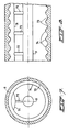
- Fig. 6 shows a cross-section through a further embodiment of a module according to the invention.
- a number of outside textile reinforced hollow fibre tubes 61 are disposed around the central permeate-discharge line 11, in order to ensure the radial transportation of liquid from bundles of hollow fibres 62 towards the permeate-discharge line 11.
- the wall of the module housing 6 also comprises permeate channels (not shown)
- outside textile reinforced hollow fibre tubes 63 are advantageously also disposed in the region of the inner wall of the housing 6, in order to ensure transportation of liquid towards these permeate channels.
- outside textile reinforced hollow fibre tubes 7a and 7c of large diameter contribute to the equalization of the pressure on either side of the module and to the removal of accumulated contaminants from the space by means of rinsing.
- the module according to the invention has one additional permeate channel 71 by means of a half cylindrical pipe, which is connected to the centrally disposed permeate-discharge line 11 via connecting lines 72.
- the inner wall of the housing 6 has a corrugated shape, thereby providing a number of circumferential grooves 73 alternated by ribs 74.
- an additional permeate channel can be produced in the corrugated inner surface of the housing in the form of a longitudinal groove by removing a part of the ribs 74 to the depth of the grooves 73.
- the longitudinal groove In order to direct the flow of permeate collected in the grooves 73 to a particular connecting line it is not necessary to modify all ribs 74, but instead thereof one could subdivide the longitudinal groove into several sections which are seperated from each other by an unmodified rib.
- the ribs could take the form of a spiral like an internal thread.
Landscapes
- Chemical & Material Sciences (AREA)
- Chemical Kinetics & Catalysis (AREA)
- Separation Using Semi-Permeable Membranes (AREA)
Applications Claiming Priority (2)
| Application Number | Priority Date | Filing Date | Title |
|---|---|---|---|
| NL1005430A NL1005430C2 (nl) | 1997-03-04 | 1997-03-04 | Membraanfiltratiemodule en dergelijke modules omvattend membraanfiltratiesysteem. |
| NL1005430 | 1997-03-04 |
Publications (1)
| Publication Number | Publication Date |
|---|---|
| EP0868941A1 true EP0868941A1 (fr) | 1998-10-07 |
Family
ID=19764526
Family Applications (1)
| Application Number | Title | Priority Date | Filing Date |
|---|---|---|---|
| EP98200567A Withdrawn EP0868941A1 (fr) | 1997-03-04 | 1998-02-23 | Module de filtration à membranes et système de filtration à membranes comprenant de tels modules |
Country Status (5)
| Country | Link |
|---|---|
| US (1) | US6251275B1 (fr) |
| EP (1) | EP0868941A1 (fr) |
| JP (1) | JPH10249172A (fr) |
| AU (1) | AU728630B2 (fr) |
| NL (1) | NL1005430C2 (fr) |
Cited By (4)
| Publication number | Priority date | Publication date | Assignee | Title |
|---|---|---|---|---|
| EP0937493A3 (fr) * | 1998-02-20 | 2000-01-12 | X-Flow B.V. | Appareil de filtration |
| WO2002041968A1 (fr) * | 2000-11-24 | 2002-05-30 | Membrane Concepts, S.L. | Corps pour filtres de membrane |
| EP1137478A4 (fr) * | 1998-11-02 | 2004-07-07 | Mg Generon | Modules d'alimentation a conduits lateraux avec canaux de flux de permeation |
| CN106232211A (zh) * | 2014-02-19 | 2016-12-14 | 巴斯夫欧洲公司 | 过滤元件 |
Families Citing this family (13)
| Publication number | Priority date | Publication date | Assignee | Title |
|---|---|---|---|---|
| JP3008886B2 (ja) * | 1997-04-24 | 2000-02-14 | 東洋紡績株式会社 | 中空糸型選択透過膜モジュール |
| US7316780B1 (en) | 1999-01-29 | 2008-01-08 | Pall Corporation | Range separation devices and processes |
| FR2815886B1 (fr) * | 2000-10-30 | 2002-12-06 | Hospal Ind | Faisceau de fibres creuses pour un appareil pour le traitement extracorporel du sang et du plasma et son procede de fabrication |
| DE10106722B4 (de) * | 2001-02-14 | 2008-11-06 | Fraunhofer-Gesellschaft zur Förderung der angewandten Forschung e.V. | Spezielles Hohlfaser-Membranmodul für den Einsatz in stark durch fouling beeinträchtigten Prozessen und seine Herstellung |
| DE10160855A1 (de) * | 2001-12-12 | 2003-06-26 | Schumacher Umwelt Trenntech | Filterelement und Filtervorrichtung für die Cross-Flow-Filtration |
| AU2002357338A1 (en) | 2002-01-09 | 2003-07-30 | Hydranautics | Methods for improving filtration performance of hollow fiber membranes |
| DE60331403D1 (de) * | 2002-12-26 | 2010-04-08 | Nipro Corp | Dialysator und dessen Herstellungsverfahren |
| AU2004275627B2 (en) * | 2003-09-29 | 2007-08-09 | Asahi Kasei Chemicals Corporation | External pressure type hollow fiber membrane module |
| JP2006255526A (ja) * | 2005-03-15 | 2006-09-28 | Fuji Electric Systems Co Ltd | 膜モジュールの洗浄方法 |
| US8043512B2 (en) * | 2008-04-11 | 2011-10-25 | Pall Corporation | Fluid treatment arrangements and methods |
| US8048315B2 (en) * | 2008-07-28 | 2011-11-01 | Pall Corporation | Fluid treatment arrangements and methods |
| KR200448226Y1 (ko) | 2009-06-30 | 2010-03-25 | 원현준 | 멤브레인 필터용 축봉 |
| US8945387B2 (en) | 2011-08-18 | 2015-02-03 | General Electric Company | Hollow fiber membrane module for use in a tubular pressure vessel |
Citations (13)
| Publication number | Priority date | Publication date | Assignee | Title |
|---|---|---|---|---|
| US3827564A (en) * | 1973-01-12 | 1974-08-06 | Culligan Int Co | Reverse osmosis membrane module |
| NL7415082A (en) * | 1974-11-19 | 1976-05-21 | Wafilin Bv | Membrane filter - of two membranes on a support spirally wound, with a labyrinthine liquid path between the windings |
| NL7905957A (nl) * | 1979-08-02 | 1980-09-30 | Wafilin Bv | Inrichting voor membraanfiltratie met buitenzijde afvoer. |
| EP0188224A2 (fr) * | 1985-01-09 | 1986-07-23 | Toray Industries, Inc. | Appareil de séparation de liquides |
| EP0203489A2 (fr) * | 1985-05-29 | 1986-12-03 | The Dow Chemical Company | Appareil à membranes sous forme de fibres creuses pourvu d'une enveloppe intérieure |
| JPS62250908A (ja) * | 1986-04-24 | 1987-10-31 | Asahi Chem Ind Co Ltd | 中空糸型濾過器 |
| JPS6393308A (ja) * | 1986-10-09 | 1988-04-23 | Asahi Chem Ind Co Ltd | 中空糸型濾過器 |
| EP0282355A2 (fr) * | 1987-03-13 | 1988-09-14 | BAXTER INTERNATIONAL INC. (a Delaware corporation) | Composition des fibres pour dialyseurs |
| EP0606933A1 (fr) * | 1993-01-14 | 1994-07-20 | Stork Friesland B.V. | Tube composite pour filtration par membrane |
| EP0668097A2 (fr) * | 1994-02-18 | 1995-08-23 | Dt Membranfilter Vertriebs Gmbh | Appareil de filtration et de séparation de fluides pourvu d'éléments filtrants sous forme de coussins à membranes |
| NL1003309C1 (nl) * | 1996-06-10 | 1996-07-24 | Rossmark Van Wijk En Boerma Wa | Membraanfiltersysteem en drukvat geschikt voor membraanfiltratie. |
| EP0761292A1 (fr) * | 1995-08-24 | 1997-03-12 | REHAU AG + Co | Membrane capillaire |
| WO1998020962A1 (fr) * | 1996-11-11 | 1998-05-22 | X-Flow B.V. | Module a membranes de filtration |
Family Cites Families (6)
| Publication number | Priority date | Publication date | Assignee | Title |
|---|---|---|---|---|
| US4045851A (en) * | 1974-09-20 | 1977-09-06 | Albany International Corporation | Method of fabrication of hollow filament separatory module |
| DE2525972C2 (de) * | 1975-06-11 | 1987-02-26 | Hoechst Ag, 6230 Frankfurt | Membranelement und Vorrichtung zur Durchführung der Membranfiltration |
| US4971689A (en) * | 1988-09-26 | 1990-11-20 | Burrows Bruce D | Reverse osmosis water purification system with improved pressure relief value |
| US5470468A (en) * | 1993-10-12 | 1995-11-28 | Koch Membrane Systems, Inc. | Spiral filtration module having bypass prevention flange |
| DK175061B1 (da) * | 1994-03-02 | 2004-05-10 | Apv Pasilac As | Membranfiltreringsarrangement |
| US5470469A (en) * | 1994-09-16 | 1995-11-28 | E. I. Du Pont De Nemours And Company | Hollow fiber cartridge |
-
1997
- 1997-03-04 NL NL1005430A patent/NL1005430C2/nl not_active IP Right Cessation
-
1998
- 1998-02-23 EP EP98200567A patent/EP0868941A1/fr not_active Withdrawn
- 1998-03-03 JP JP10050783A patent/JPH10249172A/ja active Pending
- 1998-03-03 US US09/033,885 patent/US6251275B1/en not_active Expired - Lifetime
- 1998-03-03 AU AU56405/98A patent/AU728630B2/en not_active Ceased
Patent Citations (14)
| Publication number | Priority date | Publication date | Assignee | Title |
|---|---|---|---|---|
| US3827564A (en) * | 1973-01-12 | 1974-08-06 | Culligan Int Co | Reverse osmosis membrane module |
| NL7415082A (en) * | 1974-11-19 | 1976-05-21 | Wafilin Bv | Membrane filter - of two membranes on a support spirally wound, with a labyrinthine liquid path between the windings |
| NL7905957A (nl) * | 1979-08-02 | 1980-09-30 | Wafilin Bv | Inrichting voor membraanfiltratie met buitenzijde afvoer. |
| EP0188224A2 (fr) * | 1985-01-09 | 1986-07-23 | Toray Industries, Inc. | Appareil de séparation de liquides |
| EP0203489A2 (fr) * | 1985-05-29 | 1986-12-03 | The Dow Chemical Company | Appareil à membranes sous forme de fibres creuses pourvu d'une enveloppe intérieure |
| JPS62250908A (ja) * | 1986-04-24 | 1987-10-31 | Asahi Chem Ind Co Ltd | 中空糸型濾過器 |
| JPS6393308A (ja) * | 1986-10-09 | 1988-04-23 | Asahi Chem Ind Co Ltd | 中空糸型濾過器 |
| EP0282355A2 (fr) * | 1987-03-13 | 1988-09-14 | BAXTER INTERNATIONAL INC. (a Delaware corporation) | Composition des fibres pour dialyseurs |
| EP0606933A1 (fr) * | 1993-01-14 | 1994-07-20 | Stork Friesland B.V. | Tube composite pour filtration par membrane |
| EP0668097A2 (fr) * | 1994-02-18 | 1995-08-23 | Dt Membranfilter Vertriebs Gmbh | Appareil de filtration et de séparation de fluides pourvu d'éléments filtrants sous forme de coussins à membranes |
| EP0761292A1 (fr) * | 1995-08-24 | 1997-03-12 | REHAU AG + Co | Membrane capillaire |
| NL1003309C1 (nl) * | 1996-06-10 | 1996-07-24 | Rossmark Van Wijk En Boerma Wa | Membraanfiltersysteem en drukvat geschikt voor membraanfiltratie. |
| WO1997047375A1 (fr) * | 1996-06-10 | 1997-12-18 | Usf Rossmark Waterbehandeling B.V. | Systeme de filtre membranaire |
| WO1998020962A1 (fr) * | 1996-11-11 | 1998-05-22 | X-Flow B.V. | Module a membranes de filtration |
Non-Patent Citations (2)
| Title |
|---|
| PATENT ABSTRACTS OF JAPAN vol. 012, no. 132 (C - 490) 22 April 1988 (1988-04-22) * |
| PATENT ABSTRACTS OF JAPAN vol. 012, no. 333 (C - 526) 8 September 1988 (1988-09-08) * |
Cited By (4)
| Publication number | Priority date | Publication date | Assignee | Title |
|---|---|---|---|---|
| EP0937493A3 (fr) * | 1998-02-20 | 2000-01-12 | X-Flow B.V. | Appareil de filtration |
| EP1137478A4 (fr) * | 1998-11-02 | 2004-07-07 | Mg Generon | Modules d'alimentation a conduits lateraux avec canaux de flux de permeation |
| WO2002041968A1 (fr) * | 2000-11-24 | 2002-05-30 | Membrane Concepts, S.L. | Corps pour filtres de membrane |
| CN106232211A (zh) * | 2014-02-19 | 2016-12-14 | 巴斯夫欧洲公司 | 过滤元件 |
Also Published As
| Publication number | Publication date |
|---|---|
| AU728630B2 (en) | 2001-01-11 |
| AU5640598A (en) | 1998-09-10 |
| US6251275B1 (en) | 2001-06-26 |
| NL1005430C2 (nl) | 1998-09-07 |
| JPH10249172A (ja) | 1998-09-22 |
Similar Documents
| Publication | Publication Date | Title |
|---|---|---|
| US6251275B1 (en) | Membrane filtration module and membrane filtration system | |
| KR100519690B1 (ko) | 개선된 미공성 막 여과 조립체 | |
| JP3008886B2 (ja) | 中空糸型選択透過膜モジュール | |
| US6190557B1 (en) | Spiral wound type membrane element, running method and washing method thereof | |
| CN111225732B (zh) | 集成膜模块架 | |
| US4707268A (en) | Hollow fiber potted microfilter | |
| EP1022052A2 (fr) | Elément de membrane enroulé en spirale et prcédés pour son opération et son lavage | |
| EP0396684A1 (fr) | Dispositif de filtration a ecoulement transversal et son procede de fabrication. | |
| TW201318689A (zh) | 用於一管狀壓力導管之中空纖維膜模組 | |
| US10576425B2 (en) | Unhoused filtration device and methods of use | |
| TW201302289A (zh) | 具有減少滲透壓損失之過濾裝置的中間連接器 | |
| EP0862943B1 (fr) | Module de filtration à membranes et système de filtration comprenant de tels modules | |
| US20040045890A1 (en) | Hollow fiber membrane cassette | |
| AU2002236864B2 (en) | Hollow fiber membrane cassette | |
| US20150021254A1 (en) | Filtration device | |
| US20010040128A1 (en) | Filtering device | |
| AU2002236864A1 (en) | Hollow fiber membrane cassette | |
| JP4107724B2 (ja) | スパイラル型膜エレメント | |
| JP4454091B2 (ja) | スパイラル型膜モジュールおよびスパイラル型膜エレメントの装填方法 | |
| JPH10230140A (ja) | スパイラル型膜エレメント | |
| NL1005431C2 (nl) | Membraanfiltratiemodule en dergelijke modules omvattend membraanfiltratiesysteem. | |
| JP3572267B2 (ja) | 管状膜分離装置 | |
| JP3008945B1 (ja) | 複合式濾過モジュール及び濾過方法 | |
| JP2000271456A (ja) | スパイラル型膜エレメントおよびスパイラル型膜モジュールの運転方法および洗浄方法 | |
| JPH08257558A (ja) | 水処理膜モジュール |
Legal Events
| Date | Code | Title | Description |
|---|---|---|---|
| PUAI | Public reference made under article 153(3) epc to a published international application that has entered the european phase |
Free format text: ORIGINAL CODE: 0009012 |
|
| AK | Designated contracting states |
Kind code of ref document: A1 Designated state(s): BE DE ES FR GB IT NL |
|
| 17P | Request for examination filed |
Effective date: 19990210 |
|
| AKX | Designation fees paid |
Free format text: BE DE ES FR GB IT NL |
|
| 17Q | First examination report despatched |
Effective date: 20030820 |
|
| STAA | Information on the status of an ep patent application or granted ep patent |
Free format text: STATUS: THE APPLICATION IS DEEMED TO BE WITHDRAWN |
|
| 18D | Application deemed to be withdrawn |
Effective date: 20040302 |