EP0188320A1 - Cellule d'électrolyse pour eau de mer - Google Patents
Cellule d'électrolyse pour eau de mer Download PDFInfo
- Publication number
- EP0188320A1 EP0188320A1 EP86300068A EP86300068A EP0188320A1 EP 0188320 A1 EP0188320 A1 EP 0188320A1 EP 86300068 A EP86300068 A EP 86300068A EP 86300068 A EP86300068 A EP 86300068A EP 0188320 A1 EP0188320 A1 EP 0188320A1
- Authority
- EP
- European Patent Office
- Prior art keywords
- electrolytic cell
- outlet
- inlet
- electrolyte
- cathodes
- Prior art date
- Legal status (The legal status is an assumption and is not a legal conclusion. Google has not performed a legal analysis and makes no representation as to the accuracy of the status listed.)
- Granted
Links
- 239000013535 sea water Substances 0.000 title claims abstract description 27
- 239000003792 electrolyte Substances 0.000 claims abstract description 33
- WQYVRQLZKVEZGA-UHFFFAOYSA-N hypochlorite Chemical compound Cl[O-] WQYVRQLZKVEZGA-UHFFFAOYSA-N 0.000 claims abstract 4
- 125000006850 spacer group Chemical group 0.000 claims description 10
- 238000005868 electrolysis reaction Methods 0.000 claims description 8
- 230000015572 biosynthetic process Effects 0.000 abstract description 2
- 230000002452 interceptive effect Effects 0.000 abstract 1
- VTYYLEPIZMXCLO-UHFFFAOYSA-L Calcium carbonate Chemical compound [Ca+2].[O-]C([O-])=O VTYYLEPIZMXCLO-UHFFFAOYSA-L 0.000 description 4
- OYPRJOBELJOOCE-UHFFFAOYSA-N Calcium Chemical compound [Ca] OYPRJOBELJOOCE-UHFFFAOYSA-N 0.000 description 3
- FYYHWMGAXLPEAU-UHFFFAOYSA-N Magnesium Chemical compound [Mg] FYYHWMGAXLPEAU-UHFFFAOYSA-N 0.000 description 3
- 239000011575 calcium Substances 0.000 description 3
- 229910052791 calcium Inorganic materials 0.000 description 3
- 239000011777 magnesium Substances 0.000 description 3
- 229910052749 magnesium Inorganic materials 0.000 description 3
- VTHJTEIRLNZDEV-UHFFFAOYSA-L magnesium dihydroxide Chemical compound [OH-].[OH-].[Mg+2] VTHJTEIRLNZDEV-UHFFFAOYSA-L 0.000 description 3
- 239000000347 magnesium hydroxide Substances 0.000 description 3
- 229910001862 magnesium hydroxide Inorganic materials 0.000 description 3
- 238000000034 method Methods 0.000 description 3
- ZAMOUSCENKQFHK-UHFFFAOYSA-N Chlorine atom Chemical compound [Cl] ZAMOUSCENKQFHK-UHFFFAOYSA-N 0.000 description 2
- FAPWRFPIFSIZLT-UHFFFAOYSA-M Sodium chloride Chemical compound [Na+].[Cl-] FAPWRFPIFSIZLT-UHFFFAOYSA-M 0.000 description 2
- 239000005708 Sodium hypochlorite Substances 0.000 description 2
- 229910000019 calcium carbonate Inorganic materials 0.000 description 2
- 239000000460 chlorine Substances 0.000 description 2
- 229910052801 chlorine Inorganic materials 0.000 description 2
- SUKJFIGYRHOWBL-UHFFFAOYSA-N sodium hypochlorite Chemical compound [Na+].Cl[O-] SUKJFIGYRHOWBL-UHFFFAOYSA-N 0.000 description 2
- 238000011001 backwashing Methods 0.000 description 1
- AXCZMVOFGPJBDE-UHFFFAOYSA-L calcium dihydroxide Chemical compound [OH-].[OH-].[Ca+2] AXCZMVOFGPJBDE-UHFFFAOYSA-L 0.000 description 1
- 239000000920 calcium hydroxide Substances 0.000 description 1
- 229910001861 calcium hydroxide Inorganic materials 0.000 description 1
- 238000006243 chemical reaction Methods 0.000 description 1
- 230000002265 prevention Effects 0.000 description 1
- 239000011780 sodium chloride Substances 0.000 description 1
- 229910001220 stainless steel Inorganic materials 0.000 description 1
- 239000010935 stainless steel Substances 0.000 description 1
- 238000005406 washing Methods 0.000 description 1
Images
Classifications
-
- C—CHEMISTRY; METALLURGY
- C02—TREATMENT OF WATER, WASTE WATER, SEWAGE, OR SLUDGE
- C02F—TREATMENT OF WATER, WASTE WATER, SEWAGE, OR SLUDGE
- C02F1/00—Treatment of water, waste water, or sewage
- C02F1/46—Treatment of water, waste water, or sewage by electrochemical methods
- C02F1/461—Treatment of water, waste water, or sewage by electrochemical methods by electrolysis
- C02F1/46104—Devices therefor; Their operating or servicing
- C02F1/46109—Electrodes
-
- C—CHEMISTRY; METALLURGY
- C25—ELECTROLYTIC OR ELECTROPHORETIC PROCESSES; APPARATUS THEREFOR
- C25B—ELECTROLYTIC OR ELECTROPHORETIC PROCESSES FOR THE PRODUCTION OF COMPOUNDS OR NON-METALS; APPARATUS THEREFOR
- C25B1/00—Electrolytic production of inorganic compounds or non-metals
- C25B1/01—Products
- C25B1/24—Halogens or compounds thereof
- C25B1/26—Chlorine; Compounds thereof
- C25B1/265—Chlorates
-
- C—CHEMISTRY; METALLURGY
- C25—ELECTROLYTIC OR ELECTROPHORETIC PROCESSES; APPARATUS THEREFOR
- C25B—ELECTROLYTIC OR ELECTROPHORETIC PROCESSES FOR THE PRODUCTION OF COMPOUNDS OR NON-METALS; APPARATUS THEREFOR
- C25B9/00—Cells or assemblies of cells; Constructional parts of cells; Assemblies of constructional parts, e.g. electrode-diaphragm assemblies; Process-related cell features
- C25B9/70—Assemblies comprising two or more cells
- C25B9/73—Assemblies comprising two or more cells of the filter-press type
-
- C—CHEMISTRY; METALLURGY
- C02—TREATMENT OF WATER, WASTE WATER, SEWAGE, OR SLUDGE
- C02F—TREATMENT OF WATER, WASTE WATER, SEWAGE, OR SLUDGE
- C02F1/00—Treatment of water, waste water, or sewage
- C02F1/46—Treatment of water, waste water, or sewage by electrochemical methods
- C02F1/461—Treatment of water, waste water, or sewage by electrochemical methods by electrolysis
- C02F1/46104—Devices therefor; Their operating or servicing
- C02F1/46109—Electrodes
- C02F2001/46119—Cleaning the electrodes
-
- C—CHEMISTRY; METALLURGY
- C02—TREATMENT OF WATER, WASTE WATER, SEWAGE, OR SLUDGE
- C02F—TREATMENT OF WATER, WASTE WATER, SEWAGE, OR SLUDGE
- C02F1/00—Treatment of water, waste water, or sewage
- C02F1/46—Treatment of water, waste water, or sewage by electrochemical methods
- C02F1/461—Treatment of water, waste water, or sewage by electrochemical methods by electrolysis
- C02F1/46104—Devices therefor; Their operating or servicing
- C02F1/46109—Electrodes
- C02F2001/46152—Electrodes characterised by the shape or form
-
- C—CHEMISTRY; METALLURGY
- C02—TREATMENT OF WATER, WASTE WATER, SEWAGE, OR SLUDGE
- C02F—TREATMENT OF WATER, WASTE WATER, SEWAGE, OR SLUDGE
- C02F2103/00—Nature of the water, waste water, sewage or sludge to be treated
- C02F2103/08—Seawater, e.g. for desalination
-
- Y—GENERAL TAGGING OF NEW TECHNOLOGICAL DEVELOPMENTS; GENERAL TAGGING OF CROSS-SECTIONAL TECHNOLOGIES SPANNING OVER SEVERAL SECTIONS OF THE IPC; TECHNICAL SUBJECTS COVERED BY FORMER USPC CROSS-REFERENCE ART COLLECTIONS [XRACs] AND DIGESTS
- Y02—TECHNOLOGIES OR APPLICATIONS FOR MITIGATION OR ADAPTATION AGAINST CLIMATE CHANGE
- Y02E—REDUCTION OF GREENHOUSE GAS [GHG] EMISSIONS, RELATED TO ENERGY GENERATION, TRANSMISSION OR DISTRIBUTION
- Y02E60/00—Enabling technologies; Technologies with a potential or indirect contribution to GHG emissions mitigation
- Y02E60/30—Hydrogen technology
- Y02E60/36—Hydrogen production from non-carbon containing sources, e.g. by water electrolysis
Definitions
- the present invention relates to an electrolytic cell for sea water, and in particular to a filter-press type electrolytic cell for obtaining sodium hypochlorite from sea water without substantial formation upon cathode surfaces of such deposits as calcium and magnesium components in the sea water.
- the present invention aims to provide an electrolytic cell with little or no deposits of metallic components such as magnesium hydroxide and calcium carbonate on the cathode surface.
- the present invention provides a filter-press type electrolytic cell for sea water which comprises a plurality of vertical electrolytic cell units having anodes and cathodes; and spacers, which provide passage connecting an outlet of one electrolytic cell unit to an inlet of the adjacent electrolytic cell unit, each placed between electrolytic cell units; and an electrolyte inlet and outlet being arranged respectively at the lower and upper parts of the electrolytic cell unit.
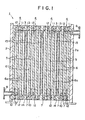
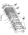
- the drawings show an electrolytic cell 1 which comprises four vertical electrolytic cell units 4, having a pair of endframes 2,2a at the ends with spacers 3 placed between the electrolytic cell units.
- Each electrolytic cell unit 4 comprises a laminar anode 5 interposed between a pair of laminar cathodes 6,6a separated by three gaskets 7.
- the endmost cathodes 6,6a are, respectively, in contact with endframes 2,2a.
- An electrolyte feed passage or inlet 10 penetrates the outermost adjacent cathode at the position corresponding to the electrolyte feed port 8.
- an electrolyte discharge passage or outlet 11 connects the electrolyte discharge port 9 and the outermost adjacent cathode.
- each cathode 2 6,6a has one or two projecting parts 16 on one side, which projecting part 16 is connected by a busbar 17 to a projecting part 18 of the anode 5 of the adjacent electrolytic cell unit 4.
- This apparatus is used as follows in sea water electrolysis.
- the electric current flows from the anode 5 of the electrolytic cell unit 4 positioned at the left hand side of Figure 1 to its cathodes 6,6a on either side.
- the current also flows to the anode of the adjacent electrolytic cell unit through the busbar 17: and thus passes in succession through the electrolytic cell 1 causing the electrolysis of sodium chloride to sodium hypochlorite in the electrolyte.
- sea water is introduced to the electrolytic cell 1 from the feed port 8 on the side of the cell.
- sea water does not contact the bottom edges of the cathodes 6,6a in contrast to conventional electrolytic cells. Therefore, deposits of magnesium and calcium components in sea water are not formed.
- an electrolyte flows from the lower part to the upper part of the electrolytic cell unit 4, the electrolyte is fully electrolyzed in said unit, and the electrolytic efficiency does not decrease.
- An electrolytic cell unit comprised a dimensionally stable anode 50 cm long, 25 cm wide and 3 mm thick, a pair of stainless steel cathodes of the same shape and two picture frame-like 3 mm gaskets placed between the anode and the cathodes.
- An electrolytic cell for sea water as shown in Figure 1 and Figure 2 was formed by utilizing four such electrolytic cell units with spacers, with passages from top to bottom between said units.
- the electrolysis took place at a sea water flow rate through the cell of 900 liters per hour at 300 amperes of electrolytic current.
- the concentration of available chlorine in the electrolyte after electrolysis was about 1600 mg per liter at which current efficiency was 85 to 94%.
- the electrolytic cell was operated for 9 months periods of time.
- the electrolytic cell was disassembled, and deposits such as magnesium hydroxide and calcium hydroxide were not substantially observed on the reactive surfaces.
- An electrolytic cell was assembled with the same elements as in Example 1, but the anodes and cathodes were 100 cm long, 50 cm wide and 3 mm thick and picture frame-like gaskets were 2 mm thick, and the electrolytic cell comprised two electrolytic cell units.
- the electrolysis proceeded at a flow rate of sea water through the cell of 3200 liters per hour, while electric current was fed at 1300 amperes.
- the concentration of available chlorine in the electrolyte after electrolysis was about 1000 mg per liter and the current efficiency was 85 to 95%.
Landscapes
- Chemical & Material Sciences (AREA)
- Organic Chemistry (AREA)
- Engineering & Computer Science (AREA)
- Chemical Kinetics & Catalysis (AREA)
- Electrochemistry (AREA)
- Metallurgy (AREA)
- Materials Engineering (AREA)
- Inorganic Chemistry (AREA)
- General Chemical & Material Sciences (AREA)
- Life Sciences & Earth Sciences (AREA)
- Hydrology & Water Resources (AREA)
- Environmental & Geological Engineering (AREA)
- Water Supply & Treatment (AREA)
- Electrolytic Production Of Non-Metals, Compounds, Apparatuses Therefor (AREA)
Applications Claiming Priority (2)
| Application Number | Priority Date | Filing Date | Title |
|---|---|---|---|
| JP2390/85 | 1985-01-14 | ||
| JP239085 | 1985-01-14 |
Publications (2)
| Publication Number | Publication Date |
|---|---|
| EP0188320A1 true EP0188320A1 (fr) | 1986-07-23 |
| EP0188320B1 EP0188320B1 (fr) | 1990-05-16 |
Family
ID=11527904
Family Applications (1)
| Application Number | Title | Priority Date | Filing Date |
|---|---|---|---|
| EP86300068A Expired - Lifetime EP0188320B1 (fr) | 1985-01-14 | 1986-01-07 | Cellule d'électrolyse pour eau de mer |
Country Status (4)
| Country | Link |
|---|---|
| US (1) | US4654135A (fr) |
| EP (1) | EP0188320B1 (fr) |
| KR (1) | KR930001243Y1 (fr) |
| DE (1) | DE3671252D1 (fr) |
Cited By (1)
| Publication number | Priority date | Publication date | Assignee | Title |
|---|---|---|---|---|
| WO2016105188A1 (fr) * | 2014-12-22 | 2016-06-30 | Exintec Beheer B.V. | Générateur de gaz produit d'électrolyse, système et procédé de génération de gaz produit |
Families Citing this family (8)
| Publication number | Priority date | Publication date | Assignee | Title |
|---|---|---|---|---|
| US5298138A (en) * | 1992-02-28 | 1994-03-29 | Ceramatec, Inc. | Solid electrolyte ion conducting device |
| US5322604A (en) * | 1992-11-02 | 1994-06-21 | Olin Corporation | Electrolytic cell and electrodes therefor |
| KR100374203B1 (ko) * | 2000-11-18 | 2003-03-03 | 주식회사 엠티엘 | 전기 투석장치 |
| JP7593643B2 (ja) * | 2019-01-16 | 2024-12-03 | マサチューセッツ インスティテュート オブ テクノロジー | 酸および塩基を含む反応スキーム、空間的に変化する化学組成勾配を含む反応器、ならびに関連システムおよび方法 |
| BR112021017931A2 (pt) | 2019-03-14 | 2021-11-16 | Massachusetts Inst Technology | Método, e, sistema |
| WO2022204059A1 (fr) | 2021-03-22 | 2022-09-29 | Sublime Systems, Inc. | Mélanges de ciment décarbonés |
| EP4251586A1 (fr) | 2021-12-23 | 2023-10-04 | Graymont Western Canada Inc. | Compositions d'extension de ciment à base de chaux, et systèmes et procédés associés |
| AU2023409369B2 (en) | 2022-12-20 | 2025-08-14 | Graymont Western Canada Inc. | Systems and methods for storing and mineralizing carbon dioxide with lime |
Citations (2)
| Publication number | Priority date | Publication date | Assignee | Title |
|---|---|---|---|---|
| US3119760A (en) * | 1959-12-30 | 1964-01-28 | Standard Oil Co | Electrolytic cell for the oxidation and reduction of organic compounds |
| DE2919527A1 (de) * | 1979-05-11 | 1980-11-20 | Krebskosmo Ges F Chemie Ing Te | Elektrolyseur zur gewinnung von natriumhypochlorit |
Family Cites Families (2)
| Publication number | Priority date | Publication date | Assignee | Title |
|---|---|---|---|---|
| FR2446331A1 (fr) * | 1979-01-10 | 1980-08-08 | Louyot Comptoir Lyon Alemand | Cellule modulaire d'electrolyse pour la recuperation des metaux |
| JPS5924192B2 (ja) * | 1981-05-22 | 1984-06-07 | 日本カ−リツト株式会社 | 塩水電解槽 |
-
1985
- 1985-12-16 US US06/809,300 patent/US4654135A/en not_active Expired - Fee Related
-
1986
- 1986-01-07 DE DE8686300068T patent/DE3671252D1/de not_active Expired - Lifetime
- 1986-01-07 EP EP86300068A patent/EP0188320B1/fr not_active Expired - Lifetime
-
1992
- 1992-11-27 KR KR929223561U patent/KR930001243Y1/ko not_active Expired - Fee Related
Patent Citations (2)
| Publication number | Priority date | Publication date | Assignee | Title |
|---|---|---|---|---|
| US3119760A (en) * | 1959-12-30 | 1964-01-28 | Standard Oil Co | Electrolytic cell for the oxidation and reduction of organic compounds |
| DE2919527A1 (de) * | 1979-05-11 | 1980-11-20 | Krebskosmo Ges F Chemie Ing Te | Elektrolyseur zur gewinnung von natriumhypochlorit |
Non-Patent Citations (1)
| Title |
|---|
| PATENTS ABSTRACTS OF JAPAN, vol. 1, no. 120, 12th October 1977, page 2739 C 77; & JP - A - 52 78 675 (HITACHI DENSEN K.K.) 07-02-1977 * |
Cited By (2)
| Publication number | Priority date | Publication date | Assignee | Title |
|---|---|---|---|---|
| WO2016105188A1 (fr) * | 2014-12-22 | 2016-06-30 | Exintec Beheer B.V. | Générateur de gaz produit d'électrolyse, système et procédé de génération de gaz produit |
| NL2014033B1 (en) * | 2014-12-22 | 2016-10-12 | Exintec Beheer B V | Electrolysis product gas generator, system and method for generating a product gas. |
Also Published As
| Publication number | Publication date |
|---|---|
| US4654135A (en) | 1987-03-31 |
| DE3671252D1 (de) | 1990-06-21 |
| KR930001243Y1 (ko) | 1993-03-22 |
| EP0188320B1 (fr) | 1990-05-16 |
Similar Documents
| Publication | Publication Date | Title |
|---|---|---|
| US4417960A (en) | Novel electrolyzer and process | |
| EP0064417B1 (fr) | Cellule électrochimique et méthode pour effectuer des réactions électrochimiques | |
| US4032426A (en) | Electrolysis cells | |
| US3598715A (en) | Electrolytic cell | |
| AU2016338328B2 (en) | Filter press device for electroplating metal from solutions, which is formed by separating elements formed by ion-exchange membranes, forming a plurality of anolyte and catholyte chambers, the electrodes being connected in series with automatic detachment of the metallic product | |
| JPS5949318B2 (ja) | 次亜ハロゲン酸アルカリ金属塩の電解製造法 | |
| US4584080A (en) | Bipolar electrolysis apparatus with gas diffusion cathode | |
| US3755105A (en) | Vacuum electrical contacts for use in electrolytic cells | |
| US4654135A (en) | Electrolytic cell for sea water | |
| CA1310301C (fr) | Cellule pour extraction electrolytique | |
| EP0013705B1 (fr) | Production électrolytique de chlore et de soude caustique | |
| US4488948A (en) | Channel flow cathode assembly and electrolyzer | |
| US3948750A (en) | Hollow bipolar electrode | |
| US4139449A (en) | Electrolytic cell for producing alkali metal hypochlorites | |
| EP3161185B1 (fr) | Cellule d'électrolyse non divisée à espace étroit | |
| US4059495A (en) | Method of electrolyte feeding and recirculation in an electrolysis cell | |
| US3930980A (en) | Electrolysis cell | |
| CA1073846A (fr) | Methode et appareil d'electrolyse | |
| US4936972A (en) | Membrane electrolyzer | |
| CA1091187A (fr) | Cellule electrolytique | |
| GB1572646A (en) | Preventing or substantially reducing corrosion of cell parts in electrolysis | |
| CA1134779A (fr) | Pile electrolytique | |
| US4269675A (en) | Electrolyte series flow in electrolytic chlor-alkali cells | |
| US4093525A (en) | Method of preventing hydrogen deterioration in a bipolar electrolyzer | |
| US4088551A (en) | Electrolytic cell and method of electrolysis |
Legal Events
| Date | Code | Title | Description |
|---|---|---|---|
| PUAI | Public reference made under article 153(3) epc to a published international application that has entered the european phase |
Free format text: ORIGINAL CODE: 0009012 |
|
| AK | Designated contracting states |
Kind code of ref document: A1 Designated state(s): DE FR GB IT |
|
| 17P | Request for examination filed |
Effective date: 19870123 |
|
| 17Q | First examination report despatched |
Effective date: 19871201 |
|
| GRAA | (expected) grant |
Free format text: ORIGINAL CODE: 0009210 |
|
| AK | Designated contracting states |
Kind code of ref document: B1 Designated state(s): DE FR GB IT |
|
| PG25 | Lapsed in a contracting state [announced via postgrant information from national office to epo] |
Ref country code: FR Effective date: 19900516 |
|
| ITF | It: translation for a ep patent filed | ||
| REF | Corresponds to: |
Ref document number: 3671252 Country of ref document: DE Date of ref document: 19900621 |
|
| EN | Fr: translation not filed | ||
| ITTA | It: last paid annual fee | ||
| PLBE | No opposition filed within time limit |
Free format text: ORIGINAL CODE: 0009261 |
|
| STAA | Information on the status of an ep patent application or granted ep patent |
Free format text: STATUS: NO OPPOSITION FILED WITHIN TIME LIMIT |
|
| 26N | No opposition filed | ||
| PG25 | Lapsed in a contracting state [announced via postgrant information from national office to epo] |
Ref country code: DE Effective date: 19911001 |
|
| PGFP | Annual fee paid to national office [announced via postgrant information from national office to epo] |
Ref country code: GB Payment date: 19921229 Year of fee payment: 8 |
|
| PG25 | Lapsed in a contracting state [announced via postgrant information from national office to epo] |
Ref country code: GB Effective date: 19940107 |
|
| GBPC | Gb: european patent ceased through non-payment of renewal fee |
Effective date: 19940107 |
|
| PG25 | Lapsed in a contracting state [announced via postgrant information from national office to epo] |
Ref country code: IT Free format text: LAPSE BECAUSE OF NON-PAYMENT OF DUE FEES;WARNING: LAPSES OF ITALIAN PATENTS WITH EFFECTIVE DATE BEFORE 2007 MAY HAVE OCCURRED AT ANY TIME BEFORE 2007. THE CORRECT EFFECTIVE DATE MAY BE DIFFERENT FROM THE ONE RECORDED. Effective date: 20050107 |