EP0188321A2 - Drehbar befestigte Reaktorschirmplatte - Google Patents
Drehbar befestigte Reaktorschirmplatte Download PDFInfo
- Publication number
- EP0188321A2 EP0188321A2 EP86300072A EP86300072A EP0188321A2 EP 0188321 A2 EP0188321 A2 EP 0188321A2 EP 86300072 A EP86300072 A EP 86300072A EP 86300072 A EP86300072 A EP 86300072A EP 0188321 A2 EP0188321 A2 EP 0188321A2
- Authority
- EP
- European Patent Office
- Prior art keywords
- shroud
- swingout
- reactor
- affixed
- arms
- Prior art date
- Legal status (The legal status is an assumption and is not a legal conclusion. Google has not performed a legal analysis and makes no representation as to the accuracy of the status listed.)
- Granted
Links
Images


Classifications
-
- G—PHYSICS
- G21—NUCLEAR PHYSICS; NUCLEAR ENGINEERING
- G21C—NUCLEAR REACTORS
- G21C9/00—Emergency protection arrangements structurally associated with the reactor, e.g. safety valves provided with pressure equalisation devices
-
- G—PHYSICS
- G21—NUCLEAR PHYSICS; NUCLEAR ENGINEERING
- G21C—NUCLEAR REACTORS
- G21C11/00—Shielding structurally associated with the reactor
- G21C11/02—Biological shielding ; Neutron or gamma shielding
-
- Y—GENERAL TAGGING OF NEW TECHNOLOGICAL DEVELOPMENTS; GENERAL TAGGING OF CROSS-SECTIONAL TECHNOLOGIES SPANNING OVER SEVERAL SECTIONS OF THE IPC; TECHNICAL SUBJECTS COVERED BY FORMER USPC CROSS-REFERENCE ART COLLECTIONS [XRACs] AND DIGESTS
- Y02—TECHNOLOGIES OR APPLICATIONS FOR MITIGATION OR ADAPTATION AGAINST CLIMATE CHANGE
- Y02E—REDUCTION OF GREENHOUSE GAS [GHG] EMISSIONS, RELATED TO ENERGY GENERATION, TRANSMISSION OR DISTRIBUTION
- Y02E30/00—Energy generation of nuclear origin
- Y02E30/30—Nuclear fission reactors
Definitions
- the present invention is directed to a reactor shroud shield and more particularly to a gamma-ray attenuating shield installed for the protection of technicians working in the region of a reactor head.
- a nuclear reactor typically includes a reactor vessel which is disposed in a concrete well located in the floor of a reactor room.
- a reactor head is bolted to the reactor vessel, which contains water and nuclear fuel housed in an array of fuel assemblies.
- the nuclear fuel heats the water, which is circulated by pipes from the reactor vessel to steam generators and then back to the reactor vessel for reheating.
- control rods of neutron absorbing material are movably mounted within the reactor vessel.
- Control rod drive mechanisms mounted on the reactor head are used to adjust the control rods, with the control rod drive mechanism and various control and sensor devices being housed within a shroud extending upward from the reactor head.
- the nuclear reaction within the vassal is quenched and technicians wearing protective clothing unbolt the reactor head by removing nuts from studs so that the head can be removed from the reactor vessel.
- nuts are large and heavy, and a stud tensioner hoist mounted on a circumferential track is available to assist the technicians in handling the nuts and tools.
- the reactor room is flooded with water to provide shielding and the reactor head, control rod drive mechanisms, shroud, etc., are hoisted by lifting rods attached to the head to expose the depleted fuel assemblies.
- the depleted fuel assemblies are removed, under water, to a pool of borated water for short-term storage.
- the reactor is then refueled and the head assembly, complete with control rod drive mechanisms, etc., is set in place on top the reactor vessel. After the water is drained from the reactor room technicians wearing protective clothing re-enter the reactor room to securely bolt the reactor head to the reactor vessel so that operation can continue.
- the reactor head itself is a hemispherical body typically made of steel, perhaps 18 cm thick, and substantially attenuates gamma-rays from inside the reactor vessel.
- the control rod drive mechanisms during the course of time, tend to accumulate a residue of fission products. Since the control rod drive mechanisms are shielded by the shroud alone, and not by the reactor head, the technicians in the reactor room during the refueling operation are exposed to radiation from the control rod drive mechanisms. While this exposure is a modest one, the steadily increasing safety standards in the nuclear industry have made it desirable to provide additional shielding to the technicians during the refueling operation.
- U.S. Patent 4,432,932 provides additional shielding by suspending quilted blankets of lead wool from short mounting arms fixedly attached to the shroud.
- the technicians install the blankets before undertaking the longer task of bolting or unbolting the reactor head.
- blankets are unwieldy and heavy. Even if the stud tensioner hoist is used to manipulate the blankets as they are being hung or removed, the blankets must still be muscled laterally by the distance between the stud tensioner hoist and the mounting arms on the shroud. This not only increases fatigue, it slows the blanket installation process and consequently increases the exposure to radiation. Moreover, the heavy weight and awkward movements that are necessary increase the possibility of slips or other accidents.
- the primary object of the present invention is to provide a reactor shroud shield which permits shielding members to be installed around the reactor shroud or removed therefrom more expeditiously than in the prior art.
- the present invention resides in an apparatus for shielding persons working around a nuclear reactor having a reactor head and a shroud extending upward from the reactor head, said apparatus being characterized by: a plurality of swingout arms pivotally mounted around said shroud and having free ends movable between first positions spaced apart from the shroud and second positions adjacent the shroud; a plurality of shielding members provided for being supported by said swingout arms and means for hanging said shielding member on said swingout arms.
- Each sliding member has an eye element for engagement by the stud tensioner hoist and hook elements for engagement by the hangers attached to the swingout arms.
- reactor room 20 has concrete walls 22 and floor 24.
- a reactor well 26 extends downward from floor 24.
- Nuclear reactor 28 is housed in room 20 and well 26.
- Reactor 28 includes a generally cylindrical reactor vessel 30 having a mouth portion 32. Nozzles 34 extend from vessel 30 to receive pipes 36, which convey heated water to steam generators (not illustrated) and other apparatus and thence back to reactor 28.
- reactor head 38 is attached to mouth region 32 by studs (not illustrated) around the periphery of mouth region 32 and bolts 40 screwed to the studs.
- a shroud support ring 42 is affixed to head 38 to support shroud 44.
- Three lugs 46 are affixed to head 38 to receive lift rods 48.
- lift rods 48 are used to hoist head 38 and shroud 44.
- Control rod drive mechanisms and other control devices which are not illustrated are housed within shroud 44.
- Shroud 44 may be deemed an "integrated head" shroud, which provides various advantages over older shrouds.
- the present invention is not, however, limited to use with integrated head shrouds. Regardless of the particular design, however, the shroud serves to cool the control rod drive mechanisms therein by circulating air to them.
- shroud 44 includes a lower portion 50, a middle portion 52, and an upper portion 54.
- Portions 50-54 are generally barrel-shaped in configuration, and are jointed one on top of the other to form shroud 44.
- Lower portion 50 includes a ring of vertically positioned metal beams 56 which extend between ring 42 and flange 58.
- Metal doors 58 are positioned between the beams 56.
- One side of each door 58 is mounted by hinges (not illustrated) to a beam 56, and the other side has a handle 60 attached thereto to permit technicians wearing protective clothing to briefly enter shroud 44 in order to service the control rod drive mechanisms, etc.
- Middle portion 52 is constructed much as lower portion 50.
- a ring of vertically disposed metal beams 62 extends between flange 64 and flange 66, which is affixed to flange 58 by a ring of bolts (not illustrated).
- doors are unnecessary between beams 62, so metal panels 68 are permanently affixed between beams 62.
- Flange 69 of upper portion 54 is affixed to flange 64 of middle portion 52 by bolts (Not illustrated).
- an integrated head cooling shroud such as shroud 44, typically has a stud tensioner hoist rail 70 attached thereto by mounting brackets 72, one of which is welded to each beam 62 of middle section 52.
- Rail 70 can be provided by an I-beam which is bent into a circle. Brackets 72 extend radially outward to support beam 70 above the bolts 40.
- Rail 70 provides a track for stud tensioner hoist 74, so that hoist 74 can be moved to a position for use with each bolt 40. Hoist 74 will be described in more detail with reference to Figure 2.
- Stud tensioner hoist 74 includes a housing 76 which encloses such elements (not illustrated) as a motor, reduction gearing, and a pulley. Legs 78 extend upward from housing 76. Wheels 80 are journalled for rotation on legs 78 in order to permit hoist 74 to be rolled along the bottom flange of rail 70. A hook 82 is affixed to bracket 84, which rotatably supports pulley 86. Cable 88 loops around pulley 86 to permit hook 82 to be raised or lowered.
- the present application provides a shielding system which can be applied to reactors which are already in use. In such a case, technicians permanently mount a shield support around the existing shroud, and thereafter shielding can be hung on the support when necessary.
- the workers do not, of course, have the advantage of additional shielding when they are installing the shield support, but this is a one-time task which can be accomplished relatively briefly.
- the radiation exposure when the shield support is mounted is substantially less than the radiation previously received during every refueling.
- the shield support can also be installed when a new reactor is built, so that it need not be retrofit later.
- shield support 90 includes a permanent rail 92 with swingout rails 94 pivotably attached thereto.
- Rail 92 encircles shroud 44, although it may be provided by three 120° sections 96 as illustrated in Figure 3 in order to facilitate installation when the invention is adapted as a retrofit to reactors already in use.
- Section 96 are preferably constructed of bent I-beams.
- Swingout sections 94 are also preferably made of I-beams.
- the pivotable connection between permanent rail 92 and swingout rails 94 may be provided by bolts 98, which extend through bores (for example, see bores 100 in Figure 3) in the I-beams. Nuts 102 are threaded to bolts 98. The pivotable connection permits the rails 94 to be swung outward from fail 92 and then back inward, as illustrated in Figure 5.
- hangers 104 are attached to swingout arms 94, which, in turn, are pivotably mounted to permanent rail 92 as previously described, before shield support 90 is installed if the reactor is already in use.
- Such pre-assembly allows the elements to be installed as a unit, thereby minimizing exposure.
- shield support 90 is affixed to middle portion 52 of shroud 44.
- Mounting brackets 106 are affixed to permanent rail 92 and are positioned to abut beams 62, one bracket l06 for each beam 62.
- Brackets 106 have flanges 108 having bores (not illustrated) through them. During installation the technicians hold support 90 so that a flange 108 lies against a beam 62, and holes are then drilled through the beam 62.
- Bolts 110 are then inserted to secure support 90. This mounting procedure is repeated for the remaining brackets 106.
- each shielding member 112 preferably includes a panel 114 of lead approximately 2 cm thick, which provides a fifty percent reduction in gamma radiation.
- panels 114 may be about 2.8 meters high and about .8 meters wide. Each such panel would have a mass of approximately 160 Kg.
- each panel 114 has a suspension member 116 centered at the top thereof.
- Member 116 includes a mounting bracket 118 which is affixed to panel 114 by bolts 120.
- An eye element 122 and a pair of hook elements 124 are affixed to pin 126, which is rotatably mounted by bracket 118.
- shielding panels 114 The installation of shielding panels 114 will now be described. It will be assumed in the following discussion that support 90 has already been mounted.
- panels 114 are first lowered by a crane (not illustrated) to floor 24 of reactor room 20.
- the hook 82 (see Figure 2) of stud tensioner hoist 74 is then lowered to floor 24 and inserted through the eye 122 (see Figure 2) of a panel 114. Hoist 74 then lifts the panel 114 above floor 24.
- hook elements 124 jut toward hangers 104 when panel 114 is supported by hook 82.
- Panel 114 is lifted, and stud tensioner hoist 74 is pushed along rail 70, until the hooks 114 are aligned with a hanger 104. Thereafter, the swingout rail 94 is pivoted outward, as illustrated in Figure 5, to receive he panel 114.
- Figure 4 illustrates two hangers 104 for every swingout arm 94, in which case two panels 114 are mounted on each swingout arm.
- a single hanger 104 could be used with every swingout arm 94 in order to suspend a single panel 114, or more than two hangers 104 could be used to suspend a corresponding number of panels 114.
- the widths of the panels 114 would differ depending upon how many are used.
- panels 114 are preferred since they can be readily handled, quilted blankets of lead wool might alternately be employed as shielding members 112. Moreover, radiation attenuating materials other than lead can be used.
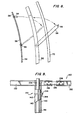
- Figure 8 generally illustrates that permanent rail 92 is mounted between the shroud and stud tensioner hoist rail 70.
- Figure 8 also illustrates that swingout arms 94 can be positioned to allow access to the interior of shroud 44 through doors 58 therein even when the shielding is in place. A technician within the shroud would not, of course, receive the benefit of the shielding.
- FIG 9 illustrates an alternate way to mount the permanent rail of the shield support.
- This alternative mounting technique may be used with integrated head shrouds, such as shroud 44, but it is particularly useful for certain previous shroud designs wherein the shroud itself cannot be used to mount the permanent rail.
- permanent rail 130 is provided by rail segments 132. Three segments 132 are used, each being curved through a circular arc of substantially 120°. Near one end of each segment 132 is a bore 134. The adjacent ends of 'segments 132 are joined by plates 136 and bolts 138. Thus assembled, rail 130 is positioned above the reactor so that bores 134 are aligned with the lift rods 48 (see Figure 1). Rail 130 is then lowered down rods 48.
- Rail 130 is not lowered all the way to reactor head 38. Instead, a pair of sleeves 140 are positioned around the lower portion of each rod 48 and held together by a number of clamps 141.
- Each clamp 141 may include a U-shaped element 142, a bar 144, a nut 146.
- Another alternative for mounting the shield support would be to suspend the permanent rail from the seismic support platform.
- seismic support platforms are used with nuclear reactors to provide lateral support for the control rod drive mechanisms in the event of seismic disturbances.
- the present invention provides a shielding method and system for protecting technicians during refueling of a nuclear reactor.
- Shielding panels are hung in an overlapping manner from a shield support, which can be mounted on the shroud or elsewhere.
- the shield support includes swingout arms which facilitate transfer of the panels from the stud tensioner hoist to their installed positions.
Landscapes
- Engineering & Computer Science (AREA)
- Physics & Mathematics (AREA)
- High Energy & Nuclear Physics (AREA)
- Plasma & Fusion (AREA)
- General Engineering & Computer Science (AREA)
- Biomedical Technology (AREA)
- General Health & Medical Sciences (AREA)
- Molecular Biology (AREA)
- Life Sciences & Earth Sciences (AREA)
- Health & Medical Sciences (AREA)
- Monitoring And Testing Of Nuclear Reactors (AREA)
- Supports For Pipes And Cables (AREA)
- Carriers, Traveling Bodies, And Overhead Traveling Cranes (AREA)
Applications Claiming Priority (2)
| Application Number | Priority Date | Filing Date | Title |
|---|---|---|---|
| US690719 | 1985-01-11 | ||
| US06/690,719 US4654188A (en) | 1985-01-11 | 1985-01-11 | Pivotably mounted reactor shroud shield and shielding method |
Publications (3)
| Publication Number | Publication Date |
|---|---|
| EP0188321A2 true EP0188321A2 (de) | 1986-07-23 |
| EP0188321A3 EP0188321A3 (en) | 1987-10-14 |
| EP0188321B1 EP0188321B1 (de) | 1991-04-10 |
Family
ID=24773661
Family Applications (1)
| Application Number | Title | Priority Date | Filing Date |
|---|---|---|---|
| EP86300072A Expired - Lifetime EP0188321B1 (de) | 1985-01-11 | 1986-01-07 | Drehbar befestigte Reaktorschirmplatte |
Country Status (6)
| Country | Link |
|---|---|
| US (1) | US4654188A (de) |
| EP (1) | EP0188321B1 (de) |
| JP (1) | JPS61164188A (de) |
| KR (1) | KR940002807B1 (de) |
| CN (1) | CN1004180B (de) |
| ES (1) | ES8707372A1 (de) |
Cited By (4)
| Publication number | Priority date | Publication date | Assignee | Title |
|---|---|---|---|---|
| WO1990010295A1 (en) * | 1989-02-27 | 1990-09-07 | Combustion Engineering, Inc. | Reactor head shielding apparatus |
| EP0389186A3 (en) * | 1989-03-20 | 1990-12-12 | Westinghouse Electric Corporation | Cover for protecting an operator from radiation emission |
| FR2674669A1 (fr) * | 1991-03-28 | 1992-10-02 | Sociel Sa | Protection biologique. |
| DE102010052320B3 (de) * | 2010-11-25 | 2012-03-01 | Areva Np Gmbh | Abschirmring für einen Kernreaktor |
Families Citing this family (18)
| Publication number | Priority date | Publication date | Assignee | Title |
|---|---|---|---|---|
| US4828789A (en) * | 1984-02-03 | 1989-05-09 | Westinghouse Electric Corp. | Reactor vessel head permanent shield |
| US5037604A (en) | 1989-06-19 | 1991-08-06 | Westinghouse Electric Corp. | Coffer dam for temporary shielding of reactor vessel internals |
| US5009836A (en) * | 1989-06-19 | 1991-04-23 | Westinghouse Electric Corp. | Method for temporary shielding of reactor vessel internals |
| US5488643A (en) * | 1994-05-11 | 1996-01-30 | Combustion Engineering, Inc. | Method and apparatus for supporting a shroud in a nuclear reactor |
| US5664502A (en) * | 1994-07-27 | 1997-09-09 | Westinghouse Electric Corporation | Wheel assembly capable of maintaining engagement with a rail having an uneven portion therein |
| US5715288A (en) * | 1996-05-09 | 1998-02-03 | Combustion Engineering, Inc. | Integral head rig, head area cable tray and missile shield for pressurized water reactor |
| US5774513A (en) * | 1997-01-14 | 1998-06-30 | Combustion Engineering, Inc. | Head area cable tray bridge |
| US6639960B2 (en) * | 2000-10-06 | 2003-10-28 | Westinghouse Electric Company Llc | Method of retrofitting a reactor pressure vessel head assembly |
| US20040101084A1 (en) * | 2001-08-02 | 2004-05-27 | Advent Engineering Services, Inc. | Integrated head assembly for a nuclear reactor |
| US6546066B2 (en) * | 2001-08-02 | 2003-04-08 | Advent Engineering Services, Inc. | Integrated head assembly for a nuclear reactor |
| US7567645B2 (en) * | 2005-07-19 | 2009-07-28 | Advent Engineering Services, Inc. | Modular integrated head assembly |
| US7608847B2 (en) * | 2005-12-16 | 2009-10-27 | Rees Chet R | System and method for implementing a suspended personal radiation protection system |
| US7973299B2 (en) * | 2008-01-18 | 2011-07-05 | Rees Chet R | System and method for providing a suspended personal radiation protection system |
| US8598554B2 (en) | 2008-01-18 | 2013-12-03 | Interventco, Llc | System and method for providing a suspended personal radiation protection system |
| US20090256044A1 (en) * | 2008-04-14 | 2009-10-15 | Steve Miller | Suspension system and method |
| US8532245B2 (en) * | 2008-12-17 | 2013-09-10 | Westinghouse Electric Company Llc | Core shroud corner joints |
| KR101653942B1 (ko) * | 2016-02-23 | 2016-09-02 | 문인득 | 원자로 증기 발생기의 하부 구조물 냉각장치 |
| CN110329966A (zh) * | 2019-06-18 | 2019-10-15 | 沪东中华造船(集团)有限公司 | 克令吊螺栓拉伸器抬升装置 |
Family Cites Families (18)
| Publication number | Priority date | Publication date | Assignee | Title |
|---|---|---|---|---|
| DE1466848A1 (de) * | 1964-03-14 | 1969-02-20 | Koch & Sterzel Kg | Sekundaerstrahlenschutzvorrichtung an Roentgenuntersuchungsgeraeten |
| US3286094A (en) * | 1964-03-24 | 1966-11-15 | John I Pretto | Radiation energy shield protecting a body area of a patient from x-rays and the like |
| FR1396127A (fr) * | 1964-05-23 | 1965-04-16 | Chirana Praha Np | Paroi de radioscopie orientable |
| FR1441764A (fr) * | 1965-04-30 | 1966-06-10 | Calhene | Paroi de protection |
| DE1789001A1 (de) * | 1968-09-19 | 1972-01-20 | Siemens Ag | Schutzeinrichtung |
| US3680498A (en) * | 1968-12-04 | 1972-08-01 | Charles J Roos | Structure and a method for isolating a building against radioactive fallout |
| US3766006A (en) * | 1970-07-08 | 1973-10-16 | Westinghouse Electric Corp | Rapidly refuelable nuclear reactor |
| US3785925A (en) * | 1971-09-01 | 1974-01-15 | Transfer Systems | Portable radiation shield for nuclear reactor installation |
| DE2360016C3 (de) * | 1973-12-01 | 1982-04-22 | L. & C. Steinmüller GmbH, 5270 Gummersbach | Verfahren zum Abschirmen radioaktiver Strahlungsbereiche |
| US4062518A (en) * | 1976-11-10 | 1977-12-13 | General Electric Company | X-ray shielding device |
| US4123662A (en) * | 1977-03-07 | 1978-10-31 | The B.F. Goodrich Company | Shield bag |
| US4200172A (en) * | 1978-04-14 | 1980-04-29 | Westinghouse Electric Corp. | Radiation shielded movable work station apparatus |
| DE2838519A1 (de) * | 1978-09-04 | 1980-03-20 | Marianne Dr Med Herr | Strahlenschutzvorrichtung, insbesondere fuer roentgenologie, strahlentherapie und diagnostik |
| FR2475781A1 (fr) * | 1980-02-08 | 1981-08-14 | Framatome Sa | Ensemble de commande d'un reacteur nucleaire |
| US4360736A (en) * | 1980-04-15 | 1982-11-23 | Weissenfluh John A | Radiation shield |
| US4432932A (en) * | 1980-11-10 | 1984-02-21 | Earl B. Jacobson | Reactor head shielding system |
| US4530813A (en) * | 1980-11-10 | 1985-07-23 | Jacobson Earl Bruce | Modular reactor head shielding system |
| DE3326880A1 (de) * | 1983-07-26 | 1985-02-07 | Knut Dr. 7802 Merzhausen Korth | Schutzvorrichtung |
-
1985
- 1985-01-11 US US06/690,719 patent/US4654188A/en not_active Expired - Fee Related
-
1986
- 1986-01-07 EP EP86300072A patent/EP0188321B1/de not_active Expired - Lifetime
- 1986-01-07 ES ES550695A patent/ES8707372A1/es not_active Expired
- 1986-01-10 KR KR1019860000108A patent/KR940002807B1/ko not_active Expired - Lifetime
- 1986-01-10 CN CN86100114.1A patent/CN1004180B/zh not_active Expired
- 1986-01-10 JP JP61002303A patent/JPS61164188A/ja active Pending
Cited By (5)
| Publication number | Priority date | Publication date | Assignee | Title |
|---|---|---|---|---|
| WO1990010295A1 (en) * | 1989-02-27 | 1990-09-07 | Combustion Engineering, Inc. | Reactor head shielding apparatus |
| US5084233A (en) * | 1989-02-27 | 1992-01-28 | Combustion Engineering, Inc. | Reactor head shielding apparatus |
| EP0389186A3 (en) * | 1989-03-20 | 1990-12-12 | Westinghouse Electric Corporation | Cover for protecting an operator from radiation emission |
| FR2674669A1 (fr) * | 1991-03-28 | 1992-10-02 | Sociel Sa | Protection biologique. |
| DE102010052320B3 (de) * | 2010-11-25 | 2012-03-01 | Areva Np Gmbh | Abschirmring für einen Kernreaktor |
Also Published As
| Publication number | Publication date |
|---|---|
| CN86100114A (zh) | 1986-09-03 |
| KR940002807B1 (ko) | 1994-04-02 |
| KR860006112A (ko) | 1986-08-18 |
| ES8707372A1 (es) | 1987-07-16 |
| EP0188321A3 (en) | 1987-10-14 |
| US4654188A (en) | 1987-03-31 |
| EP0188321B1 (de) | 1991-04-10 |
| CN1004180B (zh) | 1989-05-10 |
| JPS61164188A (ja) | 1986-07-24 |
| ES550695A0 (es) | 1987-07-16 |
Similar Documents
| Publication | Publication Date | Title |
|---|---|---|
| EP0188321B1 (de) | Drehbar befestigte Reaktorschirmplatte | |
| US5225150A (en) | Integrated head package for top mounted nuclear instrumentation | |
| JP4850214B2 (ja) | 炉内構造物の搬出方法 | |
| WO2016148832A9 (en) | Reactor module support structure | |
| US4530813A (en) | Modular reactor head shielding system | |
| US20040101084A1 (en) | Integrated head assembly for a nuclear reactor | |
| US4828789A (en) | Reactor vessel head permanent shield | |
| EP0004861B1 (de) | Bewegbare strahlungsgeschützte Arbeitsstation | |
| EP0077573B1 (de) | Schieneneinrichtung um einen Kernreaktordruckbehälter herum, sowie Verfahren zu ihrer Installation | |
| US5084233A (en) | Reactor head shielding apparatus | |
| JP2002131483A (ja) | 大型構造物の取扱方法 | |
| JP4055157B2 (ja) | 原子炉圧力容器交換方法 | |
| JPWO2002011151A1 (ja) | 原子炉炉内構造物の保全方法 | |
| JP2000304890A (ja) | 炉内構造物取替方法 | |
| JPH0810266B2 (ja) | ガイドロッド | |
| JP3340398B2 (ja) | 原子炉圧力容器の取り扱い方法 | |
| JPH02129595A (ja) | ラックの床固定装置 | |
| JP2000249791A (ja) | 炉心シュラウドの交換方法 | |
| JP2025154828A (ja) | 原子炉建屋の構築方法および屋根構造体 | |
| JPH0159555B2 (de) | ||
| JP4096911B2 (ja) | 原子炉圧力容器交換方法 | |
| JPH08194085A (ja) | 原子炉のシュラウドの吊り込み方法およびシュラウド構造 | |
| JP2783606B2 (ja) | インコアストロングバック | |
| JPH0540193A (ja) | 原子炉内蔵型ポンプ用部品着脱装置 | |
| CN111847235A (zh) | 一种钢结构防晃安全型吊装装置 |
Legal Events
| Date | Code | Title | Description |
|---|---|---|---|
| PUAI | Public reference made under article 153(3) epc to a published international application that has entered the european phase |
Free format text: ORIGINAL CODE: 0009012 |
|
| AK | Designated contracting states |
Kind code of ref document: A2 Designated state(s): BE FR GB IT SE |
|
| PUAL | Search report despatched |
Free format text: ORIGINAL CODE: 0009013 |
|
| AK | Designated contracting states |
Kind code of ref document: A3 Designated state(s): BE FR GB IT SE |
|
| 17P | Request for examination filed |
Effective date: 19880411 |
|
| 17Q | First examination report despatched |
Effective date: 19890912 |
|
| ITF | It: translation for a ep patent filed | ||
| GRAA | (expected) grant |
Free format text: ORIGINAL CODE: 0009210 |
|
| PGFP | Annual fee paid to national office [announced via postgrant information from national office to epo] |
Ref country code: FR Payment date: 19910328 Year of fee payment: 7 |
|
| AK | Designated contracting states |
Kind code of ref document: B1 Designated state(s): BE FR GB IT SE |
|
| PG25 | Lapsed in a contracting state [announced via postgrant information from national office to epo] |
Ref country code: SE Effective date: 19910410 |
|
| ET | Fr: translation filed | ||
| PGFP | Annual fee paid to national office [announced via postgrant information from national office to epo] |
Ref country code: BE Payment date: 19911213 Year of fee payment: 7 |
|
| PG25 | Lapsed in a contracting state [announced via postgrant information from national office to epo] |
Ref country code: GB Effective date: 19920107 |
|
| PLBE | No opposition filed within time limit |
Free format text: ORIGINAL CODE: 0009261 |
|
| STAA | Information on the status of an ep patent application or granted ep patent |
Free format text: STATUS: NO OPPOSITION FILED WITHIN TIME LIMIT |
|
| 26N | No opposition filed | ||
| GBPC | Gb: european patent ceased through non-payment of renewal fee | ||
| PG25 | Lapsed in a contracting state [announced via postgrant information from national office to epo] |
Ref country code: BE Effective date: 19930131 |
|
| BERE | Be: lapsed |
Owner name: WESTINGHOUSE ELECTRIC CORP. Effective date: 19930131 |
|
| PG25 | Lapsed in a contracting state [announced via postgrant information from national office to epo] |
Ref country code: FR Effective date: 19930930 |
|
| REG | Reference to a national code |
Ref country code: FR Ref legal event code: ST |
|
| PG25 | Lapsed in a contracting state [announced via postgrant information from national office to epo] |
Ref country code: IT Free format text: LAPSE BECAUSE OF NON-PAYMENT OF DUE FEES;WARNING: LAPSES OF ITALIAN PATENTS WITH EFFECTIVE DATE BEFORE 2007 MAY HAVE OCCURRED AT ANY TIME BEFORE 2007. THE CORRECT EFFECTIVE DATE MAY BE DIFFERENT FROM THE ONE RECORDED. Effective date: 20050107 |