EP0188657B1 - Système de régulation pour moteur linéaire de propulsion d'un support subdivisé - Google Patents
Système de régulation pour moteur linéaire de propulsion d'un support subdivisé Download PDFInfo
- Publication number
- EP0188657B1 EP0188657B1 EP85110711A EP85110711A EP0188657B1 EP 0188657 B1 EP0188657 B1 EP 0188657B1 EP 85110711 A EP85110711 A EP 85110711A EP 85110711 A EP85110711 A EP 85110711A EP 0188657 B1 EP0188657 B1 EP 0188657B1
- Authority
- EP
- European Patent Office
- Prior art keywords
- carrier
- linear induction
- track
- transportation system
- carriers
- Prior art date
- Legal status (The legal status is an assumption and is not a legal conclusion. Google has not performed a legal analysis and makes no representation as to the accuracy of the status listed.)
- Expired - Lifetime
Links
- 230000006698 induction Effects 0.000 claims description 48
- 238000006243 chemical reaction Methods 0.000 claims description 22
- 239000000969 carrier Substances 0.000 claims description 17
- 230000001133 acceleration Effects 0.000 claims description 16
- 230000001105 regulatory effect Effects 0.000 claims description 7
- 238000010304 firing Methods 0.000 claims description 6
- 230000006870 function Effects 0.000 claims description 5
- 238000012544 monitoring process Methods 0.000 claims description 5
- 230000001276 controlling effect Effects 0.000 claims description 4
- 230000003287 optical effect Effects 0.000 claims description 4
- 230000005672 electromagnetic field Effects 0.000 claims description 3
- 230000003993 interaction Effects 0.000 claims description 3
- 230000004044 response Effects 0.000 claims description 2
- 230000005540 biological transmission Effects 0.000 claims 1
- 230000008859 change Effects 0.000 description 3
- 230000003247 decreasing effect Effects 0.000 description 3
- 238000010586 diagram Methods 0.000 description 3
- 238000004804 winding Methods 0.000 description 3
- 239000002184 metal Substances 0.000 description 2
- 229910052751 metal Inorganic materials 0.000 description 2
- 230000001360 synchronised effect Effects 0.000 description 2
- 229910001369 Brass Inorganic materials 0.000 description 1
- RYGMFSIKBFXOCR-UHFFFAOYSA-N Copper Chemical compound [Cu] RYGMFSIKBFXOCR-UHFFFAOYSA-N 0.000 description 1
- 229910000831 Steel Inorganic materials 0.000 description 1
- 239000004411 aluminium Substances 0.000 description 1
- 229910052782 aluminium Inorganic materials 0.000 description 1
- XAGFODPZIPBFFR-UHFFFAOYSA-N aluminium Chemical compound [Al] XAGFODPZIPBFFR-UHFFFAOYSA-N 0.000 description 1
- 239000010951 brass Substances 0.000 description 1
- 239000010949 copper Substances 0.000 description 1
- 229910052802 copper Inorganic materials 0.000 description 1
- 230000000694 effects Effects 0.000 description 1
- 230000008030 elimination Effects 0.000 description 1
- 238000003379 elimination reaction Methods 0.000 description 1
- 239000000463 material Substances 0.000 description 1
- 150000002739 metals Chemical class 0.000 description 1
- 230000004048 modification Effects 0.000 description 1
- 238000012986 modification Methods 0.000 description 1
- 238000011084 recovery Methods 0.000 description 1
- 230000009467 reduction Effects 0.000 description 1
- 239000010959 steel Substances 0.000 description 1
- 238000010408 sweeping Methods 0.000 description 1
Images

Classifications
-
- B—PERFORMING OPERATIONS; TRANSPORTING
- B60—VEHICLES IN GENERAL
- B60L—PROPULSION OF ELECTRICALLY-PROPELLED VEHICLES; SUPPLYING ELECTRIC POWER FOR AUXILIARY EQUIPMENT OF ELECTRICALLY-PROPELLED VEHICLES; ELECTRODYNAMIC BRAKE SYSTEMS FOR VEHICLES IN GENERAL; MAGNETIC SUSPENSION OR LEVITATION FOR VEHICLES; MONITORING OPERATING VARIABLES OF ELECTRICALLY-PROPELLED VEHICLES; ELECTRIC SAFETY DEVICES FOR ELECTRICALLY-PROPELLED VEHICLES
- B60L15/00—Methods, circuits, or devices for controlling the traction-motor speed of electrically-propelled vehicles
- B60L15/002—Methods, circuits, or devices for controlling the traction-motor speed of electrically-propelled vehicles for control of propulsion for monorail vehicles, suspension vehicles or rack railways; for control of magnetic suspension or levitation for vehicles for propulsion purposes
- B60L15/005—Methods, circuits, or devices for controlling the traction-motor speed of electrically-propelled vehicles for control of propulsion for monorail vehicles, suspension vehicles or rack railways; for control of magnetic suspension or levitation for vehicles for propulsion purposes for control of propulsion for vehicles propelled by linear motors
-
- B—PERFORMING OPERATIONS; TRANSPORTING
- B60—VEHICLES IN GENERAL
- B60L—PROPULSION OF ELECTRICALLY-PROPELLED VEHICLES; SUPPLYING ELECTRIC POWER FOR AUXILIARY EQUIPMENT OF ELECTRICALLY-PROPELLED VEHICLES; ELECTRODYNAMIC BRAKE SYSTEMS FOR VEHICLES IN GENERAL; MAGNETIC SUSPENSION OR LEVITATION FOR VEHICLES; MONITORING OPERATING VARIABLES OF ELECTRICALLY-PROPELLED VEHICLES; ELECTRIC SAFETY DEVICES FOR ELECTRICALLY-PROPELLED VEHICLES
- B60L2200/00—Type of vehicles
- B60L2200/26—Rail vehicles
-
- B—PERFORMING OPERATIONS; TRANSPORTING
- B60—VEHICLES IN GENERAL
- B60L—PROPULSION OF ELECTRICALLY-PROPELLED VEHICLES; SUPPLYING ELECTRIC POWER FOR AUXILIARY EQUIPMENT OF ELECTRICALLY-PROPELLED VEHICLES; ELECTRODYNAMIC BRAKE SYSTEMS FOR VEHICLES IN GENERAL; MAGNETIC SUSPENSION OR LEVITATION FOR VEHICLES; MONITORING OPERATING VARIABLES OF ELECTRICALLY-PROPELLED VEHICLES; ELECTRIC SAFETY DEVICES FOR ELECTRICALLY-PROPELLED VEHICLES
- B60L2220/00—Electrical machine types; Structures or applications thereof
- B60L2220/10—Electrical machine types
- B60L2220/12—Induction machines
-
- Y—GENERAL TAGGING OF NEW TECHNOLOGICAL DEVELOPMENTS; GENERAL TAGGING OF CROSS-SECTIONAL TECHNOLOGIES SPANNING OVER SEVERAL SECTIONS OF THE IPC; TECHNICAL SUBJECTS COVERED BY FORMER USPC CROSS-REFERENCE ART COLLECTIONS [XRACs] AND DIGESTS
- Y02—TECHNOLOGIES OR APPLICATIONS FOR MITIGATION OR ADAPTATION AGAINST CLIMATE CHANGE
- Y02T—CLIMATE CHANGE MITIGATION TECHNOLOGIES RELATED TO TRANSPORTATION
- Y02T10/00—Road transport of goods or passengers
- Y02T10/60—Other road transportation technologies with climate change mitigation effect
- Y02T10/64—Electric machine technologies in electromobility
Definitions
- This invention relates to a tracked multiple carrier transportation system.
- the system employs a series of linear induction motors spaced along a track.
- a plurality of carriers are used for moving objects through the system.
- a reaction plate is mounted on each carrier and acts as a secondary for the linear induction motors.
- the secondary is designed to interact with the two stator halves of the motor. The interaction between the reaction plate and the electromagnetic field generated by the linear induction motors produces a mechanical thrust which propels the carriers down the track.
- a tracked vehicle propulsion system employs a plurality of linear synchronous motors. Trains of cars are mounted to ride along a track. Each car bears a linear rotor having interdigitated magnetic poles and is propelled by successive linear motors. Every motor, or thruster, is provided with thruster control that is connected to establish inter-thruster logic.
- the velocity of the cars in the Starkey patent is controlled by regulating the input frequency to the linear synchronous motors. Change in speed is achieved by sweeping the stator frequency from synchronism with one frequency to synchronism with another frequency.
- the input frequency does not act as a control signal.
- a change in carrier velocity is achieved by regulating the input voltage to linear induction motors. The thrust produced is proportional to the square of the input voltage.
- the subject invention uses a reaction plate which is a flat piece of metal which interacts with the stators of the linear induction motors.
- the reaction plate is positioned to pass over the stators.
- the reaction plate can be made of a variety of metals, including brass, steel, copper and aluminium, or a combination of these materials.
- the electromagnetic forces induced from the stators (primary) to the reaction plate (secondary) produces energy in the form of electromagnetic thrust.
- the Starkey patent discloses a similar thrust. However, that system utilizes a secondary consisting of interdigitated magnetic poles. This is clearly different than the present system and serves to highlight the differences between the two types of motors used.
- the speed and acceleration of the train in the Nakamura patent does not play a part in the control logic.
- the linear thrusters are energized and de-energized depending solely on the presence or absence of the train.
- An object of the present invention is to provide a transportation system for automated carrier movements, which may be advantageously employed in an assembly line environment.
- the object stated is solved by the features of claim 1.
- a control system utilizing a series of feedback loops and a central computer is employed to monitor and coordinate the movements of the carriers in the system.
- Each loop consists of a linear induction motor, a position sensor, a position indicator and a control module.
- the feedback loops are interconnected via the control modules which, in turn, are connected to the central computer.
- a position indicator which is attached to the carrier is read by a position sensor which is located near the linear induction motor.
- the sensor relays position information to the control module.
- the control module electronically determines the velocity and acceleration of the carrier. These values are then compared to a set of velocity and acceleration curves stored in the module memory. Using the difference between the calculated and stored information, control signals are generated for increasing, decreasing or maintaining the strength of power input to the linear induction motor.
- Means for monitoring the power input to the motor, for reversing the sense of the power flow, and for disconnecting the power supply are all included in the control module. Accordingly, the position, velocity and acceleration of the carrier units are controlled by regulating the magnitude and sense of the power input to the various linear induction motors.
- the thrust produced by a linear induction motor is proportional to the square of its input voltage. By increasing the power input, a greater thrust is produced. The force associated with this thrust translates into a proportional acceleration for the carrier. Deceleration of a carrier is achieved by reversing the direction of the input flow. This generates a thrust in a direction opposite to the movement of the carrier, thereby reducing the speed of the carrier. Once a desired velocity is achieved, the input to the induction motor, or motors, is held at a constant level.
- each control module contains means for disconnecting the power input supply should dangerously high currents in the motor develop or should the position sensor detect the absence of a carrier unit.
- the linear induction motors are positioned along the track to provide continuous electromagnetic contact with the carrier reaction plates. As a reaction plate leaves the influence of one induction motor, it is simultaneously entering the field generated by a subsequent motor.
- the present invention teaches an arrangement in which virtually all of the elements can be arranged below ground level.
- position sensors and indicators may be employed in this type of system. For instance, an induction transducer and a series of equally spaced magnetic strips may be used. Similarly, an optical sensor and bar code could also be used. In fact, any suitable system capable of transmitting and receiving position information can be employed. The system, however, must be capable of sensing the presence or absence of the carriers, identifying each unit, and transmitting and receiving information capable of being transformed into velocity and acceleration data.
- the computer functions to monitor and regulate the operation of the entire system. It should be capable of keeping track of each unit in the system. The desired position, velocity and acceleration of each unit, at each point in the system should also be programmed into the central computer.
- the computer acts to alert the individual control modules to this information, and directs them to generate control signals for keeping the system running smoothly.
- the information received by the computer from the various control modules may be relayed to subsequent control modules, thus coordinating the various feedback loops.
- control module could be incorporated into the central computer.
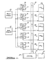
- Fig. 1 is a simplified block diagram of the basic operating units in the system. Represented is a portion of a track 20 on which a plurality of carriers 23 ride. Shown is a central data computer 21 and a power supply source 22. Along the track are situated components which together comprise a series of feedback loops. Each loop consists of a linear induction motor 24, a position indicator 25, a position sensor 26 and a control module 19 to power and regulate the carriers as they move through the system. The loops are interconnected via the control modules 19 which, in turn, are connected to the central data computer 21. This allows the computer to monitor and coordinate the control signal generated in each feedback loop.
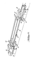
- a reaction plate 27 which is affixed to the carrier 23, passes over the stators 28 of the linear induction motors 24.
- the interaction between the plate 27 and the electromagnetic field generated within the motors 24 results in a thrust which propels the carrier 23 along the track 20.
- the motors 24 are positioned to provide continuous electromagnetic contact with the reaction plate 27. As the carrier leaves the influence of one linear motor 24, it is simultaneously entering the influence of a subsequent motor.
- a position indicator 25 is affixed to each carrier 23 such that it is able to communicate position information to the position sensors 26 located near each linear induction motor 24. Information from the sensor 26 is relayed to the Data Computer 21 via the control module 19.
- the control module 19 electronically determines the velocity and acceleration of the carrier units 23 and compares these values to a set of predetermined data values stored in the memory of the module 19. Deviations between the calculated values and the reference values result in a control signal being generated to regulate the power input from the power source 22 into the linear induction motor.
- a plurality of feedback loops are located along the track 20. This allows the speed of the carriers 23 to be regulated at each point in the system.
- a carrier unit 23 has entered the sphere, or range of influence of a linear induction motor 24 and position sensor 26.
- the indicator 25 attached to the carrier 23 is in position to be read by the sensor 26.
- the indicator 25 is considered an integral part of each loop because even in its absence, it affects the control signals generated. Where the sensor 26 does not detect the presence of an indicator 25, the power supply is electronically disconnected from the linear induction motor 24.
- the position sensor 26 is an induction transducer. It is located off to the side of the track 20 and is positioned to read the position indicator 25 attached to the carrier 23.
- the position indicator 25 in this particular embodiment is a series of equally spaced conductive strips or markings 31 attached to the side of the carrier 23. As the carrier 23 moves past the position sensor 26, the conductive strips or markings 31 will interfere with the magnetic field of position sensor 26 allowing it to generate pulses indicative of the carrier's position.
- Immediately available from the position pulse via computation is the velocity and acceleration values of the carrier. These values are the first and second derivatives of the position pulse, and are calculated by the control module 19. Based on these calculations, the control module 19 generates control signals for regulating the power input to the linear induction motor.
- Position sensors 26 and indicators 25 could take other forms. For instance, an optical sensor and bar code combination could be employed. The type of sensor and indicator selected is essentially a design choice.
- the control module 19 which is responsible for generating control signals is comprised of various component parts. Fig. 3 illustrates these various parts. Within each module is a microprocessor 32, a reversing relay 33, a firing module 34, a reversing contact 35, a switching device 36 and a power supply contactor 37 which deliver power to the linear induction motor (LIM) 24 in short bursts, so as not to burn out the stator windings contained therein.
- LIM linear induction motor
- the data computer 21 is connected to each control module 19 via the microprocessors 32.
- the computer 21 functions to monitor and control the movement of each carrier in the system. It achieves this by coordinating the signals generated in each control module.
- the computer 21 should possess the capability of compensating for gaps in the system if certain stations or areas along the track 20 are down. In addition, it should contain the basic velocity requirements for each station, the basic acceleration or deceleration requirements and the desired positions of each carrier 23 at each point along the track.
- a station offset constant should also be stored in the computer 21 memory. All data can be down loaded and, if necessary, updated at a later date.
- the use of a central data computer 21 makes error recovery quicker and easier, and eliminates the need to independently program each microprocessor 32.
- the microprocessor 32 serves to receive store, and act upon information received from the central computer 21. In addition, it is responsible for receiving input from the position sensor 26 and for generating control signals to operate the other components within the control module.
- the microprocessor 32 is the component in the control module which determines the velocity and acceleration of the carrier as it passes the position sensor. To determine this, the microprocessor utilizes the information from the sensor to compute the first and second derivative of the position pulse. These values are compared to a set of predetermined values stored in the microprocessor memory. Using the difference between the calculated and stored values, the microprocessor 32 generates control signals for increasing, decreasing or maintaining the power input supply to the linear induction motor 24.
- microprocessor 32 and the function of the data computer 21 could be incorporated into a central control computer. This is a design choice.
- the magnitude of the input supply determines whether an increase or decrease in carrier's 23 speed will be affected.
- the thrust on the carrier reactor plate 27 increases and produces an acceleration in the carrier's 23 velocity.
- a speed reduction is achieved.
- a thrust in the direction opposing the carrier's movement is produced, thus creating a rapid braking effect.
- the velocity and acceleration of the carrier 23 is regulated by controlling the magnitude and sense of the power input to the linear induction motors 24.
- the firing module 34 receives control signals from the microprocessor 32 and acts to energize the linear induction motor 24.
- the firing module 34 is connected to the central power source 22. It controls the voltage supplied to the motor 24. If there is no input from the microprocessor 32, the power supply contactors 37 are removed and the power disengaged.
- the reversing relays 33 and contactors 35 operate should deceleration of a carrier 23 become necessary. These components are controlled by the microprocessor 32. They operate to reverse the sense of the power into the linear induction motor 24.
- the switching device 36 is sized to the linear induction motor 24. It delivers power to the motor 24 in short bursts. This helps to prevent excessively high currents from developing in the motor 24, which would burn out the motor's stator windings.
- the microprocessor 32 generates signals to operate the reversing relay 33, the firing module 34 and the reversing contactor 35 in response to the information it receives from the position sensor 26 and the appropriate control algorithm in the data computer 21. These signals act to control the magnitude and the sense of the power input to the linear induction motor 24.
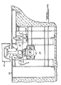
- Fig. 4 provides a cross-sectional view of the disclosed invention, as applied to an assembly line environment.
- the carrier 23 is situated above ground level 38. It carries a workpiece 40. Rigidly mounted to the bottom of the carrier is a guide pole 41.
- the guide pole 41 extends into the track 20 and beneath the ground level 38.
- the guide pole 41 is bolted by a series of bolts 42 to a bracket 43 on which the position indicator 25 is located.
- a reaction plate 27 is attached to the bracket 43.
- the reaction plate 27 is situated to pass over stators 28 of the linear induction motor 24, which is located off to the side of the carrier unit 23.
- a guide rail 44 is provided directly above the linear induction motor 24 and the upwardly extending arm 45 of the carrier reaction plate 27 is restricted by the guide rail 44.
- the rail 44 and arm 45 serve to maintain a suitable gap between the sides of the linear induction motor 24 and the reaction plate 27.
- Affixed to the bottom of the bracket 43 is a pivoting apparatus 46 and bearing support 49.
- the apparatus 46 is provided with a plurality of rollers 47 which ride in a rail track 48 as indicated.
- the position sensor 26 is located across from the linear induction motor 24.
- the position indicator 25 passes in front of the sensor 26 as the carrier 23 moves down the track 20.
- a plurality of linear induction motors 24 would be located along the track 20.
- the desired speed of the carriers at different work stations on the line would be programmed into the computer 21.
- the computer 21, in conjunction with the feedback loops associated with each motor 24, would make it possible to vary the speed and position of the carrier 23 as required.
- the disclosed system offers several advantages over current assembly line systems. These include the elimination of mechanical linkages and power transmitting apparatuses.
Landscapes
- Engineering & Computer Science (AREA)
- Power Engineering (AREA)
- Transportation (AREA)
- Mechanical Engineering (AREA)
- Control Of Vehicles With Linear Motors And Vehicles That Are Magnetically Levitated (AREA)
- Control Of Linear Motors (AREA)
Claims (12)
- Système de transport à supports multiples, utilisable dans des unités déplaçables le long d'une course prédéterminée, du type comprenant :
un rail (20) qui délimite la course;
une pluralité de supports (23) aptes à rouler sur le rail;
une série de moteurs à induction linéaires (24) positionnés le long du rail (20) qui fonctionnent de manière à générer une poussée suffisante pour propulser les supports dans le système, la poussée étant produite par l'interaction entre des moyens de réaction attachés à chacun dès supports et le champ électromagnétique généré par les moteurs;
au moins une source d'alimentation en courant (22) pour activer les moteurs à induction linéaires (24)
caractérisé par
un plateau de réaction (27) allongé et attaché à chacun des supports (23),
des moyens de vérification de position (25, 26) pour identifier et situer la position des supports (23) alors qu'ils se déplacent le long du rail (20), un module de commande (21, 32, 33 , 34, 35, 36) pour commander le mouvement du support (23) en réponse à un signal de retour provenant des moyens de vérification de position (25, 26), des moyens formant processeur (32) qui sont associés au module de commande pour déterminer la vitesse et l' accélération des supports, pour comparer ces valeurs de vitesse et d'accélération à un jeu de courbes de vitesse et d'accélération emmagasinées dans la mémoire du moyen formant processeur (32), et pour générer un signal de commande de manière à contrôler la tension fournie au moteur à induction linéaire (24) par la source d'alimentation en courant (22), ledit module de commande comprenant des moyens de démarrage (24) pour réguler l'amplitude du courant électrique fourni au moteur à induction linéaire (24) et des moyens de commutation (36) pour commander la transmission et le sens du courant électrique vers les moteurs à induction linéaire de sorte que les moteurs à induction linéaires soient capables de générer des poussées soit vers l'avant, soit inversées. - Système de transport selon la revendication 1, dans lequel les moteurs à induction linéaires (24) sont placés le long du rail (20) pour former un contact continu électromagnétique avec les plateaux de réaction (27) fixés aux unités de support (23).
- Système de transport selon l'une des revendications 1 ou 2, dans lequel les moyens de vérification de la position (25, 26) sont une série de détecteurs de position (26) situés le long du rail (20) coopérant avec une pluralité d'indicateurs de position (25), chacun desquels étant fixé à un support (23).
- Système de transport selon la revendication 3, dans lequel les détecteurs de position comprennent un transducteur optique et les indicateurs de position comprennent des symboles optiques à code barre.
- Système de transport selon la revendication 3, dans lequel les détecteurs de position (26) comprennent un transducteur à induction et les indicateurs de position (25) comprennent une série de bandes métalliques (31) situées sur chaque support.
- Système de transport selon la revendication 5, dans lequel les bandes (31) sont disposées suivant des intervalles également espacés les uns par rapport aux autres.
- Système de transport selon la revendication 1, dans lequel le module de commande comprend un microprocesseur (32), un relais inverseur (33), un module de démarrage (34), un contacteur d'inversement (35) et un organe de commutation ou SCR (36).
- Système de transport selon l'une des revendications 1 à 7, dans lequel lesdits plateaux de réaction (27), moteurs à induction linéaires (24) et moyens de vérification de positionnement (2, 26) sont disposés sous le niveau du sol, le long du rail (20).
- Système de transport selon la revendication 8, dans lequel le plateau de réaction (27) et le moteur à induction linéaire (24) sont sensiblement disposés sur un côté de chacun des supports (23), et le détecteur de position (26) ainsi que les indicateurs de position (25) sont généralement disposés sur l'autre côté de chacun des supports.
- Système de transport selon la revendication 9, dans lequel chacun des supports (23) comprend une pluralité de moyens formant rouleaux (47) disposés généralement en dessous du support (39) en prise avec le rail (20).
- Système de transport selon la revendication 9 ou 10, qui comprend des moyens formant rail (44, 45) pour le guidage du plateau de réaction (27) de chacun des supports (23) de sorte qu'un espacement prédéterminé est maintenu entre les plateaux de réaction (27) et les moteurs à induction linéaires (24).
- Système de transport selon la revendication 11, dans lequel les moyens formant rails précités (44, 45) comprennent une paire de rails (44) fixés dans une position suivant la longueur du rail (20), et un bras (45) associé à chacun des plateaux à réaction (27) de support, qui fait saillie entre ces rails (44).
Applications Claiming Priority (2)
| Application Number | Priority Date | Filing Date | Title |
|---|---|---|---|
| US06/695,028 US4633148A (en) | 1985-01-25 | 1985-01-25 | Linear drive motor multiple carrier control system |
| US695028 | 1985-01-25 |
Publications (3)
| Publication Number | Publication Date |
|---|---|
| EP0188657A2 EP0188657A2 (fr) | 1986-07-30 |
| EP0188657A3 EP0188657A3 (en) | 1987-06-16 |
| EP0188657B1 true EP0188657B1 (fr) | 1991-05-29 |
Family
ID=24791272
Family Applications (1)
| Application Number | Title | Priority Date | Filing Date |
|---|---|---|---|
| EP85110711A Expired - Lifetime EP0188657B1 (fr) | 1985-01-25 | 1985-08-26 | Système de régulation pour moteur linéaire de propulsion d'un support subdivisé |
Country Status (5)
| Country | Link |
|---|---|
| US (1) | US4633148A (fr) |
| EP (1) | EP0188657B1 (fr) |
| JP (1) | JPS61173607A (fr) |
| CA (1) | CA1279713C (fr) |
| DE (1) | DE3583020D1 (fr) |
Families Citing this family (16)
| Publication number | Priority date | Publication date | Assignee | Title |
|---|---|---|---|---|
| JPH0667050B2 (ja) * | 1983-08-31 | 1994-08-24 | 株式会社日立製作所 | リニアモータ式鉄道の給電装置 |
| DE3331952C2 (de) * | 1983-09-05 | 1987-02-12 | Magnet-Bahn Gmbh, 8130 Starnberg | Elektromagnetischer Linearantrieb |
| JPS61142201A (ja) * | 1984-12-13 | 1986-06-30 | 株式会社東芝 | 搬送装置 |
| EP0350433B1 (fr) * | 1988-07-08 | 1993-03-31 | MANNESMANN Aktiengesellschaft | Transporteur à rouleaux |
| DE69011744T2 (de) * | 1989-06-01 | 1995-03-23 | Mazda Motor | Förderer mit Linearmotor. |
| US5054601A (en) * | 1989-09-19 | 1991-10-08 | Quipp, Incorporated | Sorting conveyor |
| AU7034191A (en) * | 1989-12-29 | 1991-07-24 | Utdc Inc. | Controller for in-track lim primary |
| DE4127205A1 (de) * | 1991-08-14 | 1993-02-18 | Mannesmann Ag | Linearantrieb mit einem antriebsgehaeuse und einem sensor |
| US6191507B1 (en) | 1997-05-02 | 2001-02-20 | Ats Automation Tooling Systems Inc. | Modular conveyor system having multiple moving elements under independent control |
| US6055971A (en) * | 1998-07-21 | 2000-05-02 | Chrysler Corporation | Plateau linearization curves with proportional/integral/derivative control theory |
| US6876896B1 (en) * | 1999-04-26 | 2005-04-05 | Ab Tetrapak | Variable motion system and method |
| WO2007017723A1 (fr) * | 2005-08-05 | 2007-02-15 | Texchange Limited | Commande d'un moteur lineaire |
| DE102007047596B4 (de) * | 2007-10-05 | 2013-02-07 | Multitest Elektronische Systeme Gmbh | Handhabungsvorrichtung für elektronische Bauelemente, insbesondere ICs, mit einer Mehrzahl von auf einer Umlaufbahn geführten Umlaufwagen |
| WO2012122414A2 (fr) | 2011-03-09 | 2012-09-13 | Tension Envelope Corporation | Système de distribution linéaire à échappement universel |
| US8577585B2 (en) * | 2012-01-03 | 2013-11-05 | The Boeing Company | Transport and handling system and methods of transporting a commodity |
| KR102888883B1 (ko) * | 2023-03-23 | 2025-11-20 | 미쓰비시덴키 가부시키가이샤 | 리니어 트랙 제어 장치 및 리니어 트랙 시스템 |
Family Cites Families (10)
| Publication number | Priority date | Publication date | Assignee | Title |
|---|---|---|---|---|
| US3407749A (en) * | 1966-08-31 | 1968-10-29 | Gen Motors Corp | Motor for propulsion and load support |
| GB1285557A (en) * | 1968-07-18 | 1972-08-16 | Tracked Hovercraft Ltd | Linear motor speed control system |
| US3934183A (en) * | 1970-11-18 | 1976-01-20 | Daimler-Benz Aktiengesellschaft | Linear reluctance motor for the propulsion of rail transportation means |
| US3721874A (en) * | 1972-01-12 | 1973-03-20 | Merlin Gerin | Linear induction motor propulsion system |
| US3803466A (en) * | 1972-02-28 | 1974-04-09 | Rockwell International Corp | Linear motor propulsion system |
| US4068152A (en) * | 1972-03-08 | 1978-01-10 | Hitachi, Ltd. | Power supply system for a linear motor |
| DE2233633A1 (de) * | 1972-07-08 | 1974-01-24 | Krauss Maffei Ag | Verfahren zur steuerung des schubs von linearen induktionsmotoren und schaltungsanordnung zur durchfuehrung des verfahrens |
| US3792665A (en) * | 1972-08-16 | 1974-02-19 | Ltv Aerospace Corp | Linear induction control system |
| JPS55131203A (en) * | 1979-03-28 | 1980-10-11 | Hitachi Ltd | Power feeding system for linear motor type conveyance system |
| JPS596991A (ja) * | 1982-07-05 | 1984-01-14 | Ishikawajima Harima Heavy Ind Co Ltd | 汚水処理方法 |
-
1985
- 1985-01-25 US US06/695,028 patent/US4633148A/en not_active Expired - Fee Related
- 1985-08-12 CA CA000488521A patent/CA1279713C/fr not_active Expired - Lifetime
- 1985-08-26 DE DE8585110711T patent/DE3583020D1/de not_active Expired - Fee Related
- 1985-08-26 EP EP85110711A patent/EP0188657B1/fr not_active Expired - Lifetime
- 1985-11-08 JP JP60249101A patent/JPS61173607A/ja active Pending
Also Published As
| Publication number | Publication date |
|---|---|
| US4633148A (en) | 1986-12-30 |
| DE3583020D1 (de) | 1991-07-04 |
| EP0188657A2 (fr) | 1986-07-30 |
| JPS61173607A (ja) | 1986-08-05 |
| CA1279713C (fr) | 1991-01-29 |
| EP0188657A3 (en) | 1987-06-16 |
Similar Documents
| Publication | Publication Date | Title |
|---|---|---|
| EP0188657B1 (fr) | Système de régulation pour moteur linéaire de propulsion d'un support subdivisé | |
| EP0160523B1 (fr) | Système de transport | |
| CA2028946C (fr) | Circuit d'alimentation pour infrastructure de transport a moteur lineaire | |
| KR870007011A (ko) | 선형모우터 이용의 반송설비 | |
| JP2009537114A5 (fr) | ||
| GB1449469A (en) | Linear electric motor systems | |
| US3787716A (en) | Linear pulsed d.c. motor and controls therefor | |
| EP0372387B1 (fr) | Appareil de sustentation de moteur linéaire pour véhicules | |
| US4922830A (en) | Conveyor system utilizing linear motor | |
| EP1013574B1 (fr) | Système de transport utilisant un moteur linéaire | |
| US5058505A (en) | Carrying apparatus driven by linear motor with weight calculation to control driving force of motor | |
| US8224509B2 (en) | Linear synchronous motor with phase control | |
| EP0157582B1 (fr) | Appareil de commande du mouvement d'un chariot | |
| US5953995A (en) | System for transport by passive vehicles | |
| JP3250327B2 (ja) | リニアモ−タ式搬送装置の走行制御方法およびその方法を使用した制御装置 | |
| GB2186725B (en) | Automatic railway vehicle operation | |
| JP2769235B2 (ja) | リニアモータの空隙制御装置 | |
| JPS6343501A (ja) | リニアシンクロナスモ−タ制御装置 | |
| WO2009067116A1 (fr) | Système de contrôle pour un véhicule | |
| JP2741253B2 (ja) | 搬送用電車の走行制御装置 | |
| JP2547092B2 (ja) | 搬送用電車の走行制御装置 | |
| Pottharst et al. | Radio-based control of a linear motor for the NBP railway system | |
| JP2741252B2 (ja) | 搬送用電車の走行制御装置 | |
| JPH0630524B2 (ja) | 搬送装置用移動体の走行制御装置 | |
| CA1280991C (fr) | Systeme transporteur mecanique a moteur lineaire |
Legal Events
| Date | Code | Title | Description |
|---|---|---|---|
| PUAI | Public reference made under article 153(3) epc to a published international application that has entered the european phase |
Free format text: ORIGINAL CODE: 0009012 |
|
| AK | Designated contracting states |
Kind code of ref document: A2 Designated state(s): DE FR GB SE |
|
| PUAL | Search report despatched |
Free format text: ORIGINAL CODE: 0009013 |
|
| RHK1 | Main classification (correction) |
Ipc: B60L 15/00 |
|
| AK | Designated contracting states |
Kind code of ref document: A3 Designated state(s): DE FR GB SE |
|
| 17P | Request for examination filed |
Effective date: 19870814 |
|
| 17Q | First examination report despatched |
Effective date: 19891213 |
|
| GRAA | (expected) grant |
Free format text: ORIGINAL CODE: 0009210 |
|
| AK | Designated contracting states |
Kind code of ref document: B1 Designated state(s): DE FR GB SE |
|
| REF | Corresponds to: |
Ref document number: 3583020 Country of ref document: DE Date of ref document: 19910704 |
|
| PG25 | Lapsed in a contracting state [announced via postgrant information from national office to epo] |
Ref country code: GB Effective date: 19910829 |
|
| ET | Fr: translation filed | ||
| PLBE | No opposition filed within time limit |
Free format text: ORIGINAL CODE: 0009261 |
|
| STAA | Information on the status of an ep patent application or granted ep patent |
Free format text: STATUS: NO OPPOSITION FILED WITHIN TIME LIMIT |
|
| GBPC | Gb: european patent ceased through non-payment of renewal fee | ||
| 26N | No opposition filed | ||
| PGFP | Annual fee paid to national office [announced via postgrant information from national office to epo] |
Ref country code: FR Payment date: 19940720 Year of fee payment: 10 |
|
| PGFP | Annual fee paid to national office [announced via postgrant information from national office to epo] |
Ref country code: DE Payment date: 19940726 Year of fee payment: 10 |
|
| PGFP | Annual fee paid to national office [announced via postgrant information from national office to epo] |
Ref country code: SE Payment date: 19940831 Year of fee payment: 10 |
|
| EAL | Se: european patent in force in sweden |
Ref document number: 85110711.0 |
|
| PG25 | Lapsed in a contracting state [announced via postgrant information from national office to epo] |
Ref country code: SE Effective date: 19950827 |
|
| PG25 | Lapsed in a contracting state [announced via postgrant information from national office to epo] |
Ref country code: FR Effective date: 19960430 |
|
| PG25 | Lapsed in a contracting state [announced via postgrant information from national office to epo] |
Ref country code: DE Effective date: 19960501 |
|
| EUG | Se: european patent has lapsed |
Ref document number: 85110711.0 |
|
| REG | Reference to a national code |
Ref country code: FR Ref legal event code: ST |