EP0188795B1 - Auf- und/oder Abwickelhaspel für Walzband - Google Patents
Auf- und/oder Abwickelhaspel für Walzband Download PDFInfo
- Publication number
- EP0188795B1 EP0188795B1 EP85116415A EP85116415A EP0188795B1 EP 0188795 B1 EP0188795 B1 EP 0188795B1 EP 85116415 A EP85116415 A EP 85116415A EP 85116415 A EP85116415 A EP 85116415A EP 0188795 B1 EP0188795 B1 EP 0188795B1
- Authority
- EP
- European Patent Office
- Prior art keywords
- reel
- wind
- drive
- shaft
- axially
- Prior art date
- Legal status (The legal status is an assumption and is not a legal conclusion. Google has not performed a legal analysis and makes no representation as to the accuracy of the status listed.)
- Expired
Links
Images

Classifications
-
- B—PERFORMING OPERATIONS; TRANSPORTING
- B21—MECHANICAL METAL-WORKING WITHOUT ESSENTIALLY REMOVING MATERIAL; PUNCHING METAL
- B21C—MANUFACTURE OF METAL SHEETS, WIRE, RODS, TUBES, PROFILES OR LIKE SEMI-MANUFACTURED PRODUCTS OTHERWISE THAN BY ROLLING; AUXILIARY OPERATIONS USED IN CONNECTION WITH METAL-WORKING WITHOUT ESSENTIALLY REMOVING MATERIAL
- B21C47/00—Winding-up, coiling or winding-off metal wire, metal band or other flexible metal material characterised by features relevant to metal processing only
- B21C47/28—Drums or other coil-holders
- B21C47/30—Drums or other coil-holders expansible or contractible
-
- B—PERFORMING OPERATIONS; TRANSPORTING
- B65—CONVEYING; PACKING; STORING; HANDLING THIN OR FILAMENTARY MATERIAL
- B65H—HANDLING THIN OR FILAMENTARY MATERIAL, e.g. SHEETS, WEBS, CABLES
- B65H16/00—Unwinding, paying-out webs
- B65H16/02—Supporting web roll
- B65H16/06—Supporting web roll both-ends type
-
- B—PERFORMING OPERATIONS; TRANSPORTING
- B65—CONVEYING; PACKING; STORING; HANDLING THIN OR FILAMENTARY MATERIAL
- B65H—HANDLING THIN OR FILAMENTARY MATERIAL, e.g. SHEETS, WEBS, CABLES
- B65H75/00—Storing webs, tapes, or filamentary material, e.g. on reels
- B65H75/02—Cores, formers, supports, or holders for coiled, wound, or folded material, e.g. reels, spindles, bobbins, cop tubes, cans, mandrels or chucks
- B65H75/18—Constructional details
- B65H75/24—Constructional details adjustable in configuration, e.g. expansible
- B65H75/242—Expansible spindles, mandrels or chucks, e.g. for securing or releasing cores, holders or packages
- B65H75/248—Expansible spindles, mandrels or chucks, e.g. for securing or releasing cores, holders or packages expansion caused by actuator movable in axial direction
- B65H75/2484—Expansible spindles, mandrels or chucks, e.g. for securing or releasing cores, holders or packages expansion caused by actuator movable in axial direction movable actuator including wedge-like or lobed member
Definitions
- the invention relates to a winding and / or unwinding reel for rolled strip with a drum, which consists of a plurality of segments which can be expanded and which are supported with wedge-shaped sliding surfaces against a reel shaft rotatably mounted in a reel housing, with a punch guided in the reel shaft, which is guided by means of a Connection flange is connected to the drum segments, wherein an actuator can cause a relative, axial displacement between the reel shaft and the punch connected to the reel segments, which causes a spreading movement of the segments, as well as with an insertion and removal of the reel drum relative to the coil and / or the shift drive effecting the belt center control.
- EP-PS 004 854 already discloses a roll coiler of the generic type. This has a non-rotatably connected actuator to the reel shaft, which must always be supplied with pressure medium during operation in order to keep the segments in the spread position. This means that pressure-sensitive rotary feeders that are prone to failure and cost are necessary.
- the entire reel housing In order to be able to carry out the entry stroke into the coil (preferably with double cone coils) and to compensate for the strip center offset, the entire reel housing has to be moved on rails or other guides in the direction of the reel shaft in this known rolled strip reel.
- the sliding drive must be dimensioned so that the heavy reel housing together with the reel, actuator, drive motor, clutch and gear can be moved exactly. This necessitates expensive guides with which these large loads can be handled precisely. In addition, correspondingly large and expensive sliding drives are necessary.
- the invention has for its object to improve a generic winding and / or unwinding reel in such a way that simple and easy despreading, optimal retraction and extension of the reel drum in one with small and inexpensive drives without the need to supply pressure medium rotating parts Coil or from the same as well as a secure adjustment of the belt center are guaranteed.
- the reel shaft is axially displaceably mounted in the stationary reel housing
- the actuator has a piston-cylinder unit which is non-rotatable but axially displaceable relative to the stationary reel housing for depressurizing the reel shaft
- a compression spring as is known per se, always keeps the segments in a spread state
- the displacement drive consists of a piston-cylinder unit, by means of which the reel shaft can be axially displaced.
- the drives in the winding and / or unwinding reel according to the invention can be kept small and thus inexpensive, since it is no longer the entire reel housing that is moved axially, but only the reel shaft. With the small loads to be shifted, very precise retraction and extension of the reel drum as well as exact adherence to the center of the belt are cost-effectively guaranteed. Pressure medium feeds to rotating parts are superfluous due to the use of segments which are always held under tension by spring force.
- reel shaft is arranged in a rotatable, axially non-displaceable hollow drive shaft axially displaceably and by means of wedges engaging in the groove, and that the hollow drive shaft is provided with a gear in which a drive gear of a fixed gear engages.
- the actuator expediently has a pot-like extension, the edge of which encompasses the end of the reel shaft facing away from the reel drum and is mounted at this end in such a way that practically no moments are transmitted, but there is non-positive connection in the axial direction, so that the axial rotation takes up the reel shaft Coupling is effected, and that the displacement drive acts on the actuator and acts on the reel shaft via this.
- the actuator is axially displaceable relative to the reel housing and the displacement drive is arranged stationary.
- the pot-like extension of the actuator is attached to its cylinder and that the head of the actuator is lifted from the head of the plunger when the reel drum is in the spread state.
- a reel 1 can be seen, which is suitable for both winding and unwinding rolled strip.
- the reel 1 has a reel housing 3 mounted on a base frame 2.
- a hollow drive shaft 6 is rotatably axially immovable.
- a reel shaft 7 designed as a spline shaft is guided so as to be axially displaceable in a rotationally fixed manner.
- the wedges 8 of the reel shaft 7 engage in corresponding grooves 9 in the hollow drive shaft 6.
- wedge-shaped sliding surfaces 10 are arranged, on which the segments 11 of the reel drum 12 are supported.
- a punch 13 is guided in the reel shaft 7. This guide allows a relative axial displacement between the reel shaft 7 and the punch 13.
- the punch 13 is connected to the segments 11 via a connecting flange 14.
- the reel shaft 7 At the end of the reel shaft 7 facing away from the reel drum 12, the reel shaft 7 has an inside diameter that exceeds the outside diameter of the punch 13.
- a compression spring 15 is embedded, which is supported on the one hand on the reel shaft 7 and on the other hand on a head 16 of the punch 13. By means of spring force, the segments 11 are held in the spreading position by the axially fixed punch 13 via the reel shaft 7.
- the rotary drive of the reel drum 12 takes place from the motor 17 via the clutch 18, the transmission 19, the gear 20 fixed on the hollow drive shaft 6 and the reel shaft 7.
- the reel drum 12 can be despread by axially displacing the reel shaft 7 against the force of the compression spring 15.
- the punch 13 should be axially fixed. This has the advantage that the segments 11 are also axially fixed during the spreading or de-spreading process. This means that there is no additional strip center offset when changing the coil.
- the rotationally fixed but axially displaceable actuator 21 effects the de-spreading action on the reel shaft 7.
- the actuator 21 is connected to the base frame 2 via a slide 22.
- the actuator 21 consists of the cylinder 23 in which a piston 24 is guided. At the free end of the piston rod 25, a head 26 is provided which faces the head 16 of the plunger 13.
- the piston rod 25 continues from the end facing away from the head 26 beyond the piston 24 and the cylinder 23 and there forms the point of application for the piston rod 29 of the displacement drive 30 fixedly mounted on the base frame 2.
- the reel drum 12 In the operating position (FIG. 1), the reel drum 12 is driven by the motor 17.
- the head 26 on the actuator 21 is separated from the head 16 of the plunger 13.
- the reel drum 12 is tensioned by the compression spring 15.
- the displacement drive 30 can act on the reel shaft 7 and the punch 13 via the axially displaceable actuator 21 in such a way that the reel drum 12 is aligned precisely with the center of the band during operation without a spreading movement being carried out.
- the motor 17 is stopped in the despread position (FIG. 2).
- the reel shaft 7 is to be moved axially toward the actuator 21 via the pot-like extension 27.
- the displacement drive 30 is acted upon in the opposite direction to the actuator 21.
- the displacement drive 30 is displaced axially to the extent that the cylinder 23 of the actuator 31 is displaced.
- the reel shaft 7 and the punch 13 remain axially at rest for the time being.
- the displacement drive 30 is switched off.
- the plunger 13 remains at rest, while the reel shaft 7 is moved axially toward the actuator 21 when the actuator 21 is further acted upon.
- the relative displacement between the reel shaft 7 and the punch 13 causes the segments 11 to despread.
- FIG. 3 shows the reel drum 12 extended from the coil 31.
- the actuator 21 is still in the despread position, while the displacement drive 30 has axially displaced the actuator 21 on the carriage 22. Together with the actuator 21, the reel shaft 7, the punch 13 and thus the reel drum 12 were pulled axially out of the coil 31 via the pot-like extension 27.
- the winding and / or unwinding reel according to the invention is outstandingly suitable for the operation of double-cone reels with belt center control.
- For the construction of a double cone reel only two winding and / or uncoiling reels according to the invention have to be mounted in mirror image to one another. It is also possible to design one of the double cone halves without the rotary drive 17 to 20.
Landscapes
- Engineering & Computer Science (AREA)
- Mechanical Engineering (AREA)
- Winding Of Webs (AREA)
- Winding, Rewinding, Material Storage Devices (AREA)
Description
- Die Erfindung betrifft einen Auf- und/oder Abwickelhaspel für Walzband mit einer Trommel, die aus mehreren spreizbewegbaren Segmenten besteht, welche sich mit keilförmig ausgebildeten Gleitflächen gegen eine in einem Haspelgehäuse drehbar gelagerte Haspelwelle abstützen, mit einem in der Haspelwelle geführten Stempel, welcher mittels eines Anschlußflansches mit den Trommelsegmenten verbunden ist, wobei ein Stellantrieb eine relative, axiale Verschiebung zwischen der Haspelwelle und dem mit den Haspelsegmenten verbundenen Stempel bewirken kann, durch die eine Spreizbewegung der Segmente hervorgerufen wird, sowie mit einem das Ein- und Ausschieben der Haspeltrommel relativ zum Bandbund und/oder die Bandmittenregelung bewirkenden Verschiebeantrieb.
- Die EP-PS 004 854 offenbart bereits einen gattungsgemäßen Walzbandhaspel. Dieser weist einen drehfest mit der Haspelwelle verbundenen Stellantrieb auf, der während des Betriebes, um die Segmente in Spreizstellung zu halten, stets mit Druckmittel versorgt werden muß. Dadurch werden störanfällige und kostenaufwendige Druckmittel-Drehzuführungen notwendig.
- Um den Einfahrhub in das Coil (vorzugsweise bei Doppelkonushaspeln) und den Bandmittenversatzausgleich ausführen zu können, muß bei diesem bekannten WalzbandHaspel das ganze Haspelgehäuse auf Schienen oder anderen Führungen in Richtung der Haspelwelle verfahren werden. Der Verschiebeantrieb muß dabei so dimensioniert werden, daß das schwere Haspelgehäuse mitsamt Haspel, Stellantrieb, Antriebsmotor, Kupplung und Getriebe exakt verschoben werden kann. Dadurch werden kostspielige Führungen notwendig, mit denen diese großen Lasten genau gehandhabt werden können. Außerdem sind entsprechend große und teure Verschiebeantriebe notwendig.
- Durch die DE-OS 3 028 607 ist ein WalzbandHaspel bekanntgeworden, der bereits einen durch Federkraft vorgespannten, in Spreizstellung gehaltenen Stempel aufweist, welcher mittels eines ortsfest und drehstarr angeordneten Stellantriebes so beaufschlagbar ist, daß die Segmente entspreizbar sind.
- Der Erfindung liegt die Aufgabe zugrunde, einen gattungsgemäßen Auf- und/oder Abwickelhaspel dahingehend zu verbessern, daß mit kleinen und kostengünstigen Antrieben sowohl ohne die Notwendigkeit Druckmittel rotierenden Teilen zuführen zu müssen ein einfaches und leichtes Entspreizen, optimales Ein- und Ausfahren der Haspeltrommel in ein Coil bzw. aus demselben sowie ein sicheres Einstellen der Bandmitte gewährleistet sind.
- Diese Aufgabe wird dadurch gelöst, daß die Haspelwelle axial verschiebbar im ortsfesten Haspelgehäuse gelagert ist, daß der Stellantrieb eine gegenüber dem ortsfesten Haspelgehäuse drehfest, jedoch axial verschiebbare Kolben-Zylinder-Einheit zur Entspreizbeaufschlagung der Haspelwelle aufweist, daß eine Druckfeder, wie an sich bekannt, die Segmente stets in gespreiztem Zustand hält und daß der Verschiebeantrieb aus einer Kolben-Zylinder-Einheit besteht, mittels derer die Haspelwelle axial verschiebebeaufschlagbar ist.
- Die Antriebe können bei dem erfindungsgemäßen Auf- und/oder Abwickelhaspel klein und damit kostengünstig gehalten werden, da nicht mehr das ganze Haspelgehäuse, sondern nur noch die Haspelwelle axial verschoben wird. Bei den kleinen zu verschiebenden Lasten ist ein sehr genaues Ein- und Ausfahren der Haspeltrommel sowie ein exaktes Einhalten der Bandmitte kostengünstig gewährleistet. Druckmittelzuführungen zu rotierenden Teilen sind durch die Verwendung von, mittels Federkraft stets in gespanntem Zustand gehaltenen Segmenten überflüssig.
- Vorteilhaft ist, daß die Haspelwelle in einer im Haspelgehäuse drehbar, axial unverschiebbar gelagerten Antriebshohlwelle axial verschiebbar und vermittels von in Nute eingreifenden Keilen drehfest angeordnet ist, und daß die Antriebs- Hohlwelle mit einem Zahnrad versehen ist, in das ein Antriebszahnrad eines ortsfesten Getriebes eingreift.
- Zweckmäßigerweise weist der Stellantrieb einen topfartigen Ansatz auf, dessen Rand das der Haspeltrommel abgewandte Ende der Haspelwelle umgreift und an diesem Ende so gelagert ist, daß praktisch keine Momente übertragen werden, in axialer Richtung jedoch Kraftschluß herrscht, so daß eine die Drehung der Haspelwelle aufnehmende axiale Kupplung bewirkt wird, und daß der Verschiebeantrieb am Stellantrieb angreift und über diesen auf die Haspelwelle einwirkt.
- Nachahmenswert ist, daß gegenüber dem Haspelgehäuse der Stellantrieb axial verschiebbar und der Verschiebeantrieb ortsfest angeordnet ist.
- Es hat sich bewährt, die Kolbenstange des Stellantriebes mit der Kolbenstange des Verschiebeantriebes zu verbinden. Es besteht aber auch die Möglichkeit, die Kolben des Verschiebeantriebes und des Stellantriebes auf einer gemeinsamen Kolbenstange anzubringen.
- Es empfiehlt sich, daß der topfartige Ansatz des Stellantriebes an dessen Zylinder angesetzt ist und daß im gespreizten Zustand der Haspeltrommel der Kopf des Stellantriebes von dem Kopf des Stempels abgehoben wird.
- Die Erfindung wird im folgenden anhand der Zeichnung erläutert. Es zeigen:
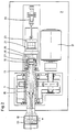
- Figur 1 den erfindungsgemäßen Auf- und/oder Abwickelhaspel in Betriebsstellung,
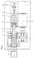
- Figur 2 den Haspel nach Fig. 1 im entspannten Zustand und
- Figur 3 den Haspel nach Fig. 1 im aus dem Coil ausgefahrenen Zustand.
- Fig. 1 ist ein Haspel 1 zu entnehmen, der sowohl zum Auf- als auch zum Abwickeln von Walzband geeignet ist. Der Haspel 1 weist ein, auf einen Grundrahmen 2 montiertes Haspelgehäuse 3 auf. Im Ständer 4 des Haspelgehäuses 3 sitzen Wälzlager 5, in denen drehbar axial unverschiebbar eine Antriebs- Hohlwelle 6 gelagert ist. In der Antriebs- Hohlwelle 6 ist eine als Vielkeilwelle ausgebildete Haspelwelle 7 axial verschiebbar drehfest geführt. Die Keile 8 der Haspelwelle 7 greifen in entsprechende Nute 9 in der Antriebs-Hohlwelle 6 ein.
- Am freien Ende der Haspelwelle 7 sind keilförmige Gleitflächen 10 angeordnet, auf denen sich die Segmente 11 der Haspeltrommel 12 abstützen. In der Haspelwelle 7 ist ein Stempel 13 geführt. Diese Führung erlaubt eine relative axiale Verschiebung zwischen der Haspelwelle 7 und dem Stempel 13. Über einen Anschlußflansch 14 ist der Stempel 13 mit den Segmenten 11 verbunden. Durch axiales Verschieben der Haspelwelle 7 werden, bei in axialer Richtung feststehendem Stempel 13, die keilförmigen Gleitflächen 10 gegenüber den Segmenten 11 hin und her bewegt, so daß die Haspeltrommel 12 gespreizt bzw. entspreizt wird.
- Am der Haspeltrommel 12 abgewandten Ende der Haspelwelle 7 weist diese einen den Außendurchmesser des Stempels 13 übersteigenden Innendurchmesser auf. In dem freien Raum zwischen dem Stempel 13 und der Haspelwelle 7 ist eine Druckfeder 15 eingelassen, die sich einerseits an der Haspelwelle 7 und andererseits an einem Kopf 16 des Stempels 13 abstützt. Durch Federkraft werden die Segmente 11 bei axial feststehendem Stempel 13 über die Haspelwelle 7 in Spreizstellung gehalten.
- Der Drehantrieb der Haspeltrommel 12 erfolgt vom Motor 17 aus über die Kupplung 18, das Getriebe 19, das auf der Antriebs-Hohlwelle 6 fest sitzende Zahnrad 20 und die Haspelwelle 7.
- Entspreizt werden kann die Haspeltrommel 12 durch axiales Verschieben der Haspelwelle 7 gegen die Kraft der Druckfeder 15. Gleichzeitig soll der Stempel 13 axial feststehen. Das bringt den Vorteil mit sich, daß auch die Segmente 11 beim Spreiz - bzw. Entspreizvorgang axial feststehen. Dadurch entsteht beim Coilwechsel kein zusätzlicher Bandmittenversatz. Der drehfest jedoch axial verschiebbar angeordnete Stellantrieb 21 bewirkt die Entspreizbeaufschlagung der Haspelwelle 7. Der Stellantrieb 21 ist über einen Schlitten 22 mit dem Grundrahmen 2 verbunden. Der Stellantrieb 21 besteht aus dem Zylinder 23, in dem ein Kolben 24 geführt ist. Am freien Ende der Kolbenstange 25 ist ein Kopf 26 vorgesehen, der dem Kopf 16 des Stempels 13 gegenübersteht.
- Am Zylinder 23 ist ein topfartiger Ansatz 27 montiert, dessen Ränder über Drehbewegungen aufnehmende und in axialer Richtung kraftschlüssig koppelnde Lager 28 mit dem der Haspeltrommel 12 abgewandten Ende der Haspelwelle 7 verbunden sind.
- Die Kolbenstange 25 setzt sich von dem dem Kopf 26 abgewandten Ende über den Kolben 24 und den Zylinder 23 hinaus fort und bildet dort den Angriffspunkt für die Kolbenstange 29 des auf dem Grundrahmen 2 fest montierten Verschiebeantriebs 30.
- In der Betriebsstellung (Fig. 1) wird die Haspeltrommel 12 vom Motor 17 angetrieben. Der Kopf 26 am Stellantrieb 21 ist vom Kopf 16 des Stempels 13 getrennt. Die Haspeltrommel 12 ist durch die Druckfeder 15 gespannt. In dieser Stellung kann der Verschiebeantrieb 30 über den axial verschiebbaren Stellantrieb 21 auf die Haspelwelle 7 und den Stempel 13 derart einwirken, daß die Haspeltrommel 12 während des Betriebes exakt auf die Bandmitte ausgerichtet ist, ohne daß eine Spreizbewegung durchgeführt wird.
- In der Entspreizstellung (Fig. 2) ist der Motor 17 gestoppt. Durch Beaufschlagung des Stellantriebes 21 soll die Haspelwelle 7 über den topfartigen Ansatz 27 axial zum Stellantrieb 21 hin bewegt werden. Damit der Stempel 13 jedoch axial in Ruhe verbleibt, wird der Verschiebeantrieb 30 entsprechend gegensinnig zum Stellantrieb 21 beaufschlagt. Der Verschiebeantrieb 30 wird axial in dem Maße verschoben, wie der Zylinder 23 des Stellantriebs 31 verschoben wird. Dadurch verbleibt die Haspelwelle 7 und der Stempel 13 vorerst axial in Ruhe. Sobald der Kopf 26 des Stellantriebes 21 und der Kopf 16 des Stempels 13 miteinander Kontakt haben, wird der Verschiebeantrieb 30 abgeschaltet. Dadurch verbleibt der Stempel 13 weiterhin in Ruhe, während bei weiterer Beaufschlagung des Stellantriebes 21 die Haspelwelle 7 axial zum Stellantrieb 21 hin bewegt wird. Die relative Verschiebung zwischen Haspelwelle 7 und Stempel 13 bewirkt die Entspreizbewegung der Segmente 11.
- Fig. 3 zeigt die aus dem Coil 31 ausgefahrene Haspeltrommel 12. Der Stellantrieb 21 steht weiterhin in Entspreizstellung, während der Verschiebeantrieb 30 den Stellantrieb 21 auf dem Schlitten 22 axial verschoben hat. Zusammen mit dem Stellantrieb 21 wurde über den topfartigen Ansatz 27 die Haspelwelle 7, der Stempel 13 und damit die Haspeltrommel 12 axial aus dem Coil 31 herausgezogen.
- Der erfindungsgemäße Auf- und/oder Abwickelhaspel eignet sich hervorragend für den Betrieb von Doppelkonushaspeln mit Bandmittenregelung. Für den Aufbau eines Doppelkonushaspels müssen lediglich zwei Auf-und/oder Abwickelhaspel nach der Erfindung spiegelbildlich zueinander montiert werden. Dabei ist es auch möglich, eine der Doppelkonushälften ohne den Drehantrieb 17 bis 20 auszuführen.
- Es besteht auch die Möglichkeit, beim Entspannen der Haspeltrommel 12 die Haspelwelle 7 axial festzusetzen und den Stempel 13 axial zu bewegen. Der dadurch bei der Entspreiz- bzw. Spreizbewegung entstehende Bandmittenversatz müßte ständig durch den Verschiebeantrieb 30 ausgeglichen werden.
-
- 1. Haspel
- 2. Grundrahmen
- 3. Haspelgehäuse
- 4. Ständer
- 5. Wälzlager
- 6. Antriebs-Hohlwelle
- 7. Haspelwelle
- 8. Keile
- 9. Nute
- 10. keilförmige Gleitflächen
- 11. Segmente
- 12. Haspeltrommel
- 13. Stempel
- 14. Anschlußflansch
- 15. Druckfeder
- 16. Kopf
- 17. Motor
- 18. Kupplung
- 19. Getriebe
- 20. Zahnrad
- 21. Stellantrieb
- 22. Schlitten
- 23. Zylinder
- 24. Kolben
- 25. Kolbenstange
- 26. Kopf
- 27. topfartiger Ansatz
- 28. Lager
- 29. Kolbenstange
- 30. Verschiebeantrieb
- 31. Coil
Claims (8)
dadurch gekennzeichnet,
dadurch gekennzeichnet,
daß die Haspelwelle (7) in einer im Haspelgehäuse (3) drehbar, axial unverschiebbar gelagerten (5) Antriebshohlwelle (6) axial verschiebbar und vermittels von in Nute (9) eingreifenden Keilen (8) drehfest angeordnet ist, und daß die Antriebshohlwelle (6) mit einem Zahnrad (20) versehen ist, in das ein Antriebszahnrad eines ortsfesten Getriebes (9) eingreift.
dadurch gekennzeichnet,
daß der Stellantrieb (21) einen topfartigen Ansatz (27) aufweist, dessen Rand das der Haspeltrommel (12) abgewandte Ende der Haspelwelle (7) umgreift und an diesem Ende so gelagert ist, daß praktisch keine Momente übertragen werden, in axialer Richtung jedoch Kraftschluß herrscht, so daß eine die Drehung der Haspelwelle (7) aufnehmende axiale Kupplung bewirkt wird, und daß der Verschiebeantrieb (30) am Stellantrieb (21) angreift und über diesen auf die Haspelwelle (7) einwirkt.
dadurch gekennzeichnet,
daß gegenüber dem Haspelgehäuse (3) der Stellantrieb (21) axial verschiebbar und der Verschiebeantrieb (30) ortsfest angeordnet sind.
dadurch gekennzeichnet,
daß die Kolbenstange (25) des Stellantriebes (24) und die Kolbenstange (29) des Verschiebeantriebes (30) miteinander verbunden sind.
dadurch gekennzeichnet,
daß die Kolben des Stellantriebes (21) und des Verschiebeantriebes (30) auf einer gemeinsamen Kolbenstange sitzen.
dadurch gekennzeichnet,
daß der topfartige Ansatz (27) des Stellantriebes (21) an dessen Zylinder (23) angesetzt ist.
dadurch gekennzeichnet,
daß im gespreizten Zustand der Haspeltrommel (21) der Kopf (26) des Stellantriebes (21) von dem Kopf (16) des Stempels (13) abgehoben ist.
Applications Claiming Priority (2)
| Application Number | Priority Date | Filing Date | Title |
|---|---|---|---|
| DE19853502452 DE3502452A1 (de) | 1985-01-25 | 1985-01-25 | Auf- und/oder abwickelhaspel fuer walzband |
| DE3502452 | 1985-01-25 |
Publications (3)
| Publication Number | Publication Date |
|---|---|
| EP0188795A2 EP0188795A2 (de) | 1986-07-30 |
| EP0188795A3 EP0188795A3 (en) | 1987-04-01 |
| EP0188795B1 true EP0188795B1 (de) | 1989-04-19 |
Family
ID=6260742
Family Applications (1)
| Application Number | Title | Priority Date | Filing Date |
|---|---|---|---|
| EP85116415A Expired EP0188795B1 (de) | 1985-01-25 | 1985-12-21 | Auf- und/oder Abwickelhaspel für Walzband |
Country Status (3)
| Country | Link |
|---|---|
| EP (1) | EP0188795B1 (de) |
| JP (1) | JPH069709B2 (de) |
| DE (2) | DE3502452A1 (de) |
Families Citing this family (9)
| Publication number | Priority date | Publication date | Assignee | Title |
|---|---|---|---|---|
| DE3836195A1 (de) * | 1988-10-24 | 1990-04-26 | Windmoeller & Hoelscher | Vorrichtung zum aufwickeln von materialbahnen auf wickelhuelsen |
| AT399302B (de) * | 1992-08-31 | 1995-04-25 | Voest Alpine Ind Anlagen | Haspel zum aufwickeln eines blechbandes |
| IT1298225B1 (it) * | 1998-02-11 | 1999-12-20 | Finsid S R L | Albero espansibile a scorrimento montato a sbalzo |
| ES2183689B1 (es) * | 2000-09-12 | 2004-02-01 | Torres Martinez M | Empalmador automatico de bandas laminares procedentes de bobinas de alimentacion. |
| DE102005031265A1 (de) | 2005-07-05 | 2007-01-18 | Sms Demag Ag | Spreizbarer Haspeldorn |
| DE102007030459A1 (de) | 2007-06-29 | 2009-01-08 | Sms Demag Ag | Spreizbarer Haspeldorn |
| CN102671999A (zh) * | 2012-05-09 | 2012-09-19 | 中国重型机械研究院有限公司 | 一种高刚性外支撑装置 |
| CN106364951B (zh) * | 2016-08-30 | 2018-02-06 | 安徽省中阳管业有限公司 | 一种可以根据钢带直径调节宽度的钢带放卷装置 |
| CN110723599A (zh) * | 2019-12-19 | 2020-01-24 | 广东含元工业技术有限公司 | 一种卷筒装置 |
Family Cites Families (5)
| Publication number | Priority date | Publication date | Assignee | Title |
|---|---|---|---|---|
| DE956214C (de) * | 1955-06-14 | 1957-01-17 | Achenbach Soehne Ges Mit Besch | Einrichtung zum axialen Einstellen eines Wickelbundes bei einer Wickelvorrichtung fuer bandartiges Gut, insbesondere fuer Baender aus Metall |
| DE1136182B (de) * | 1960-11-18 | 1962-09-06 | Schmitz Walzmasch | Aus zwei spiegelgleichen Haelften bestehende Abhaspelvorrichtung fuer Bandbunde |
| DE2727819A1 (de) * | 1977-06-21 | 1979-01-18 | Achenbach Buschhuetten Gmbh | Haspeleinrichtung fuer bandbearbeitungsmaschinen |
| DE2818042A1 (de) * | 1978-04-25 | 1979-11-08 | Schloemann Siemag Ag | Verfahren zum betrieb eines walzband-haspels sowie walzband-haspel zur ausuebung des verfahrens |
| DE3028607A1 (de) * | 1980-07-28 | 1982-02-25 | Schloemann-Siemag AG, 4000 Düsseldorf | Auf- und/oder abwickelhaspel fuer walzband |
-
1985
- 1985-01-25 DE DE19853502452 patent/DE3502452A1/de not_active Withdrawn
- 1985-12-21 DE DE8585116415T patent/DE3569488D1/de not_active Expired
- 1985-12-21 EP EP85116415A patent/EP0188795B1/de not_active Expired
-
1986
- 1986-01-23 JP JP61011217A patent/JPH069709B2/ja not_active Expired - Fee Related
Also Published As
| Publication number | Publication date |
|---|---|
| JPH069709B2 (ja) | 1994-02-09 |
| DE3502452A1 (de) | 1986-07-31 |
| DE3569488D1 (en) | 1989-05-24 |
| EP0188795A2 (de) | 1986-07-30 |
| JPS61176420A (ja) | 1986-08-08 |
| EP0188795A3 (en) | 1987-04-01 |
Similar Documents
| Publication | Publication Date | Title |
|---|---|---|
| DE2944983C2 (de) | Spindelstock für eine Universal-Fräs- und Bohrmaschine | |
| EP0188795B1 (de) | Auf- und/oder Abwickelhaspel für Walzband | |
| EP0440859B1 (de) | Antriebsrolleneinheit | |
| DE4312420C2 (de) | Waschvorrichtung für Zylinder einer Druckmaschine | |
| EP0221373B1 (de) | Wendehaspel | |
| DE20002915U1 (de) | Brems- und/oder Klemmvorrichtung für Führungen | |
| DE19621171A1 (de) | Direkt angetriebener Haspel | |
| AT500931A1 (de) | Punktschweisszange | |
| DE4140477A1 (de) | Verfahren zum abrollen von in form eines bandes angeordneten werbeanzeigen und vorrichtung zur durchfuehrung des verfahrens | |
| EP0002429A1 (de) | Aufwickelhaspel zum gleichzeitigen Aufwickeln von wenigstens zwei Bandstreifen | |
| DE2338490C2 (de) | Vorrichtung zum Abstreifen von Hohlkörpern von einem Preßstempel | |
| DE3642743C2 (de) | ||
| DE1574637C3 (de) | Einrichtung (Bandlaufwerk) zur Bewegung eines sich zwischen einer Abwickelspule und einer Aufwickelspule erstreckenden Bandes, insbesondere eines Magnetbandes | |
| DE1940414C3 (de) | Walzgerüst mit einer Einrichtung zum Walzenwechsel | |
| DE2905631C2 (de) | Walzgerüst mit mindestens einer von einer losen drehbaren Hülse umgebenden Stützwalze | |
| DE3729289C2 (de) | ||
| DE2818840C2 (de) | Zustelleinrichtung für die Schleifbearbeitung von planen oder sphärischen Flächen | |
| DE2556444A1 (de) | Vorschubeinrichtung fuer stab- oder bandfoermiges material | |
| EP0326805B1 (de) | Walzgerüst mit Verschiebeeinrichtung | |
| DE2642162A1 (de) | Walzwerk zum walzen eines kontinuierlichen blocks | |
| DE2835476B1 (de) | Vorrichtung zum Zufuehren von Band,insbesondere Blechband,von einem Coil zu einer Verarbeitungsmaschine | |
| DE102009042441A1 (de) | Ringpresse mit Torque-Motor | |
| EP0794021B1 (de) | Vorrichtung zum Nachschleifen der in Warmbandwalzgerüsten eingebauten Walzen | |
| DE1804781A1 (de) | Rundknetmaschine | |
| DE2623765A1 (de) | Axialkolbenmaschine |
Legal Events
| Date | Code | Title | Description |
|---|---|---|---|
| PUAI | Public reference made under article 153(3) epc to a published international application that has entered the european phase |
Free format text: ORIGINAL CODE: 0009012 |
|
| 17P | Request for examination filed |
Effective date: 19860116 |
|
| AK | Designated contracting states |
Kind code of ref document: A2 Designated state(s): BE DE FR GB IT NL |
|
| PUAL | Search report despatched |
Free format text: ORIGINAL CODE: 0009013 |
|
| AK | Designated contracting states |
Kind code of ref document: A3 Designated state(s): BE DE FR GB IT NL |
|
| 17Q | First examination report despatched |
Effective date: 19880921 |
|
| GRAA | (expected) grant |
Free format text: ORIGINAL CODE: 0009210 |
|
| STAA | Information on the status of an ep patent application or granted ep patent |
Free format text: STATUS: THE PATENT HAS BEEN GRANTED |
|
| AK | Designated contracting states |
Kind code of ref document: B1 Designated state(s): BE DE FR GB IT NL |
|
| REF | Corresponds to: |
Ref document number: 3569488 Country of ref document: DE Date of ref document: 19890524 |
|
| GBT | Gb: translation of ep patent filed (gb section 77(6)(a)/1977) | ||
| ET | Fr: translation filed | ||
| ITF | It: translation for a ep patent filed | ||
| PLBI | Opposition filed |
Free format text: ORIGINAL CODE: 0009260 |
|
| 26 | Opposition filed |
Opponent name: MANNESMANN AKTIENGESELLSCHAFT Effective date: 19900123 |
|
| NLR1 | Nl: opposition has been filed with the epo |
Opponent name: MANNESMANN AKTIENGESELLSCHAFT. |
|
| PG25 | Lapsed in a contracting state [announced via postgrant information from national office to epo] |
Ref country code: NL Effective date: 19900701 |
|
| NLV4 | Nl: lapsed or anulled due to non-payment of the annual fee | ||
| ITTA | It: last paid annual fee | ||
| PLBG | Opposition deemed not to have been filed |
Free format text: ORIGINAL CODE: 0009274 |
|
| 26D | Opposition deemed not to have been filed | ||
| PGFP | Annual fee paid to national office [announced via postgrant information from national office to epo] |
Ref country code: FR Payment date: 19961120 Year of fee payment: 12 |
|
| PGFP | Annual fee paid to national office [announced via postgrant information from national office to epo] |
Ref country code: GB Payment date: 19961213 Year of fee payment: 12 |
|
| PGFP | Annual fee paid to national office [announced via postgrant information from national office to epo] |
Ref country code: BE Payment date: 19961219 Year of fee payment: 12 |
|
| PG25 | Lapsed in a contracting state [announced via postgrant information from national office to epo] |
Ref country code: GB Free format text: LAPSE BECAUSE OF NON-PAYMENT OF DUE FEES Effective date: 19971221 |
|
| PG25 | Lapsed in a contracting state [announced via postgrant information from national office to epo] |
Ref country code: FR Free format text: THE PATENT HAS BEEN ANNULLED BY A DECISION OF A NATIONAL AUTHORITY Effective date: 19971231 Ref country code: BE Free format text: LAPSE BECAUSE OF NON-PAYMENT OF DUE FEES Effective date: 19971231 |
|
| BERE | Be: lapsed |
Owner name: SMS SCHLOEMANN-SIEMAG A.G. Effective date: 19971231 |
|
| GBPC | Gb: european patent ceased through non-payment of renewal fee |
Effective date: 19971221 |
|
| REG | Reference to a national code |
Ref country code: FR Ref legal event code: ST |
|
| RAP2 | Party data changed (patent owner data changed or rights of a patent transferred) |
Owner name: SMS DEMAG AG |
|
| PGFP | Annual fee paid to national office [announced via postgrant information from national office to epo] |
Ref country code: DE Payment date: 20021218 Year of fee payment: 18 |
|
| PG25 | Lapsed in a contracting state [announced via postgrant information from national office to epo] |
Ref country code: DE Free format text: LAPSE BECAUSE OF NON-PAYMENT OF DUE FEES Effective date: 20040701 |
|
| RIN2 | Information on inventor provided after grant (corrected) |
Inventor name: MOOS, WOLFGANG Inventor name: ROTHENPIELER, MANFRED |
|
| RAP2 | Party data changed (patent owner data changed or rights of a patent transferred) |
Owner name: SMS SIEMAG AG |
|
| RAP2 | Party data changed (patent owner data changed or rights of a patent transferred) |
Owner name: SMS GROUP GMBH |