EP0188960A1 - Optischer Positionsdetektionskodierer - Google Patents
Optischer Positionsdetektionskodierer Download PDFInfo
- Publication number
- EP0188960A1 EP0188960A1 EP85402591A EP85402591A EP0188960A1 EP 0188960 A1 EP0188960 A1 EP 0188960A1 EP 85402591 A EP85402591 A EP 85402591A EP 85402591 A EP85402591 A EP 85402591A EP 0188960 A1 EP0188960 A1 EP 0188960A1
- Authority
- EP
- European Patent Office
- Prior art keywords
- opto
- electronic
- reader
- micro
- light
- Prior art date
- Legal status (The legal status is an assumption and is not a legal conclusion. Google has not performed a legal analysis and makes no representation as to the accuracy of the status listed.)
- Granted
Links
- 230000003287 optical effect Effects 0.000 title claims abstract description 33
- 238000001514 detection method Methods 0.000 title 1
- 239000013307 optical fiber Substances 0.000 claims abstract description 24
- 230000005693 optoelectronics Effects 0.000 claims description 42
- 239000000835 fiber Substances 0.000 claims description 25
- 230000005540 biological transmission Effects 0.000 claims description 21
- 238000005516 engineering process Methods 0.000 claims description 4
- 230000001131 transforming effect Effects 0.000 claims description 3
- 230000003321 amplification Effects 0.000 claims description 2
- 238000003199 nucleic acid amplification method Methods 0.000 claims description 2
- 238000007493 shaping process Methods 0.000 claims description 2
- 230000005284 excitation Effects 0.000 claims 1
- 230000002457 bidirectional effect Effects 0.000 abstract 1
- 229920000297 Rayon Polymers 0.000 description 6
- 239000002964 rayon Substances 0.000 description 6
- 235000021183 entrée Nutrition 0.000 description 3
- 101100536354 Drosophila melanogaster tant gene Proteins 0.000 description 2
- 241001080024 Telles Species 0.000 description 2
- 230000004913 activation Effects 0.000 description 2
- 239000002775 capsule Substances 0.000 description 2
- 230000005855 radiation Effects 0.000 description 2
- 241000287107 Passer Species 0.000 description 1
- 240000008042 Zea mays Species 0.000 description 1
- XAGFODPZIPBFFR-UHFFFAOYSA-N aluminium Chemical compound [Al] XAGFODPZIPBFFR-UHFFFAOYSA-N 0.000 description 1
- 229910052782 aluminium Inorganic materials 0.000 description 1
- 230000000712 assembly Effects 0.000 description 1
- 238000000429 assembly Methods 0.000 description 1
- 238000012550 audit Methods 0.000 description 1
- 239000004020 conductor Substances 0.000 description 1
- 239000000470 constituent Substances 0.000 description 1
- 238000006073 displacement reaction Methods 0.000 description 1
- 230000005611 electricity Effects 0.000 description 1
- 238000004146 energy storage Methods 0.000 description 1
- 230000004907 flux Effects 0.000 description 1
- 230000002093 peripheral effect Effects 0.000 description 1
- 230000008054 signal transmission Effects 0.000 description 1
- 239000013589 supplement Substances 0.000 description 1
Images
Classifications
-
- G—PHYSICS
- G01—MEASURING; TESTING
- G01D—MEASURING NOT SPECIALLY ADAPTED FOR A SPECIFIC VARIABLE; ARRANGEMENTS FOR MEASURING TWO OR MORE VARIABLES NOT COVERED IN A SINGLE OTHER SUBCLASS; TARIFF METERING APPARATUS; MEASURING OR TESTING NOT OTHERWISE PROVIDED FOR
- G01D5/00—Mechanical means for transferring the output of a sensing member; Means for converting the output of a sensing member to another variable where the form or nature of the sensing member does not constrain the means for converting; Transducers not specially adapted for a specific variable
- G01D5/26—Mechanical means for transferring the output of a sensing member; Means for converting the output of a sensing member to another variable where the form or nature of the sensing member does not constrain the means for converting; Transducers not specially adapted for a specific variable characterised by optical transfer means, i.e. using infrared, visible, or ultraviolet light
- G01D5/32—Mechanical means for transferring the output of a sensing member; Means for converting the output of a sensing member to another variable where the form or nature of the sensing member does not constrain the means for converting; Transducers not specially adapted for a specific variable characterised by optical transfer means, i.e. using infrared, visible, or ultraviolet light with attenuation or whole or partial obturation of beams of light
- G01D5/34—Mechanical means for transferring the output of a sensing member; Means for converting the output of a sensing member to another variable where the form or nature of the sensing member does not constrain the means for converting; Transducers not specially adapted for a specific variable characterised by optical transfer means, i.e. using infrared, visible, or ultraviolet light with attenuation or whole or partial obturation of beams of light the beams of light being detected by photocells
- G01D5/347—Mechanical means for transferring the output of a sensing member; Means for converting the output of a sensing member to another variable where the form or nature of the sensing member does not constrain the means for converting; Transducers not specially adapted for a specific variable characterised by optical transfer means, i.e. using infrared, visible, or ultraviolet light with attenuation or whole or partial obturation of beams of light the beams of light being detected by photocells using displacement encoding scales
- G01D5/34707—Scales; Discs, e.g. fixation, fabrication, compensation
- G01D5/34715—Scale reading or illumination devices
- G01D5/34723—Scale reading or illumination devices involving light-guides
Definitions
- the present invention relates to optical coders for locating by transmitted light the position of a mobile element.
- Such an encoder comprises, on the one hand, a disc or a strip having several tracks, each with a succession of opaque zones and alternating fine transparent zones and, on the other hand, a reading assembly comprising, between others, a light source and one or more photodetectors which detect for each track whether an opaque zone or a transparent zone is present in front of the photodetector (s); the disc or the slide, on the one hand, and the reading assembly, on the other hand, are movable relative to each other either in rotation (case of the disc), or in translation (case of the strip).
- the photodetector (s) can be associated with an electronic unit for processing the signals emitted by the photodetector (s).
- conductors provide the electrical connections, in particular between the energy supply means, the opto-electronic system constituting reading assembly and the electronic signal processing unit.
- the present invention aims to make it possible to produce an optical coder for locating by transmitted-light the position of a mobile element remote from the electronic unit for processing the signals which represent this position, while avoiding any interference.
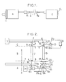
- FIG. 1 schematically illustrates the assembly of the optical position location coder provided with the improvements according to the invention, showing its three constituent units, namely the sensor, the optical transmission means and the module.
- Figure 2 illustrates the components of the three units illustrated in Figure 1.
- the invention is described below in a preferred embodiment applying to the identification of an angular position, the movable member of axis XX carrying, integral with it in rotation, a coded disc 1 with several concentric coded tracks , each with a succession of very fine zones which are alternately opaque and transparent in the peripheral direction.
- the encoder may also include an optical system between the second end 15 of the second optical fiber 13 and the micro-mirror 19, so as to adjust the light flux between the optical fiber 13 and the mirror 19 in the two directions of propagation, and an optical system (not shown), similar to the optical system 4, between the emitter 16 and the semi-transparent mirror 17.
- micro-mirror 19 and the actuation means 26 thereof can be constituted by a reflective micro-flap made of aluminum oscillating around its axis 19c, springs urging it normally in an extreme rest position 19b; on the other hand when the means 26 receive an electrical pulse from the first reader 10 excited by the radiation 12, the mirror is urged to pass to the other extreme position 19b by passing through the active position 19a.
- the reflective micro-flap and the associated control means can be produced, for example, as described in patent application No. 81 04778 (publication No. 2,478,352) filed on March 10, 1981 by CENTER ELECTRONIQUE HORLOGER SA, which allows to obtain them in the form of an element which can be controlled by pulses coming from the first reader 10 with a reduced expenditure of energy.
- the opto-electronic reader 10 comprises several photodetectors (at least one per track coded on the disc 1), an amplification and shaping circuit for the outputs of the photodetector (s) associated with each track, and a register with offset with parallel inputs (namely an input for each track) and with serial output, this single output being connected to the control means 26 of the micro-mirror 19.
- the electronic assembly of the opto-electronic reader 10 is produced in a technology which allows the reader to consume reduced electrical energy, in particular in a technology of the CMOS type.
- This reader 10 will therefore ultimately output, for each reading, a group of electrical pulses and pulse absences (in as many positions as there are coded tracks), an electrical pulse corresponding to a transparent area and a absence of impulse in an opaque zone of the track corresponding to the position in question.
- Successive readings are therefore manifested by successive groups of pulses and absence of pulses, such a pulse controlling, in response to a light pulse 12 having passed through a transparent zone of the disc 1, the passage of the micro-mirror 19 in position 19a, which causes radiation 2la which in return crosses the second optical fiber 13 and is partially returned by the semi-transparent element 17 as a light pulse 22a reaching the second reader 23 which in turn emits an electric pulse.
- the successive electrical pulses from the reader 23 are processed in the unit 24.
- the operation of the encoder according to the invention comprises a first commissioning period of the order of 0.5 to 1 second, in the case of a photovoltaic generation of current at 3a, but which may be of different duration for a other type of energy source.
- This commissioning period is followed by a first work cycle comprising the activation of the two opto-electronic transmitters 2 and 16 and the first opto-electronic reader 10, then, after locking the code in this reader 10, the serial transmission of the code by activation of the mirror 19 (by the means 26) and of the second opto-electronic reader 23.
- This work period lasts approximately 2 ms.
- optical fibers 7 and 13 and the associated opto-electronic systems are used for the remote transmission without risk of interference, on the one hand, of the light emitted by the diodes 2 and 16, the fiber 13 also serving when the light reflected by the micro-mirror 19 returns to position 19a.
- the bi-directional coupler 17 could be replaced by two bi-directional couplers arranged one between the surface 8 of the fiber 7 and the disc 1 and the other between the surface 15 of the fiber 13 and the micro-mirror. 19, or one could, while keeping the coupler 17, provide another similar coupler between the emitter 2 and the face 6 of the fiber 7; these two variants using two bi-directional couplers make it possible to eliminate the transmitter 16 and therefore to have a single transmitter in the module C.
- an electric inverter can be provided between the output of the shift register of the reader 10 and the actuating means or electrodes 26.
Landscapes
- Physics & Mathematics (AREA)
- General Physics & Mathematics (AREA)
- Optical Transform (AREA)
- Transmission And Conversion Of Sensor Element Output (AREA)
- Arrangements For Transmission Of Measured Signals (AREA)
- Optical Communication System (AREA)
- Length Measuring Devices By Optical Means (AREA)
Priority Applications (1)
| Application Number | Priority Date | Filing Date | Title |
|---|---|---|---|
| AT85402591T ATE40468T1 (de) | 1984-12-21 | 1985-12-20 | Optischer positionsdetektionskodierer. |
Applications Claiming Priority (2)
| Application Number | Priority Date | Filing Date | Title |
|---|---|---|---|
| FR8419713 | 1984-12-21 | ||
| FR8419713A FR2575285B1 (fr) | 1984-12-21 | 1984-12-21 | Codeur optique de reperage de position |
Publications (2)
| Publication Number | Publication Date |
|---|---|
| EP0188960A1 true EP0188960A1 (de) | 1986-07-30 |
| EP0188960B1 EP0188960B1 (de) | 1989-01-25 |
Family
ID=9310918
Family Applications (1)
| Application Number | Title | Priority Date | Filing Date |
|---|---|---|---|
| EP85402591A Expired EP0188960B1 (de) | 1984-12-21 | 1985-12-20 | Optischer Positionsdetektionskodierer |
Country Status (5)
| Country | Link |
|---|---|
| US (1) | US4739163A (de) |
| EP (1) | EP0188960B1 (de) |
| AT (1) | ATE40468T1 (de) |
| DE (1) | DE3567965D1 (de) |
| FR (1) | FR2575285B1 (de) |
Families Citing this family (11)
| Publication number | Priority date | Publication date | Assignee | Title |
|---|---|---|---|---|
| FR2583544B1 (fr) * | 1985-06-14 | 1987-09-04 | Mcb | Dispositif de lecture de code optique, notamment du type entierement integre |
| US4953933A (en) * | 1989-07-10 | 1990-09-04 | The Boeing Company | Optical encoder reading device |
| US5376785A (en) * | 1992-10-02 | 1994-12-27 | Chin; Philip K. | Optical displacement sensor utilizing optical diffusion |
| US5502514A (en) * | 1995-06-07 | 1996-03-26 | Nview Corporation | Stylus position sensing and digital camera with a digital micromirror device |
| US5831601A (en) * | 1995-06-07 | 1998-11-03 | Nview Corporation | Stylus position sensing and digital camera with a digital micromirror device |
| US5633691A (en) * | 1995-06-07 | 1997-05-27 | Nview Corporation | Stylus position sensing and digital camera with a digital micromirror device |
| US5612736A (en) * | 1995-06-07 | 1997-03-18 | Nview Corporation | Stylus position sensing and digital camera with a digital micromirror device |
| DE19549384C2 (de) * | 1995-06-19 | 1998-07-02 | Siemens Ag | Optischer Schalter |
| ES2311606T3 (es) * | 2001-06-05 | 2009-02-16 | Ngrid Intellectual Property Limited | Sensor optico contadores de uso general. |
| US7196320B1 (en) | 2005-03-14 | 2007-03-27 | Robert Rickenbach | Fiber optic encoder for position sensing |
| US20080040070A1 (en) * | 2006-08-11 | 2008-02-14 | Varco I/P, Inc. | Position Indicator for a Blowout Preventer |
Citations (2)
| Publication number | Priority date | Publication date | Assignee | Title |
|---|---|---|---|---|
| GB896092A (en) * | 1960-01-06 | 1962-05-09 | Gas Council | Improvements in or relating to integrating devices |
| GB2071896A (en) * | 1980-03-11 | 1981-09-23 | Centre Electron Horloger | Miniature display device |
Family Cites Families (6)
| Publication number | Priority date | Publication date | Assignee | Title |
|---|---|---|---|---|
| US3502414A (en) * | 1967-08-08 | 1970-03-24 | Bausch & Lomb | Optical electric system |
| JPS56111415A (en) * | 1980-02-08 | 1981-09-03 | Toshiba Corp | Multipoint time-division measuring device |
| JPS56111416A (en) * | 1980-02-08 | 1981-09-03 | Toshiba Corp | Multipoint time-division measuring device |
| JPS57135313A (en) * | 1981-02-16 | 1982-08-20 | Fanuc Ltd | Pulse encoder |
| US4430566A (en) * | 1981-04-21 | 1984-02-07 | Vibrac Corporation | Electro-optical angular displacement |
| GB2121252A (en) * | 1982-05-18 | 1983-12-14 | Marconi Co Ltd | Apparatus for indicating the position of a member |
-
1984
- 1984-12-21 FR FR8419713A patent/FR2575285B1/fr not_active Expired
-
1985
- 1985-12-19 US US06/810,721 patent/US4739163A/en not_active Expired - Fee Related
- 1985-12-20 DE DE8585402591T patent/DE3567965D1/de not_active Expired
- 1985-12-20 EP EP85402591A patent/EP0188960B1/de not_active Expired
- 1985-12-20 AT AT85402591T patent/ATE40468T1/de not_active IP Right Cessation
Patent Citations (2)
| Publication number | Priority date | Publication date | Assignee | Title |
|---|---|---|---|---|
| GB896092A (en) * | 1960-01-06 | 1962-05-09 | Gas Council | Improvements in or relating to integrating devices |
| GB2071896A (en) * | 1980-03-11 | 1981-09-23 | Centre Electron Horloger | Miniature display device |
Non-Patent Citations (2)
| Title |
|---|
| PATENTS ABSTRACTS OF JAPAN, vol. 5, no. 182 (P-90) [854], 20 novembre 1981 & 56 111 416 (TOKYO SHIBAURA DENKI K.K.) 03.09.1981 * |
| PATENTS ABSTRACTS OF JAPAN, vol. 5, no. 182 (P-90) [854], 20 novembre 1981 & JP - A - 56 111 415 (TOKYO SHIBAURA DENKI K.K.) 03.09.1981 * |
Also Published As
| Publication number | Publication date |
|---|---|
| FR2575285B1 (fr) | 1988-05-06 |
| EP0188960B1 (de) | 1989-01-25 |
| US4739163A (en) | 1988-04-19 |
| FR2575285A1 (fr) | 1986-06-27 |
| ATE40468T1 (de) | 1989-02-15 |
| DE3567965D1 (en) | 1989-03-02 |
Similar Documents
| Publication | Publication Date | Title |
|---|---|---|
| EP0709254B1 (de) | Elektronisches Informationsübertragungssystem auf stromführenden Leitungen, insbesonders für ein Kraftfahrzeug | |
| EP0188960B1 (de) | Optischer Positionsdetektionskodierer | |
| CA1283951C (fr) | Systeme pour la commande a distance d'un dispositif electrique par voieoptique | |
| FR2482390A1 (fr) | Systeme de transmission optique de signaux pour un vehicule automobile | |
| US20010013967A1 (en) | Multi-channel optical communication system that controls optical reflection for each channel and optical transmitting and receiving apparatuses therefor | |
| EP0189705B1 (de) | Optischer Positionsdetektionskodierer | |
| WO2002050565A1 (fr) | Anemometre a laser | |
| EP0222655A1 (de) | Analoger optischer Kodierer mit Positionserkennung | |
| EP0493169B1 (de) | Analysevorrichtung für interferometrische Mikroverschiebungssensoren | |
| EP0189706B1 (de) | Optisches Gerät zur Positionsortung | |
| FR2707394A1 (fr) | Elément et détecteur photosensibles pour la détection d'éclats lumineux. | |
| JP2791991B2 (ja) | 光スイッチ | |
| Yeatman et al. | Use of scanned detection in optical position encoders | |
| FR2698223A1 (fr) | Installation optoélectronique pour l'interconnexion de modules électroniques et connecteur optoélectronique correspondant. | |
| FR2520123A1 (fr) | Dispositif d'autotest pour equiper un systeme optronique | |
| FR2548796A1 (fr) | Dispositif optique pour determiner la position et la forme de la surface d'un objet | |
| JPS6155658B2 (de) | ||
| WO1999005758A1 (en) | Semiconductor laser power monitoring arrangements and method | |
| FR2589234A1 (fr) | Codeur optique de reperage de position du type analogique et element porteur de code pour un tel dispositif | |
| FR2589259A1 (fr) | Dispositif de raccordement modulaire des organes d'une installation industrielle a une unite de commande programmable | |
| US6603584B1 (en) | System and method for bi-directional optical communication | |
| EP1126639A1 (de) | Optisches bidirektionelles Übertragungsaufbauverfahren zwischen ein zentrales und ein entferntes Gerät | |
| FR2570836A1 (fr) | Dispositif a ligne a retard optique circulante | |
| JPH07122760A (ja) | 光モニタ用フォトダイオードおよびそれを用いたモジュール | |
| FR3155979A1 (fr) | Procede et dispositif d’alimentation et communication-bidirectionnelle sur au moins une fibre optique a au moins une longeur d’onde |
Legal Events
| Date | Code | Title | Description |
|---|---|---|---|
| PUAI | Public reference made under article 153(3) epc to a published international application that has entered the european phase |
Free format text: ORIGINAL CODE: 0009012 |
|
| AK | Designated contracting states |
Kind code of ref document: A1 Designated state(s): AT BE CH DE GB IT LI LU NL SE |
|
| 17P | Request for examination filed |
Effective date: 19860621 |
|
| 17Q | First examination report despatched |
Effective date: 19880316 |
|
| GRAA | (expected) grant |
Free format text: ORIGINAL CODE: 0009210 |
|
| AK | Designated contracting states |
Kind code of ref document: B1 Designated state(s): AT BE CH DE GB IT LI LU NL SE |
|
| PG25 | Lapsed in a contracting state [announced via postgrant information from national office to epo] |
Ref country code: IT Free format text: LAPSE BECAUSE OF FAILURE TO SUBMIT A TRANSLATION OF THE DESCRIPTION OR TO PAY THE FEE WITHIN THE PRESCRIBED TIME-LIMIT;WARNING: LAPSES OF ITALIAN PATENTS WITH EFFECTIVE DATE BEFORE 2007 MAY HAVE OCCURRED AT ANY TIME BEFORE 2007. THE CORRECT EFFECTIVE DATE MAY BE DIFFERENT FROM THE ONE RECORDED. Effective date: 19890125 Ref country code: NL Effective date: 19890125 Ref country code: SE Effective date: 19890125 Ref country code: AT Effective date: 19890125 |
|
| REF | Corresponds to: |
Ref document number: 40468 Country of ref document: AT Date of ref document: 19890215 Kind code of ref document: T |
|
| GBT | Gb: translation of ep patent filed (gb section 77(6)(a)/1977) | ||
| REF | Corresponds to: |
Ref document number: 3567965 Country of ref document: DE Date of ref document: 19890302 |
|
| NLV1 | Nl: lapsed or annulled due to failure to fulfill the requirements of art. 29p and 29m of the patents act | ||
| PLBE | No opposition filed within time limit |
Free format text: ORIGINAL CODE: 0009261 |
|
| STAA | Information on the status of an ep patent application or granted ep patent |
Free format text: STATUS: NO OPPOSITION FILED WITHIN TIME LIMIT |
|
| PG25 | Lapsed in a contracting state [announced via postgrant information from national office to epo] |
Ref country code: GB Effective date: 19891220 |
|
| PG25 | Lapsed in a contracting state [announced via postgrant information from national office to epo] |
Ref country code: LI Effective date: 19891231 Ref country code: LU Free format text: LAPSE BECAUSE OF NON-PAYMENT OF DUE FEES Effective date: 19891231 Ref country code: BE Effective date: 19891231 Ref country code: CH Effective date: 19891231 |
|
| 26N | No opposition filed | ||
| BERE | Be: lapsed |
Owner name: M.C.B. Effective date: 19891231 |
|
| GBPC | Gb: european patent ceased through non-payment of renewal fee | ||
| REG | Reference to a national code |
Ref country code: CH Ref legal event code: PL |
|
| PG25 | Lapsed in a contracting state [announced via postgrant information from national office to epo] |
Ref country code: DE Effective date: 19900901 |