EP0189005B1 - Conduit pour le transport des poudres ou matériaux en vrac secs et fins, et procédé pour son exploitation - Google Patents
Conduit pour le transport des poudres ou matériaux en vrac secs et fins, et procédé pour son exploitation Download PDFInfo
- Publication number
- EP0189005B1 EP0189005B1 EP85810614A EP85810614A EP0189005B1 EP 0189005 B1 EP0189005 B1 EP 0189005B1 EP 85810614 A EP85810614 A EP 85810614A EP 85810614 A EP85810614 A EP 85810614A EP 0189005 B1 EP0189005 B1 EP 0189005B1
- Authority
- EP
- European Patent Office
- Prior art keywords
- conveying
- fluidizing
- channel
- propulsion
- channels
- Prior art date
- Legal status (The legal status is an assumption and is not a legal conclusion. Google has not performed a legal analysis and makes no representation as to the accuracy of the status listed.)
- Expired
Links
Images



Classifications
-
- B—PERFORMING OPERATIONS; TRANSPORTING
- B65—CONVEYING; PACKING; STORING; HANDLING THIN OR FILAMENTARY MATERIAL
- B65G—TRANSPORT OR STORAGE DEVICES, e.g. CONVEYORS FOR LOADING OR TIPPING, SHOP CONVEYOR SYSTEMS OR PNEUMATIC TUBE CONVEYORS
- B65G53/00—Conveying materials in bulk through troughs, pipes or tubes by floating the materials or by flow of gas, liquid or foam
- B65G53/04—Conveying materials in bulk pneumatically through pipes or tubes; Air slides
- B65G53/16—Gas pressure systems operating with fluidisation of the materials
- B65G53/18—Gas pressure systems operating with fluidisation of the materials through a porous wall
- B65G53/20—Gas pressure systems operating with fluidisation of the materials through a porous wall of an air slide, e.g. a trough
-
- B—PERFORMING OPERATIONS; TRANSPORTING
- B65—CONVEYING; PACKING; STORING; HANDLING THIN OR FILAMENTARY MATERIAL
- B65G—TRANSPORT OR STORAGE DEVICES, e.g. CONVEYORS FOR LOADING OR TIPPING, SHOP CONVEYOR SYSTEMS OR PNEUMATIC TUBE CONVEYORS
- B65G53/00—Conveying materials in bulk through troughs, pipes or tubes by floating the materials or by flow of gas, liquid or foam
- B65G53/04—Conveying materials in bulk pneumatically through pipes or tubes; Air slides
- B65G53/16—Gas pressure systems operating with fluidisation of the materials
- B65G53/18—Gas pressure systems operating with fluidisation of the materials through a porous wall
Definitions
- the invention relates to a conveyor trough, which comprises at least one closed conveyor channel, one closed fluidizing channel with a feed tube, an intermediate fluidizing bottom and an outer tube and runs approximately horizontally, for the transport of dusty or fine-grained, dry bulk goods with a conveying area and a through a gas and liquid permeable material separated area for the supply of the fluidizing medium.
- the invention further relates to a method for operating the conveyor trough.
- Fluidizing channels are used, for example, in the cement, aluminum, chemical and food industries.
- the advantages over the mechanical conveying means are the simple construction, the low energy consumption and thus the better economy.
- the energy consumption of a 10% inclined conveyor channel for a transport distance of 100 m is between 0.04 KWh / t and 0.075 KWh / t.
- 1.5 to 3 KWh / t are required for thin-stream production over a length of 100 m, also with an existing gradient of up to 10%.
- the inventor has set himself the task of improving a conveyor trough of the type mentioned at the beginning and of specifying a method for operating the conveyor trough.
- the object is achieved by a device which is distinguished by the wording of claim 1.
- Advantageous further developments of the device according to the invention are characterized by the features of claims 2 to 9.
- the object is achieved by the features according to claim 10.
- the features of claim 11 characterize an advantageous inventive method variant.
- the conveyor trough is arranged horizontally.
- the overall constructive concept of the conveyor system may require that
- the conveyor trough is inclined slightly downwards, but gravity is not sufficient for an economic forward movement of the material to be conveyed, for example with a downward inclination of up to 2 °, or
- the conveyor trough has to be arranged slightly rising.
- the fluidizing base is designed in a known manner, it consists of fabrics (for example of cotton, cotton-plastic or polyester fibers), open-pore sintered metal or ceramic plates.
- a gas or a liquid is used as the propellant.
- the outer tube has, for example, depending on the capacity of the conveyor trough, a diameter of 5 to 80 cm and can just as well consist of a metal, in particular steel or aluminum, such as a pressure-resistant plastic.
- the outer tubes are preferably designed to be circular with respect to the cross section so that they can be assembled together with a simple coupling.
- the propulsion medium is introduced into the sealingly coupled outer tube and fills the interior space not occupied by the delivery channel or the delivery channels and the fluidization channel or the fluidization channels. From this communicating interior, the propulsion means can enter the delivery channel through the propulsion nozzles.
- the propulsion nozzles arranged in the lowermost region of the side wall of the conveyor channel (s) at a height of, for example, 1-5 cm are arranged uniformly with respect to the opposite side wall. If these nozzles were arranged alternately, the material to be conveyed would be thrown back and forth during the forward movement, which in addition to undesired additional dust generation would result in a lower efficiency. In practice it has proven to be advantageous to arrange the propulsion nozzles at a distance of 3 - 10 cm, all at the same level.
- the propulsion nozzles have an angle a of preferably 10 to 30 ° in the horizontal plane with respect to the side walls of the conveyor channel / channels or the pipes or the partition walls.
- the driving medium is thus fed into the material to be conveyed in such a way that the main component acts in the direction of conveyance.
- the pumped medium also penetrates towards the center of the pumping channel and thus creates an approximately laminar flow.
- the propulsion nozzles themselves are recessed from the corresponding walls, used as a separate part or molded. According to a variant, they are designed as nozzle inserts in the form of individual nozzles or nozzle strips.
- the preferably circular bore of the nozzles has a diameter of 1-2 mm, for example. However, vertical or almost vertical slots with a corresponding horizontal angle ⁇ can also be produced or appropriate nozzles can be used.
- Propulsion nozzles are preferably anchored in the fluidizing tray in a wide conveying channel. These can act on the material to be conveyed on their own or in cooperation with the propulsion nozzles arranged in the side walls of the conveying channel.
- the propulsion nozzles penetrating the fluidizing floor are anchored in a supporting floor. These propulsion nozzles have a vertical bore that merges into a slightly upward-pointing outlet bore. The outlet bore of these propulsion nozzles is not horizontal so that the fluidizing base is not rinsed and therefore worn out.
- the propulsion nozzles anchored in the support floor are regularly arranged in accordance with the structure of this floor and can be at a distance of 2 to 5 cm transversely to the conveying direction and 3 to 10 cm in the conveying direction.
- the propulsion nozzles therefore deviate only slightly from the direction of conveyance, usually at most 5 °, because the increasing deviation increases the energy consumption significantly.
- the fluidizing and propulsion medium are combined in the delivery channel, they expediently consist of the same material.
- the media can then easily come from the same drive unit, but they have to be brought into the conveyor trough in separate feed lines.
- the conveyor trough according to the invention is suitable for performing other functions in addition to pure transport for special uses.
- devices can be installed which heat or cool the material to be conveyed, separate or sift it, burn it and / or adsorb.
- appropriate devices are attached and the material is treated in the conveyor trough.
- the entire conveyor trough is designed so that no screws are necessary.
- the relatively low excess pressure is expediently generated with two pumps in the case of liquid propulsion media, and expediently with two fans in the case of gaseous propulsion media.
- the two different overpressures can also be generated by means of a pump or a blower.
- a relative negative pressure of, for example, 20 mm water pressure is preferably applied in the conveying channel or conveying channels and the dusty atmosphere is thus drawn off and fed to the cleaning.
- the device according to the invention is well suited for the transport of bulk goods from 100 kg to 1000 tons per hour.
- the conveyor trough 10 shown in FIGS. 1 and 2 is supported on a support structure 12.
- the material inlet 14 and the first element of the conveyor trough are formed in one piece.
- a blower for compressed air is arranged, which is used both as a fluidizing and as a propulsion medium.
- the blower 18 leads compressed air to the fluidizing plate, the blower 20 to the propulsion nozzles.
- the entry of air into the blower is characterized by arrows.
- the console 22 carrying the electric motor 16 and blower 18, 20 conceals the channel joint 24 in FIG. 1.
- a conventional coupling 26 is arranged over the channel joints 24, which ensures an airtight connection of the P elements of the conveyor channel.
- a closing element is coupled, which has a material outlet 28 at the bottom and an exhaust air opening 30 at the top.
- the conveyor trough shown in FIG. 3 has a conveyor channel 32 which is slightly more than 10 cm wide. In the upper region, this is adapted to the closed outer tube 34 and connected to it.
- a fluidizing channel 36 of equal width adjoins below the conveying channel 32, into which a supply line 38 for the fluidizing air opens.
- This feed line consists of tubes which are pushed into one another and which are provided with sealing rings 40.
- the horizontal fluidizing base 42 is arranged between the fluidizing and the conveying channel.
- the fluidizing base 42 consists of a fabric made of polyester fibers and is flanged and glued laterally over the entire length.
- a feed line 44 for the propulsion air opens into the outer tube 34.
- the supplied propulsion air fills the entire cavity 48 in the outer tube 34, which is not used by the delivery channel 32, the fluidizing channel 36 and the supply lines.
- propulsion nozzles 50 arranged in the lowermost region of the side walls 52 of the conveying channel 32, the propelling air enters the fluidized conveyed material and displaces it in the conveying direction.
- the propulsion nozzles 50 are recessed from the side wall 52 of the delivery channel 32. However, they can also be produced by injection molding or precision casting and used individually or as a bar.
- the propulsion air flowing through the cavity 38 and entering the propulsion nozzles 50 is characterized by an arrow 54.
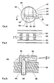
- a gutter joint 24 is shown in detail in FIG. 5.
- the circular outer tubes 34 of the conveyor trough are closed airtight in the connection area with a coupling 26.
- a passage 56 for the fluidizing air is formed in the fluidizing channel 36 in the region of the channel joint.
- the fluidizing base 42 is glued in this area, so that no fluidizing air can pass through.
- the material to be conveyed 46 is only indicated, but it is clearly visible that it flows over the gluing point of the fluidizing base 42 while forming a hump.
- FIGS. 6 and 7 differ from FIGS. 3 and 4 in that not one but a plurality of delivery channels 32 are formed. This is necessary because of the limited action of the propulsion nozzles 50 with respect to the width of the conveying channels 32. All propulsion nozzles 50 are fed by propulsion air from the communicating cavity 48.
- the fluidizing base 42 and the fluidizing channel 36 extend across the width of all delivery channels 32 and are not subdivided.
- propulsion nozzles 50 are arranged identically. With an alternating arrangement, the material to be conveyed would be thrown back and forth in the conveying channel 32 during the forward movement.
- the conveyor trough shown in FIGS. 8 and 9 is also designed for large production capacities.
- the approximately 50 cm wide conveying channel 32 has propulsion nozzles 50 arranged in the side wall 52 of the conveying channel 32 in accordance with FIGS. 3 and 4, but these are not shown for reasons of clarity.
- the fluidizing plate 42 is supported by a supporting plate 58.
- the cross section of this is wave-shaped, that is to say it has a plurality of fluidizing channels 36 running in the longitudinal direction of the conveying trough.
- Propulsion nozzles 60 with an angled bore are anchored in the support base in the contact surfaces of the fluidizing base 42 on the support base 58. These propulsion nozzles 60 are fed from the communicating cavity 48.
- the propulsion nozzles 60 do not run exactly in the conveying direction, but are turned off by the angle y.
- the angle y is approximately 5 °. In this way, propulsion nozzles 60 lying directly one behind the other do not blow.
- FIG. 10 shows an enlarged view of a propulsion nozzle 60 with an angled outlet bore 62.
- the axis of this bore leading to the outlet opening extends upwards by an angle ⁇ from the horizontal, so that the fluidizing base is not blown out.
- the angle ⁇ is 5 ° in the present case.
- a bulk profile 64 of bulk material is formed in front of each nozzle. Only this stowage profile 64 is shown in FIG. 10 and the remaining bulk material is omitted for the sake of simplicity.
- a pointed steel mandrel is inserted into them from below.
- the nozzle with the mandrel is then driven through the tissue forming the fluidizing base 42 and the support base 58 until the nozzle lies snugly on the fluidizing base 42.
- a brow 66 is formed in the support base 58, which tightly clamps the propulsion nozzle 60 used.
- FIG. 11 shows a comparative test for the power consumption when conveying cement as a function of the conveying path W, the amount conveyed being 40 t / h.
- a screw conveyor, labeled Sch obviously consumes the greatest output by far.
- the power consumption of a 10% inclined pneumatic conveyor trough is very small. However, it must be taken into account that the inclination requires a considerable amount of construction and takes up a lot of space.
- the power consumption of the device according to the invention in accordance with the variant from FIGS. 3 to 5 is designated by MFC. This power consumption is relatively small with little design effort, although the conveyor trough is arranged horizontally as with the screw conveyor.
Landscapes
- Engineering & Computer Science (AREA)
- Mechanical Engineering (AREA)
- Air Transport Of Granular Materials (AREA)
- Insulated Conductors (AREA)
- Control And Other Processes For Unpacking Of Materials (AREA)
- Chutes (AREA)
- Plural Heterocyclic Compounds (AREA)
- Disintegrating Or Milling (AREA)
- Ropes Or Cables (AREA)
Claims (11)
caractérisée
Priority Applications (1)
| Application Number | Priority Date | Filing Date | Title |
|---|---|---|---|
| AT85810614T ATE37848T1 (de) | 1985-01-15 | 1985-12-23 | Foerderrinne fuer den transport von staubfoermigen oder feinkoernigen, trockenen schuettguetern und ein verfahren zu deren betrieb. |
Applications Claiming Priority (2)
| Application Number | Priority Date | Filing Date | Title |
|---|---|---|---|
| CH177/85 | 1985-01-15 | ||
| CH17785 | 1985-01-15 |
Publications (2)
| Publication Number | Publication Date |
|---|---|
| EP0189005A1 EP0189005A1 (fr) | 1986-07-30 |
| EP0189005B1 true EP0189005B1 (fr) | 1988-10-12 |
Family
ID=4181016
Family Applications (1)
| Application Number | Title | Priority Date | Filing Date |
|---|---|---|---|
| EP85810614A Expired EP0189005B1 (fr) | 1985-01-15 | 1985-12-23 | Conduit pour le transport des poudres ou matériaux en vrac secs et fins, et procédé pour son exploitation |
Country Status (9)
| Country | Link |
|---|---|
| US (1) | US4812085A (fr) |
| EP (1) | EP0189005B1 (fr) |
| AT (1) | ATE37848T1 (fr) |
| AU (1) | AU587214B2 (fr) |
| CA (1) | CA1270283A (fr) |
| DE (1) | DE3565508D1 (fr) |
| FI (1) | FI82015C (fr) |
| NO (1) | NO161362C (fr) |
| ZA (1) | ZA859755B (fr) |
Families Citing this family (11)
| Publication number | Priority date | Publication date | Assignee | Title |
|---|---|---|---|---|
| US4818152A (en) * | 1986-10-14 | 1989-04-04 | Fuller Company | Apparatus for conveying hot finely divided material |
| GB8727701D0 (en) * | 1987-11-26 | 1987-12-31 | Hambro Machinery Ltd | Fluid distribution device |
| EP0353261A1 (fr) * | 1987-11-26 | 1990-02-07 | Hambro Machinery Limited | Appareil de transport et appareil de separation |
| AU607170B2 (en) * | 1987-12-02 | 1991-02-28 | Fuller Company | Apparatus for conveying hot finely divided material |
| EP0319596A1 (fr) * | 1987-12-07 | 1989-06-14 | Fuller Company | Dispositif pour le transport de matières pulvérulentes chaudes |
| RU2137692C1 (ru) * | 1998-11-05 | 1999-09-20 | Всероссийский научно-исследовательский институт механизации сельского хозяйства | Установка для транспортирования и активного вентилирования семян и зерна |
| RU2144898C1 (ru) * | 1998-11-11 | 2000-01-27 | Всероссийский научно-исследовательский институт механизации сельского хозяйства | Устройство для вентилирования и транспортирования сыпучих материалов |
| EP1623941A1 (fr) * | 2004-08-05 | 2006-02-08 | Alcan Technology & Management Ltd. | Dispositif et procédé de transport pneumatique de produits coulants dans une coulée épaisse |
| US20140270998A1 (en) * | 2013-03-14 | 2014-09-18 | Babcock Power Services, Inc. | Pneumatic conveyor fabric frames and mounts |
| FI20155245A7 (fi) * | 2015-04-07 | 2016-10-08 | Outotec Finland Oy | Pneumaattinen kuljetin |
| JP7069696B2 (ja) * | 2017-12-21 | 2022-05-18 | 住友金属鉱山株式会社 | 石灰石原料供給用シュート |
Family Cites Families (10)
| Publication number | Priority date | Publication date | Assignee | Title |
|---|---|---|---|---|
| US24716A (en) * | 1859-07-12 | Flesh-fork astd skimmer | ||
| USRE24716E (en) | 1959-10-06 | Air flow conveying system | ||
| US2805898A (en) * | 1955-01-18 | 1957-09-10 | Jr Edward A Willis | Fluid current conveyor for fragile articles |
| US2882097A (en) * | 1956-12-19 | 1959-04-14 | Arvid J Hamren | Air-conveyor |
| DE1150320B (de) * | 1957-09-11 | 1963-06-12 | Peters Ag Claudius | Pneumatische Foerderrinne fuer staubfoermige und feinkoernige Gueter |
| US4033555A (en) * | 1971-01-11 | 1977-07-05 | The Motch & Merryweather Machinery Company | Fluidized bed for treating granular material |
| CH614678A5 (fr) * | 1976-12-13 | 1979-12-14 | Alusuisse | |
| DD151726A1 (de) * | 1980-06-23 | 1981-11-04 | Wolfgang Michalik | Pneumatischer trogfoerderer fuer rieselfaehige und fluidisierbare massengueter |
| US4395165A (en) * | 1980-12-19 | 1983-07-26 | International Business Machine Corp. | Chip shuttle track |
| US4561806A (en) * | 1983-01-31 | 1985-12-31 | Precision Metal Fabricators, Inc. | Vertical single filer conveyor system |
-
1985
- 1985-12-20 ZA ZA859755A patent/ZA859755B/xx unknown
- 1985-12-23 EP EP85810614A patent/EP0189005B1/fr not_active Expired
- 1985-12-23 DE DE8585810614T patent/DE3565508D1/de not_active Expired
- 1985-12-23 AT AT85810614T patent/ATE37848T1/de not_active IP Right Cessation
- 1985-12-30 US US06/815,019 patent/US4812085A/en not_active Expired - Fee Related
-
1986
- 1986-01-02 AU AU51803/86A patent/AU587214B2/en not_active Ceased
- 1986-01-09 CA CA000499310A patent/CA1270283A/fr not_active Expired - Lifetime
- 1986-01-13 NO NO860087A patent/NO161362C/no unknown
- 1986-01-14 FI FI860169A patent/FI82015C/fi not_active IP Right Cessation
Also Published As
| Publication number | Publication date |
|---|---|
| FI860169L (fi) | 1986-07-16 |
| ZA859755B (en) | 1986-11-26 |
| FI860169A0 (fi) | 1986-01-14 |
| FI82015B (fi) | 1990-09-28 |
| AU5180386A (en) | 1986-07-24 |
| NO860087L (no) | 1986-07-16 |
| CA1270283A (fr) | 1990-06-12 |
| ATE37848T1 (de) | 1988-10-15 |
| NO161362C (no) | 1989-08-09 |
| NO161362B (no) | 1989-05-02 |
| US4812085A (en) | 1989-03-14 |
| DE3565508D1 (en) | 1988-11-17 |
| EP0189005A1 (fr) | 1986-07-30 |
| FI82015C (fi) | 1991-01-10 |
| AU587214B2 (en) | 1989-08-10 |
Similar Documents
| Publication | Publication Date | Title |
|---|---|---|
| EP1776301B1 (fr) | Dispositif et procede de transport pneumatique de produits en vrac dans le cadre d'un procede a flux dense | |
| EP0189005A1 (fr) | Conduit pour le transport des poudres ou matériaux en vrac secs et fins, et procédé pour son exploitation | |
| DE2657677B2 (de) | Verfahren und Vorrichtung zur pneumatischen Förderung von Schüttgütern, zähflieflenden Massen, Schlämmen o.dgl. in einer rohrförmigen Förderrinne | |
| DE1959172A1 (de) | Verfahren und Vorrichtung zur Saugluftfoerderung von Schuettgut | |
| EP0201671B1 (fr) | Ajutage pour l'introduction pneumatique de solides | |
| CH661909A5 (de) | Vorrichtung zum foerdern von staubfoermigen bis grobkoernigen schuettguetern. | |
| EP0439599A1 (fr) | Reacteur pour produits en vrac. | |
| DE1913708B2 (de) | Verfahren und Vorrichtung zum Trennen von körnigem Gut | |
| DE69108023T2 (de) | Verfahren zum Kühlen von aus Partikeln bestehendem Material, insbesondere von feinkörnigem Staub. | |
| DE2728124A1 (de) | Einrichtung zur abscheidung von staubfoermigen teilen aus einem luftstrom | |
| DE69704377T2 (de) | Rohrtrogartiger förderer für das pneumatische fördern von staubförmigem material | |
| DE3024567A1 (de) | Foerderrinne | |
| DE2157893C3 (de) | Hebe- und Förderanlage zum Entladen von Schiffen | |
| EP0059781A2 (fr) | Arrangement pour élever et convoyer pneumatiquement ou hydrauliquement des matières à transporter | |
| DE3408271C2 (de) | Vorrichtung zum pneumatischen Fördern von Schüttgütern | |
| DE3632494C1 (en) | Apparatus for transporting finely divided or granular material - mixtures of construction material (material to be conveyed) | |
| DE1175151B (de) | Pneumatische Vorrichtung zum Heben fester, koerniger Stoffe | |
| DE2816842C2 (de) | Einrichtung zum Fördern von kornförmigem Gut aus einem Behälter | |
| AT346771B (de) | Anordnung fuer ein pneumatisches entleeren von schuettgut aus boden- und anderen lagerplaetzen | |
| DE1197384B (de) | Vorrichtung zum Foerdern von pulverfoermigem oder feinkoernigem Gut | |
| DE3608337C1 (en) | Apparatus for transporting finely divided or granular material - mixtures of construction material - (material to be conveyed) | |
| DE1078046B (de) | Verfahren und Vorrichtung zum Foerdern von pulverfoermigem Material | |
| DE2354032C3 (de) | Vorrichtung zum Aufbauen eines FlieBbettes aus pulverförmigem oder feinkörnigem Material von konstantem Niveau und konstanter Zusammensetzung | |
| RU35791U1 (ru) | Установка для пневматической транспортировки сыпучих продуктов | |
| DE1556621A1 (de) | In Schuettgut absenkbares Mundstueck fuer einen pneumatischen Elevator zur Entladung,insbesondere von Schuettgutfrachtern |
Legal Events
| Date | Code | Title | Description |
|---|---|---|---|
| PUAI | Public reference made under article 153(3) epc to a published international application that has entered the european phase |
Free format text: ORIGINAL CODE: 0009012 |
|
| AK | Designated contracting states |
Kind code of ref document: A1 Designated state(s): AT BE CH DE FR GB IT LI NL SE |
|
| 17P | Request for examination filed |
Effective date: 19861229 |
|
| 17Q | First examination report despatched |
Effective date: 19870722 |
|
| ITF | It: translation for a ep patent filed | ||
| GRAA | (expected) grant |
Free format text: ORIGINAL CODE: 0009210 |
|
| AK | Designated contracting states |
Kind code of ref document: B1 Designated state(s): AT BE CH DE FR GB IT LI NL SE |
|
| REF | Corresponds to: |
Ref document number: 37848 Country of ref document: AT Date of ref document: 19881015 Kind code of ref document: T |
|
| GBT | Gb: translation of ep patent filed (gb section 77(6)(a)/1977) | ||
| REF | Corresponds to: |
Ref document number: 3565508 Country of ref document: DE Date of ref document: 19881117 |
|
| ET | Fr: translation filed | ||
| PLBE | No opposition filed within time limit |
Free format text: ORIGINAL CODE: 0009261 |
|
| STAA | Information on the status of an ep patent application or granted ep patent |
Free format text: STATUS: NO OPPOSITION FILED WITHIN TIME LIMIT |
|
| 26N | No opposition filed | ||
| ITTA | It: last paid annual fee | ||
| PGFP | Annual fee paid to national office [announced via postgrant information from national office to epo] |
Ref country code: FR Payment date: 19921111 Year of fee payment: 8 Ref country code: CH Payment date: 19921111 Year of fee payment: 8 |
|
| PGFP | Annual fee paid to national office [announced via postgrant information from national office to epo] |
Ref country code: DE Payment date: 19921116 Year of fee payment: 8 |
|
| PGFP | Annual fee paid to national office [announced via postgrant information from national office to epo] |
Ref country code: SE Payment date: 19921117 Year of fee payment: 8 Ref country code: AT Payment date: 19921117 Year of fee payment: 8 |
|
| PGFP | Annual fee paid to national office [announced via postgrant information from national office to epo] |
Ref country code: BE Payment date: 19921209 Year of fee payment: 8 |
|
| PGFP | Annual fee paid to national office [announced via postgrant information from national office to epo] |
Ref country code: GB Payment date: 19921214 Year of fee payment: 8 |
|
| PGFP | Annual fee paid to national office [announced via postgrant information from national office to epo] |
Ref country code: NL Payment date: 19921231 Year of fee payment: 8 |
|
| PG25 | Lapsed in a contracting state [announced via postgrant information from national office to epo] |
Ref country code: GB Effective date: 19931223 Ref country code: AT Effective date: 19931223 |
|
| PG25 | Lapsed in a contracting state [announced via postgrant information from national office to epo] |
Ref country code: SE Effective date: 19931224 |
|
| PG25 | Lapsed in a contracting state [announced via postgrant information from national office to epo] |
Ref country code: LI Effective date: 19931231 Ref country code: CH Effective date: 19931231 Ref country code: BE Effective date: 19931231 |
|
| BERE | Be: lapsed |
Owner name: SCHWEIZERISCHE ALUMINIUM A.G. Effective date: 19931231 |
|
| PG25 | Lapsed in a contracting state [announced via postgrant information from national office to epo] |
Ref country code: NL Effective date: 19940701 |
|
| NLV4 | Nl: lapsed or anulled due to non-payment of the annual fee | ||
| GBPC | Gb: european patent ceased through non-payment of renewal fee |
Effective date: 19931223 |
|
| PG25 | Lapsed in a contracting state [announced via postgrant information from national office to epo] |
Ref country code: FR Effective date: 19940831 |
|
| REG | Reference to a national code |
Ref country code: CH Ref legal event code: PL |
|
| PG25 | Lapsed in a contracting state [announced via postgrant information from national office to epo] |
Ref country code: DE Effective date: 19940901 |
|
| REG | Reference to a national code |
Ref country code: FR Ref legal event code: ST |
|
| EUG | Se: european patent has lapsed |
Ref document number: 85810614.9 Effective date: 19940710 |