EP0189018A1 - Fraiseuse à usiner des vilebrequins ou similaires - Google Patents
Fraiseuse à usiner des vilebrequins ou similaires Download PDFInfo
- Publication number
- EP0189018A1 EP0189018A1 EP85890015A EP85890015A EP0189018A1 EP 0189018 A1 EP0189018 A1 EP 0189018A1 EP 85890015 A EP85890015 A EP 85890015A EP 85890015 A EP85890015 A EP 85890015A EP 0189018 A1 EP0189018 A1 EP 0189018A1
- Authority
- EP
- European Patent Office
- Prior art keywords
- milling
- brake
- units
- milling machine
- gear
- Prior art date
- Legal status (The legal status is an assumption and is not a legal conclusion. Google has not performed a legal analysis and makes no representation as to the accuracy of the status listed.)
- Granted
Links
- 238000003801 milling Methods 0.000 title claims abstract description 114
- 238000003754 machining Methods 0.000 claims abstract description 12
- 238000005520 cutting process Methods 0.000 claims abstract description 5
- 238000006073 displacement reaction Methods 0.000 claims abstract description 4
- 230000000903 blocking effect Effects 0.000 claims 1
- 238000000034 method Methods 0.000 description 3
- 238000010276 construction Methods 0.000 description 2
- 238000004519 manufacturing process Methods 0.000 description 2
- 230000007812 deficiency Effects 0.000 description 1
- 230000002349 favourable effect Effects 0.000 description 1
- 230000006641 stabilisation Effects 0.000 description 1
- 238000011105 stabilization Methods 0.000 description 1
Images



Classifications
-
- B—PERFORMING OPERATIONS; TRANSPORTING
- B23—MACHINE TOOLS; METAL-WORKING NOT OTHERWISE PROVIDED FOR
- B23Q—DETAILS, COMPONENTS, OR ACCESSORIES FOR MACHINE TOOLS, e.g. ARRANGEMENTS FOR COPYING OR CONTROLLING; MACHINE TOOLS IN GENERAL CHARACTERISED BY THE CONSTRUCTION OF PARTICULAR DETAILS OR COMPONENTS; COMBINATIONS OR ASSOCIATIONS OF METAL-WORKING MACHINES, NOT DIRECTED TO A PARTICULAR RESULT
- B23Q11/00—Accessories fitted to machine tools for keeping tools or parts of the machine in good working condition or for cooling work; Safety devices specially combined with or arranged in, or specially adapted for use in connection with, machine tools
- B23Q11/0078—Safety devices protecting the operator, e.g. against accident or noise
- B23Q11/0092—Safety devices protecting the operator, e.g. against accident or noise actuating braking or stopping means
-
- B—PERFORMING OPERATIONS; TRANSPORTING
- B23—MACHINE TOOLS; METAL-WORKING NOT OTHERWISE PROVIDED FOR
- B23C—MILLING
- B23C3/00—Milling particular work; Special milling operations; Machines therefor
- B23C3/06—Milling crankshafts
-
- B—PERFORMING OPERATIONS; TRANSPORTING
- B23—MACHINE TOOLS; METAL-WORKING NOT OTHERWISE PROVIDED FOR
- B23Q—DETAILS, COMPONENTS, OR ACCESSORIES FOR MACHINE TOOLS, e.g. ARRANGEMENTS FOR COPYING OR CONTROLLING; MACHINE TOOLS IN GENERAL CHARACTERISED BY THE CONSTRUCTION OF PARTICULAR DETAILS OR COMPONENTS; COMBINATIONS OR ASSOCIATIONS OF METAL-WORKING MACHINES, NOT DIRECTED TO A PARTICULAR RESULT
- B23Q5/00—Driving or feeding mechanisms; Control arrangements therefor
- B23Q5/22—Feeding members carrying tools or work
- B23Q5/34—Feeding other members supporting tools or work, e.g. saddles, tool-slides, through mechanical transmission
- B23Q5/38—Feeding other members supporting tools or work, e.g. saddles, tool-slides, through mechanical transmission feeding continuously
- B23Q5/40—Feeding other members supporting tools or work, e.g. saddles, tool-slides, through mechanical transmission feeding continuously by feed shaft, e.g. lead screw
- B23Q5/402—Feeding other members supporting tools or work, e.g. saddles, tool-slides, through mechanical transmission feeding continuously by feed shaft, e.g. lead screw in which screw or nut can both be driven
-
- B—PERFORMING OPERATIONS; TRANSPORTING
- B23—MACHINE TOOLS; METAL-WORKING NOT OTHERWISE PROVIDED FOR
- B23C—MILLING
- B23C2210/00—Details of milling cutters
- B23C2210/50—Cutting inserts
- B23C2210/503—Cutting inserts mounted internally on the cutter
-
- B—PERFORMING OPERATIONS; TRANSPORTING
- B23—MACHINE TOOLS; METAL-WORKING NOT OTHERWISE PROVIDED FOR
- B23C—MILLING
- B23C2220/00—Details of milling processes
- B23C2220/68—Whirling
Definitions
- the invention relates to a milling machine for machining crankshafts or the like, with the feed for a round machining to the workpiece axis of concentric or eccentric cross sections correspondingly movable in a normal plane on the workpiece axis milling units, each having a rotatable tool drum for receiving annular, internal cutting cutter heads.
- Milling machines with two or more milling units and single or multiple knife heads as milling tools are used for the mass production of crankshafts or camshafts and the like. Like. Used and lead due to the simultaneous processing of several Cross sections at short processing times. Up to now, however, each of these milling units has been assigned its own milling carriage which applies the feed movement, which results in an inefficient machine design and space problems, in particular with regard to adequate workpiece support.
- the invention is therefore based on the object to eliminate these deficiencies and to provide a milling machine of the type described above is characterized by a comparatively simple and compact structure and by favorable control and drive conditions.
- the invention achieves this object in that the milling units, which are themselves displaceably guided in a manner known per se, can simultaneously be moved in a feed-ready manner by a common drive.
- the milling units can thus themselves take over the function of a slide, which means that the mechanical outlay can be reduced as desired and the common drive also enables the low-cost control and drive devices.
- the milling units can be used directly in the guides of the machine bed or a longitudinal slide, but they can also be arranged on a common milling slide with the associated guides and the drive for processing stationary workpieces.
- This milling slide therefore no longer needs to be a cross slide or the like composed of partial slides, but can e.g. be designed as a simple cross slide with the height of the milling units which can be moved so that a simple, robust machine design is ensured.
- the drive for the milling units has a screw gear, which has a drivable screw spindle, preferably a ball screw spindle, and two gear nuts assigned to one or more milling units connected to a drive group tern includes.
- the helical gear enables an exact and easily controllable sequence of movements for the drive of the milling units and, by means of corresponding relative movements between the gear nuts and the screw spindle, allows a mutual stroke change between the milling units, whereby, depending on the cross sections to be machined, individual milling units can be combined into drive groups, the drive of which together is derived from one of the gear nuts.
- the milling units or drive groups are moved in opposite directions when the screw spindle rotates, so that the stroke change of the milling units can be achieved without any idle time and is simply entered into the control program.
- the milling units or milling tools work in mirror image, there are recesses in opposite directions, so that, for example, with a correspondingly aligned crankshaft, all cheek side surfaces can be machined simultaneously. This opposite working of the milling units leads to uniform cutting conditions for the milling units and brings with it minimal milling times, although the relative movements of the milling units during the milling must be accepted.
- the threaded sections of the screw spindle which cooperate with the gear nuts can have the same pitch directions, one of the gear nuts being rotatably mounted in the associated milling unit or drive group and being lockable by means of a brake.
- the gear nuts and thus the corresponding milling units move parallel to each other, so that a separate stroke adjustment of the milling units is necessary.
- one of the gear nuts can be released by releasing a brake, so that only the other gear nut, which is non-rotatably seated in the associated milling units, moves axially to the spindle. After the desired distance between the milling units has been reached, the released gear nut is blocked again and the compliant, feed-compliant movement process can be controlled for all milling units.
- the brake consists of brake shoes interacting with a brake flange of the gear nut, which can be released by means of brake shoes loaded by brake springs via hydraulic drives, a functionally reliable setting device is created with little construction work, since the brake shoes block the gear nut in the basic position due to the brake springs and only the specific actuation of the hydraulic drives Brake for lifting adjustment releases.
- the brake flange provides a convenient braking surface on the gear nut.
- milling units can be clamped together when the brake is locked, as the milling units can support each other and vibrations are avoided.
- a milling machine On a machine bed 1 a milling machine, not shown seated in the transverse rails 2 a normal displaceable to the axis of the workpiece W by means of a spindle drive 3 milling carriage 4, the workpiece side guides 5 of three axially adjacent to one another for receiving arranged milling units 6a, forms b. 6
- the milling units 6a, 6b are equipped with tool drums 7a, 7b which, for the sake of clarity, can be rotated by means of drive devices (not shown) and which carry ring-shaped, internal cutting cutter heads 8a, 8b.
- a common drive -9 is assigned to the milling units 6a , 6b, which can be displaced along the guides 5 of the milling carriage 4, so that on the basis of this drive 9 and the spindle drive 3 for the milling slide 4, the milling units 6a, 6b with their cutter heads 8a, 8b can be moved as desired in a normal plane on the workpiece axis and are therefore subjected to a feed necessary for the round machining of lifting and bearing journals of the workpiece W. can.
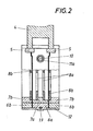
- the drive 9 for the milling units 6a, 6b has a drivable ball screw 10, which interacts with two gear nuts 11a, 11b.
- One gear nut 11a is seated in the middle milling unit 6a and the other gear nut 11b is mounted in a bridge 12 which combines the two outer milling units 6b to form a common drive group, so that, according to the two gear nuts 11a, 11b with the drive 9, both the middle one Milling unit 6a and the two outer milling units 6 b can be moved.
- the bridge 12 engages around the middle milling unit 6a on the side facing away from the milling carriage and forms an additional guide 13 opposite the guide 5 of the milling carriage 4, so that the milling units are not only supported on the milling carriage 4, but also mutually.
- Fig. 1 to 3 10 has the ball screw for the two rotationally fixed in the milling unit 6a or in the bridge 12 mounted gear nuts 11a, 11b, two threaded sections 14a, 14b of opposite thread direction, whereby rotation of the spindle 10 is an equal and opposite movement the gear nuts and thus the middle milling unit 6 a .
- the two outer Milling units 6b on the other hand.
- the cutter heads 8a, 8b can plunge independently of one another regardless of the stroke position of the crank pins and execute their circular feed in opposite directions for machining the pin, so that, for example, a simultaneous machining of all crank pins and all cheek side surfaces of a four-stroke Crankshaft is possible with the shortest milling times (Fig. 3).
- the plunge movement is carried out solely by the drive 9 for the milling units and the movement for the circular feed takes place through a corresponding coordination between drive 9 and spindle drive 3 for the milling slide 4, so that the desired round feed is created by the combination of the movement components lying in the displacement directions .
- the ball screw 10 for the gear nuts 11a, 11b has threaded sections 15a, 15b of the same pitch direction, so that the gear nuts and thus the milling units 6a 6b are moved in the same direction when the spindle rotates.
- the gear nut 11b is rotatably mounted in the bridge 12 and can be blocked by a brake 16.
- This brake 16 has two between them a brake flange 17 of the gear nut 11b receiving brake shoes 18, 19, which are mutually displaceable and by brake springs 20 in the brake are sensibly burdened.
- a brake springs 20'entumble memorider hydraulic drive 21 of from respective piston and cylinder parts 18a, 19a of the brake shoes 18, 1 9 is formed by pressurizing allows a release of the brake. If the brake is released, the gear nut 11b can take part in the spindle rotation, so that only the gear nut 11a is moved axially and a relative adjustment takes place between the milling unit 6a and the bridge 12 or the milling units 6b. In order to carry out this adjustment process exactly, a clamping device 22 is provided which clamps the milling units 6b on the milling slide 4.
- the brake 16 is reactivated and the clamping device 22 is opened so that the milling units 6a, 6b in the given relative position plunge in the same direction and can be subjected to a round feed (FIG. 6). Since the milling units here do not perform any relative movement during milling, the milling units 13a, 13b can be clamped together by a clamping device 23, which brings about a stabilization of the tool guide.
Landscapes
- Engineering & Computer Science (AREA)
- Mechanical Engineering (AREA)
- Milling Processes (AREA)
- Gear Processing (AREA)
Priority Applications (3)
| Application Number | Priority Date | Filing Date | Title |
|---|---|---|---|
| DE8585890015T DE3565373D1 (en) | 1985-01-22 | 1985-01-22 | Milling machine for working crank shafts, etc. |
| EP19850890015 EP0189018B1 (fr) | 1985-01-22 | 1985-01-22 | Fraiseuse à usiner des vilebrequins ou similaires |
| JP619686A JPS61188013A (ja) | 1985-01-22 | 1986-01-14 | クランク軸など加工用のフライス盤 |
Applications Claiming Priority (1)
| Application Number | Priority Date | Filing Date | Title |
|---|---|---|---|
| EP19850890015 EP0189018B1 (fr) | 1985-01-22 | 1985-01-22 | Fraiseuse à usiner des vilebrequins ou similaires |
Publications (2)
| Publication Number | Publication Date |
|---|---|
| EP0189018A1 true EP0189018A1 (fr) | 1986-07-30 |
| EP0189018B1 EP0189018B1 (fr) | 1988-10-05 |
Family
ID=8194744
Family Applications (1)
| Application Number | Title | Priority Date | Filing Date |
|---|---|---|---|
| EP19850890015 Expired EP0189018B1 (fr) | 1985-01-22 | 1985-01-22 | Fraiseuse à usiner des vilebrequins ou similaires |
Country Status (3)
| Country | Link |
|---|---|
| EP (1) | EP0189018B1 (fr) |
| JP (1) | JPS61188013A (fr) |
| DE (1) | DE3565373D1 (fr) |
Cited By (5)
| Publication number | Priority date | Publication date | Assignee | Title |
|---|---|---|---|---|
| DE3638698A1 (de) * | 1986-11-13 | 1988-05-19 | Siemens Ag | Einrichtung zur linearen bewegung eines maschinenteils bei einer numerisch gesteuerten werkzeugmaschine |
| FR2815896A1 (fr) * | 2000-10-31 | 2002-05-03 | Hsi Kuan Chen | Centre d'usinage a commande numerique |
| ES2212867A1 (es) * | 2000-11-10 | 2004-08-01 | Hsi-Kuan Chen | Centro de maquinado de cno con caracteristica de desplazamiento a doble velocidad en los ejes x e y. |
| CN103084850A (zh) * | 2013-01-16 | 2013-05-08 | 苏州爱博纳重工装备科技有限公司 | 数控曲柄车铣床中的t形滑枕与门式主机体 |
| CN113877864A (zh) * | 2021-09-03 | 2022-01-04 | 安徽长中刷业有限公司 | 一种刷辊连接件及其铣削装置 |
Citations (8)
| Publication number | Priority date | Publication date | Assignee | Title |
|---|---|---|---|---|
| US2232304A (en) * | 1938-03-30 | 1941-02-18 | Jefferson Union Company | Machine tool |
| GB582037A (en) * | 1944-07-10 | 1946-11-01 | Butler Machine Tool Company Lt | Improvements relating to screw traversing mechanism |
| US3387517A (en) * | 1965-12-21 | 1968-06-11 | Madison Ind Inc | Toolhead |
| FR2267848A1 (en) * | 1974-04-19 | 1975-11-14 | Cri Dan | Numerically controlled screw cutting slide lathe - has two drive screws with selective blocked guide nuts |
| DE2559824B1 (de) * | 1975-11-14 | 1978-08-03 | Boehringer Gmbh Geb | Werkzeugmaschine zum Bearbeiten der Zapfen einer Kurbelwelle |
| GB2045138A (en) * | 1979-03-08 | 1980-10-29 | Gfm Fertigungstechnik | Crankshaft milling |
| GB2094930A (en) * | 1981-03-13 | 1982-09-22 | Teramachi Hiroshi | Ball screw and spline assembly |
| EP0142592A1 (fr) * | 1983-11-15 | 1985-05-29 | GFM Gesellschaft für Fertigungstechnik und Maschinenbau Gesellschaft m.b.H. | Machine de fraisage pour l'usinage de vilebrequins et de pièces analogues |
-
1985
- 1985-01-22 EP EP19850890015 patent/EP0189018B1/fr not_active Expired
- 1985-01-22 DE DE8585890015T patent/DE3565373D1/de not_active Expired
-
1986
- 1986-01-14 JP JP619686A patent/JPS61188013A/ja active Granted
Patent Citations (8)
| Publication number | Priority date | Publication date | Assignee | Title |
|---|---|---|---|---|
| US2232304A (en) * | 1938-03-30 | 1941-02-18 | Jefferson Union Company | Machine tool |
| GB582037A (en) * | 1944-07-10 | 1946-11-01 | Butler Machine Tool Company Lt | Improvements relating to screw traversing mechanism |
| US3387517A (en) * | 1965-12-21 | 1968-06-11 | Madison Ind Inc | Toolhead |
| FR2267848A1 (en) * | 1974-04-19 | 1975-11-14 | Cri Dan | Numerically controlled screw cutting slide lathe - has two drive screws with selective blocked guide nuts |
| DE2559824B1 (de) * | 1975-11-14 | 1978-08-03 | Boehringer Gmbh Geb | Werkzeugmaschine zum Bearbeiten der Zapfen einer Kurbelwelle |
| GB2045138A (en) * | 1979-03-08 | 1980-10-29 | Gfm Fertigungstechnik | Crankshaft milling |
| GB2094930A (en) * | 1981-03-13 | 1982-09-22 | Teramachi Hiroshi | Ball screw and spline assembly |
| EP0142592A1 (fr) * | 1983-11-15 | 1985-05-29 | GFM Gesellschaft für Fertigungstechnik und Maschinenbau Gesellschaft m.b.H. | Machine de fraisage pour l'usinage de vilebrequins et de pièces analogues |
Cited By (6)
| Publication number | Priority date | Publication date | Assignee | Title |
|---|---|---|---|---|
| DE3638698A1 (de) * | 1986-11-13 | 1988-05-19 | Siemens Ag | Einrichtung zur linearen bewegung eines maschinenteils bei einer numerisch gesteuerten werkzeugmaschine |
| FR2815896A1 (fr) * | 2000-10-31 | 2002-05-03 | Hsi Kuan Chen | Centre d'usinage a commande numerique |
| ES2212867A1 (es) * | 2000-11-10 | 2004-08-01 | Hsi-Kuan Chen | Centro de maquinado de cno con caracteristica de desplazamiento a doble velocidad en los ejes x e y. |
| CN103084850A (zh) * | 2013-01-16 | 2013-05-08 | 苏州爱博纳重工装备科技有限公司 | 数控曲柄车铣床中的t形滑枕与门式主机体 |
| CN113877864A (zh) * | 2021-09-03 | 2022-01-04 | 安徽长中刷业有限公司 | 一种刷辊连接件及其铣削装置 |
| CN113877864B (zh) * | 2021-09-03 | 2023-04-07 | 安徽长中刷业有限公司 | 一种刷辊连接件及其铣削装置 |
Also Published As
| Publication number | Publication date |
|---|---|
| DE3565373D1 (en) | 1988-11-10 |
| EP0189018B1 (fr) | 1988-10-05 |
| JPS61188013A (ja) | 1986-08-21 |
| JPH028843B2 (fr) | 1990-02-27 |
Similar Documents
| Publication | Publication Date | Title |
|---|---|---|
| DE3035451C2 (fr) | ||
| DE3624284C2 (de) | Bearbeitungsmaschine mit einem auf einer Wiege angeordneten, rotierbar gelagerten Tisch | |
| DE102009048416B3 (de) | Verzahnungsschleifmaschine | |
| CH629407A5 (de) | Werkzeugmaschine. | |
| EP0249742B1 (fr) | Machine de propulsion centrale | |
| DE3241844C1 (de) | Stanzmaschine mit Revolvertrommel | |
| DE3320940A1 (de) | Zweispindeldrehmaschine | |
| DE1627042B2 (de) | Vorrichtung mit einem indexierbaren werkstuecktraeger und mit einem diesen foerdernden foerderring an einer ringtransfermaschine | |
| DE976248C (de) | Fraesmaschine | |
| EP0189018B1 (fr) | Fraiseuse à usiner des vilebrequins ou similaires | |
| DE2636986C3 (de) | Drehmaschine | |
| EP0227663B1 (fr) | Appareil d'usinage pour endenter les roues dentees | |
| EP0142592B1 (fr) | Machine de fraisage pour l'usinage de vilebrequins et de pièces analogues | |
| EP0379723B1 (fr) | Tour à usiner des gorges équipé d'outils | |
| DE3211170A1 (de) | Kopierfraes-, kopierschleif- bzw. kopier-bohrmaschine | |
| DE19504370A1 (de) | Mehrspindeldrehmaschine | |
| DE3933863A1 (de) | Schleifmaschine | |
| DE1966960B2 (de) | Wälzfräseinrichtung als Zusatzgerät für Drehautomaten | |
| DE1271501B (de) | Mehrspindel-Drehautomat | |
| DE2940659C2 (fr) | ||
| DE3518287C2 (fr) | ||
| EP0167112A1 (fr) | Procédé et appareil pour fraiser et rainurer des parties d'un cadre en bois | |
| DE6915106U (de) | Vorrichtung zum spanlosen bearbeiten von zahnraedern | |
| DE2953199C2 (de) | Kurbelwellenfräsmaschine | |
| EP0260477B1 (fr) | Machine à brochage verticale |
Legal Events
| Date | Code | Title | Description |
|---|---|---|---|
| PUAI | Public reference made under article 153(3) epc to a published international application that has entered the european phase |
Free format text: ORIGINAL CODE: 0009012 |
|
| AK | Designated contracting states |
Kind code of ref document: A1 Designated state(s): DE FR GB IT |
|
| 17P | Request for examination filed |
Effective date: 19860731 |
|
| 17Q | First examination report despatched |
Effective date: 19870821 |
|
| GRAA | (expected) grant |
Free format text: ORIGINAL CODE: 0009210 |
|
| AK | Designated contracting states |
Kind code of ref document: B1 Designated state(s): DE FR GB IT |
|
| ITF | It: translation for a ep patent filed | ||
| REF | Corresponds to: |
Ref document number: 3565373 Country of ref document: DE Date of ref document: 19881110 |
|
| GBT | Gb: translation of ep patent filed (gb section 77(6)(a)/1977) | ||
| ET | Fr: translation filed | ||
| PLBE | No opposition filed within time limit |
Free format text: ORIGINAL CODE: 0009261 |
|
| STAA | Information on the status of an ep patent application or granted ep patent |
Free format text: STATUS: NO OPPOSITION FILED WITHIN TIME LIMIT |
|
| 26N | No opposition filed | ||
| PGFP | Annual fee paid to national office [announced via postgrant information from national office to epo] |
Ref country code: FR Payment date: 19901228 Year of fee payment: 7 |
|
| PGFP | Annual fee paid to national office [announced via postgrant information from national office to epo] |
Ref country code: GB Payment date: 19910110 Year of fee payment: 7 |
|
| ITTA | It: last paid annual fee | ||
| PG25 | Lapsed in a contracting state [announced via postgrant information from national office to epo] |
Ref country code: GB Effective date: 19920122 |
|
| REG | Reference to a national code |
Ref country code: GB Ref legal event code: PCNP |
|
| PG25 | Lapsed in a contracting state [announced via postgrant information from national office to epo] |
Ref country code: FR Effective date: 19920930 |
|
| REG | Reference to a national code |
Ref country code: FR Ref legal event code: ST |
|
| PGFP | Annual fee paid to national office [announced via postgrant information from national office to epo] |
Ref country code: DE Payment date: 19940128 Year of fee payment: 10 |
|
| PG25 | Lapsed in a contracting state [announced via postgrant information from national office to epo] |
Ref country code: DE Effective date: 19951003 |