EP0189038A2 - Sauerstoffsensor - Google Patents
Sauerstoffsensor Download PDFInfo
- Publication number
- EP0189038A2 EP0189038A2 EP86100067A EP86100067A EP0189038A2 EP 0189038 A2 EP0189038 A2 EP 0189038A2 EP 86100067 A EP86100067 A EP 86100067A EP 86100067 A EP86100067 A EP 86100067A EP 0189038 A2 EP0189038 A2 EP 0189038A2
- Authority
- EP
- European Patent Office
- Prior art keywords
- cell
- heater
- solid
- electrolyte body
- oxygen sensor
- Prior art date
- Legal status (The legal status is an assumption and is not a legal conclusion. Google has not performed a legal analysis and makes no representation as to the accuracy of the status listed.)
- Granted
Links
Images


Classifications
-
- G—PHYSICS
- G01—MEASURING; TESTING
- G01N—INVESTIGATING OR ANALYSING MATERIALS BY DETERMINING THEIR CHEMICAL OR PHYSICAL PROPERTIES
- G01N27/00—Investigating or analysing materials by the use of electric, electrochemical, or magnetic means
- G01N27/26—Investigating or analysing materials by the use of electric, electrochemical, or magnetic means by investigating electrochemical variables; by using electrolysis or electrophoresis
- G01N27/416—Systems
-
- G—PHYSICS
- G01—MEASURING; TESTING
- G01N—INVESTIGATING OR ANALYSING MATERIALS BY DETERMINING THEIR CHEMICAL OR PHYSICAL PROPERTIES
- G01N27/00—Investigating or analysing materials by the use of electric, electrochemical, or magnetic means
- G01N27/26—Investigating or analysing materials by the use of electric, electrochemical, or magnetic means by investigating electrochemical variables; by using electrolysis or electrophoresis
- G01N27/403—Cells and electrode assemblies
- G01N27/406—Cells and probes with solid electrolytes
- G01N27/407—Cells and probes with solid electrolytes for investigating or analysing gases
- G01N27/4071—Cells and probes with solid electrolytes for investigating or analysing gases using sensor elements of laminated structure
-
- G—PHYSICS
- G01—MEASURING; TESTING
- G01N—INVESTIGATING OR ANALYSING MATERIALS BY DETERMINING THEIR CHEMICAL OR PHYSICAL PROPERTIES
- G01N27/00—Investigating or analysing materials by the use of electric, electrochemical, or magnetic means
- G01N27/26—Investigating or analysing materials by the use of electric, electrochemical, or magnetic means by investigating electrochemical variables; by using electrolysis or electrophoresis
- G01N27/403—Cells and electrode assemblies
- G01N27/406—Cells and probes with solid electrolytes
- G01N27/4067—Means for heating or controlling the temperature of the solid electrolyte
Definitions
- the present invention relates to an oxygen sensor, and particularly to an oxygen sensor suited for measuring the concentration of an oxygen gas contained in an exhaust gas of an automobile.
- An oxygen sensor of this kind has a heater attached to a cell, and as for its manufacturing technique, the following methods are proposed, one of which is described in Japanese Utility Model Laid-Open No. 130,261/1983 in which green sheets of ZrO 2 and Al 2 O 3 as cell elements and an electric insulating substrate, respectively are formed, electrodes, heaters, etc. are printed on the green sheets, and they are laminated and then sintered simultaneously without using a bonding agent.
- the other method is disclosed in Japanese Patent Laid-Open No.
- An object of the present invention is to provide an oxygen sensor constructed of a cell and a heater which are formed of ceramic materials having different thermal expansion coefficients and which are joined to each other so that a joint portion is proof against a heat cycle and a thermal shock and allows the heater to heat the cell with excellent heat conduction.
- the present invention is characterized in that: in view that a ceramic material sometimes shows a nonlinear displacement of considerable hysteresis due to phase transition in relation to thermal behavior, a cell and a heater formed of ceramic materials having different thermal expansion coefficients are joined to each other with an intermediate layer interposed between the cell and the heater and absorbing or buffering the amount of displacement of the joint interface between the cell and the heater.
- the heater structural member is so formed that the cell is surrounded by and embedded in the heater, thereby to increase the durability of the joining strength, and the intermediate layer is interposed between the cell and the heater so that the cell is brought into a close contact with the structural member of the heater during a period when they are under heating and that the cell is held in the heater to be prevented from dropping out during a period when they are not heated.
- the cell In order to stabilize the temperature of the cell so that the cell retain a required accuracy in detection in the condition that the seneor is exposed to a gas to be inspected which shows frequent fluctuation in temperature, the cell is surrounded by the structural member of the heter except for the portion of the detection electrode thereof, while a porous protective film may be provided on the detecting portion of the cell. It is preferable to use a means to impart negative feedback control on the heating power of the heater based on an electric signal representing the temperature of the cell.
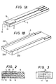
- the oxygen sensor comprises a cell 1, a heater 3 and an intermediate layer (not shown in Figs. 1A,1B and will be described later) attaching the cell 1 to the heater 3.
- the cell 1 consist of two cell parts which are superposed each other as shown in Figs. 2 and 3. One outputs a signal proportional to the concentration of oxygen, while the other shows a switching output characteristic at an oxygen concentration point corresponding to the theoretical air-fuel ratio point. The cell 1 is described referring to Figs. 2 and 3.
- a solid-electrolyte body 5 of Y 2 0 3 -stabilized Zr0 2 consists of three layers which are joined to be one piece, and has two chambers 7, 9 which are formed in parallel with each other and extend along the length direction of the solid-electrolyte body 5.
- the chamber 7 has a narrow slit-like opening 11 at one end of the cell 1 while the chamber 9 has a relatively wide slit-like opening 13 at the same end as the above opening 11.
- a pair of porous electrodes 15 and 17 are formed opposite to each other so as to sandwitch a part of the solid-electrolyte body 5.
- the electrode 15 is mounted on the upper surface of the solid-electrolyte body 5, and the electrode 17 is joined to the surface of a wall part defining the chamber 7.
- another porous electrode 19 is provided which is made in a pair with the electrode 15.
- the electrodes 15, 17 and 19 have a power of adsorbing and dissociating an oxygen gas (0 2 ) and formed of platinum, for instance.
- the electrode 15 is called a detection electrode which is exposed to a gas to be inspected and dissociates into the gas the oxygen ions coming from the opposite electrode 19.
- This electrode 19 is called a reference electrode, which has a'number of fine openings and is exposed into a space formed around the electrode and partitioned from the surrounding gas to be inspected, that is, a diffusion chamber 9.
- This diffusion chamber 9 and the gas to be inspected communicate with each other through the opening 13 for diffusion.
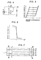
- a current Ip is made to flow from the detection electrode 15 to the reference electrode 19 as shown in Fig. 4 while the temperature of the solid-electrolyte body 5 is 600 to 800°C
- the oxygen in the diffusion chamber 9 is adsorbed to and ionized by the reference electrode 19, and the oxygen ions thus formed are pumped out through the solid-electrolyte body 5.
- the concentration of the oxygen on the reference electrode 19 side turns constantly smaller than that on the detection electrode 15, and thus an electromotive force of a concentration cell is induced.
- An induced electromotive force 1 V, for instance, can be obtained, according to Nernst's equation, when the temperature of the solid-electrolyte body 5 is 700°C and when the oxygen concentration ratio between the detection electrode 15 and the reference electrode 19 is of 20 figures. Since the oxygen in the gas to be inspected is regulated in speed selectively in the diffusion opening 13 when it is diffused into the diffusion chamber 9, all of it is pumped out sequentially; consequently, the current thus induced shows a corresponding threshold value when the concentration P 0 of the oxygen in the gas to be inspected is constant.
- the proportional relationship between the concentration P 0 of the oxygen in the gas to be inspected and Ip is established by applying a feedback to the current Ip by an electronic circuit so that the induced electromotive force E between the detection electrode 15 and the reference electrode 19 may take a prescribed value, for instance.
- Fig. 5 shows this relationship.
- the cell part of the opposite electrodes 15-17 has a different usage from that of the above-mentioned cell part.
- the cell part is an oxygen concentration cell, in which oxygen is pumped constantly from the detection electrode 15 into the chamber 7 surrounding the reference electrode 17 for reserving the oxygen, an excess oxygen escapes out of the chamber 7 through the opening 11, and thus the concentration thereof is maintained virtually at a value approximating the concentration of oxygen in the atmosphere. Based on this value as a reference, the concentration of the oxygen around the detection electrode 15 is measured according to Nernst's equation on the concentration cell.
- the output characteristic in this case is that: when platinum is used for the detection electrode 15, the catalytic function thereof makes the concentration of oxygen around the detection electrode 15 smaller by about 20 figures than that around the reference electrode 17 in a region in which fuel is more concentrated than the one at a theoretical air-fuel ratio point.
- Figure 6 which shows the output characteristic of the cell of 0 2 sensor for an automobile showing the theoretical air-fuel ratio point.
- the cell 1 including the two cell parts superposed in layers are joined to the heater 3.
- the cell 1 is joined to the heater 3 so that the cell part outputting a proportional signal is opposed to the heater 3, thereby both the cell parts can be improved in the temperature dependence.
- Fig. 7 shows a plane view of the oxygen sensor in which the cell 1 formed in plate and elongated in embeded in the heater 3.
- the cell is provided with the chambers 7, 9 and various electrodes 15, 17, 19 at one end portion, and various terminals at the other end.
- the cell 1 is provided, at one end, with the electrodes 15, 17 and 19 as mentioned above, and, at the other end, with terminals 151, 171 and 191 which are electrically connected to the electrodes 15, 17 and 19, respectively.
- the reference electrode 17 is disposed in the reserving chamber 7 with the opening 11 and has a lead portion 172 which is electrically connected to the terminal 171 through a lead 173 inserted in a through hole formed in the solid-electrolyte body 5.
- the reference electrode 19 is disposed in the diffusion chamber 9 with the opening 13 and has a lead portion 192 which is electrically connected to the terminal 191 through a lead 193 inserted in a through hole made in the solid-electrolyte body 5 as shown in Figs. 9 and 11.
- the heater 3 comprises an electrically insulating substrate 23 and a heating element 25 embeded in the substrate 23.
- the substrate 23 is made of Ak 2 0 3 as a principal component, that is, Ak 2 0 3 -base ceramics and tungsten oxide and its plate-like shape are preferable for the heating element 25.
- the heating element 25 is arranged in a zigzag shape around the chambers 7, 9. Both the ends 252 of the heating element 25 are electrically connected to the terminals 251 through leads 253 inserted in through holes made in the substrate 23.
- the substrate 23, which is made in plate, has a recess 230 of a substantially rectangular cross section, which is elongated in its length direction, as best shown in Fig. 1B.
- the recess 230 makes a pair of side wall portions 232 at both the sides of the recess 230 so as to project from a bottom surface 231, thereby providing a U-shaped cross section.
- An adhesive is disposed on the surface of the recess 230 of the substrate 23 which is sintered beforehand at 1600°C for example, the cell, which also is sintered beforehand at 1500°C, for example, is disposed on the adhesive, and then the laminated cell 1 and the heater 3 are baked to a temperature lower than a sintering temperature of the substrate 23, for example 1100-1200°C, thereby forming an intermediate layer 21 between the cell 1 and the heater 3.
- the intermediate layer.21 is not completely sintered, has a number of fine cracks of the order of ⁇ m, and presents an unglazed-like porcelain state.
- the thickness of the intermediate layer 21 is about 0.05 mm between the side wall portions 232 and about 0.2 mm at the side wall portions 232.
- the thickness of the substrate 23 is about the same as the thickness of the cell 1.
- the thickness of the side wall portions 232 is about 1.5 times as thick as the cell 1 or thicker than the cell 1.
- the depth of the recess 230 is about 1/2 times the thickness of the cell 1 so that the diffusion chamber 9 for wide range fuel-air ratio signal generation cell part is completely embeded by the side wall portions 232 and the bottom surface 231 of the substrate 23 of the heater 3, except for the end surface provided with the diffusion chamber opening 13.
- thus formed oxygen sensor has adhesion strength of about three times or higher adhesive strength at the abutment between the cell 1 and the heater 3 as compared with an oxygen sensor in which a cell is joined to a heater without such side wall portions as mentioned above.
- both the cell 1 and the heater 3 expand, and since the solid-electrolyte body 5 of Y 2 0 3 -stabilized ZrO 2 is larger in thermal expansion coefficient than the substrate 23 of AL203.
- the cell 1 presses the intermediate layer 21 with cracks on the side wall portions 232, so that the cell 1 and the heater 3 are brought into a tight or close contact, with the cracks of the intermediate layer 21 being tightly closed.
- the intermediate layer 21 on the bottom surface 231 of the recess 230 also is pressed by the cell 1 and the heater 3 due to expansion of them, therefore, the cell 1 is brought into a tight or close contact with the heater 3 at the bottom surface 231 of the recess 230, as a whole the cell 1 is brought into a tight contact with the heater 3.
- the intermediate layer 21 restors the original states of cracks. This behavior of this intermediate layer 21 enables it to absorb stresses caused by thermal shock received by the oxygen sensor.
- the cell 1 is formed mainly of Y 2 0 3 - stabilized Zr0 2
- the heater is formed mainly of Al 2 O 3
- these are sintered beforehand respectively.
- a compound containing Al 2 O 3 as a main agent, and ZrO 2 , SiO, MgO or the like is used as an aid to bonding or sintering them.
- an aqueous 1 liquid type paste-like bonding agent formed of 95% Al 2 O 3 , 4% Zr0 2 and 1% SiO is used.
- a compound other than the above which includes 50-95% Al 2 O 3 , 50-4% Zr0 2 and at least one of SiO and MgO as the remaining also can be used for joining the heater 3 to the cell 1.
- the heater 3 and the cell 1 are sintered in appropriate sintering processes respectively, and then they may be bonded thereafter by a bonding agent containing Al 2 O 3 as its main agent, ZrO 2 , SiO or MgO as an bonding aid.
- the cell 1 is composed of the theoretical air-fuel ratio point detection cell part and the wide-range air-fuel ratio function signal generating cell part, and the latter is so disposed that it may closely contact the u-shaped section of the heater 3, while the former is so disposed that it may be superposed in a layer on the latter.
- the heater 3 is joined directly to the cell part outputting a fuel-air ratio proportional signal; thereby the heat controllability is improved and both cell parts can be improved in the temperature dependence.
- Figs. 13A and 13B show a cell 30 and a heater 31 which are provided with cavities 41 to 44, and 51 to 54, respectively.
- the cavities are filled with the substance of the intermediate layer or the bonding agent, so that a wedging effect is produced.
- the temperature on the surface of the cell 1 lowers with an increase in the speed of a gas flow, which is indicated by a characteristic curve B, while the temperature between the cell 1 and the heater 3 is maintained virtually at a fixed level, which is indicated by a characteristic curve A.
- the cell is provided with recesses, an inclination, a etaged portion or others in the direction of the thickness thereof so that the form of the bonding agent may have wedging effect for the cell after it is set, and that the heater is also provided with such recesses, an inclination, a staged portion or others as aforesaid on both sides of the u-shaped section thereof.
Landscapes
- Chemical & Material Sciences (AREA)
- Life Sciences & Earth Sciences (AREA)
- Health & Medical Sciences (AREA)
- Physics & Mathematics (AREA)
- Chemical Kinetics & Catalysis (AREA)
- Electrochemistry (AREA)
- Molecular Biology (AREA)
- Analytical Chemistry (AREA)
- Biochemistry (AREA)
- General Health & Medical Sciences (AREA)
- General Physics & Mathematics (AREA)
- Immunology (AREA)
- Pathology (AREA)
- Measuring Oxygen Concentration In Cells (AREA)
Applications Claiming Priority (2)
| Application Number | Priority Date | Filing Date | Title |
|---|---|---|---|
| JP60010899A JPH0646189B2 (ja) | 1985-01-25 | 1985-01-25 | 酸素濃度センサ |
| JP10899/85 | 1985-01-25 |
Publications (3)
| Publication Number | Publication Date |
|---|---|
| EP0189038A2 true EP0189038A2 (de) | 1986-07-30 |
| EP0189038A3 EP0189038A3 (en) | 1987-01-07 |
| EP0189038B1 EP0189038B1 (de) | 1989-09-20 |
Family
ID=11763143
Family Applications (1)
| Application Number | Title | Priority Date | Filing Date |
|---|---|---|---|
| EP86100067A Expired EP0189038B1 (de) | 1985-01-25 | 1986-01-03 | Sauerstoffsensor |
Country Status (7)
| Country | Link |
|---|---|
| US (1) | US4650560A (de) |
| EP (1) | EP0189038B1 (de) |
| JP (1) | JPH0646189B2 (de) |
| KR (1) | KR890001983B1 (de) |
| CN (1) | CN86100466B (de) |
| CA (1) | CA1227539A (de) |
| DE (1) | DE3665773D1 (de) |
Cited By (8)
| Publication number | Priority date | Publication date | Assignee | Title |
|---|---|---|---|---|
| EP0281378A3 (en) * | 1987-03-03 | 1989-11-29 | Ngk Insulators, Ltd. | Electrochemical device having a heater |
| EP0480076A1 (de) * | 1990-09-13 | 1992-04-15 | Honeywell B.V. | Verfahren und Messfühler zur Bestimmung von Sauerstoffpartialdruck |
| WO1995016199A1 (de) * | 1993-12-09 | 1995-06-15 | Robert Bosch Gmbh | Isolationsschichtsystem zur galvanischen trennung von stromkreisen |
| WO1996012947A1 (de) * | 1994-10-20 | 1996-05-02 | Robert Bosch Gmbh | Sensorelement |
| WO1996024051A1 (de) * | 1995-02-02 | 1996-08-08 | Robert Bosch Gmbh | Keramische schichtsysteme, insbesondere für gassensoren |
| EP0667523A3 (de) * | 1994-02-15 | 1996-09-11 | Gen Motors Corp | Abgassensor mit einer Kompositfliese als Fühlerelement und Herstellungsverfahren. |
| US5773894A (en) * | 1993-12-09 | 1998-06-30 | Robert Bosch Gmbh | Insulation layer system for the electrical isolation circuits |
| WO2013034352A1 (de) * | 2011-09-06 | 2013-03-14 | Robert Bosch Gmbh | Verfahren zum herstellen eines sensorelements |
Families Citing this family (24)
| Publication number | Priority date | Publication date | Assignee | Title |
|---|---|---|---|---|
| US4744954A (en) * | 1986-07-11 | 1988-05-17 | Allied-Signal Inc. | Amperometric gas sensor containing a solid electrolyte |
| JPH087179B2 (ja) * | 1986-09-27 | 1996-01-29 | 日本碍子株式会社 | ガスセンサ |
| JPS6388244A (ja) * | 1986-09-30 | 1988-04-19 | Mitsubishi Electric Corp | 空燃比制御装置 |
| US4753204A (en) * | 1986-09-30 | 1988-06-28 | Mitsubishi Denki Kabushiki Kaisha | Air-fuel ratio control system for internal combustion engines |
| US4861459A (en) * | 1987-01-16 | 1989-08-29 | Uop Inc. | Low pressure mixing process for atomizing fluids |
| US4880519A (en) * | 1988-05-24 | 1989-11-14 | Gte Laboratories Incorporated | Gas sensor element |
| US4897174A (en) * | 1988-05-24 | 1990-01-30 | Gte Laboratories Incorporated | Gas sensing apparatus |
| US5827415A (en) * | 1994-09-26 | 1998-10-27 | The Board Of Trustees Of Leland Stanford Jun. Univ. | Oxygen sensor |
| JP3686272B2 (ja) * | 1998-12-21 | 2005-08-24 | 株式会社日立製作所 | 空燃比センサ及びこれを用いたエンジン燃焼制御システム |
| DE60037471T2 (de) * | 1999-02-03 | 2008-12-04 | NGK Spark Plug Co., Ltd., Nagoya-shi | Festelektrolyt mit isolierenden keramischen Körnern für Gassensoren, und Methode zu dessen Herstellung |
| JP4453166B2 (ja) * | 2000-06-19 | 2010-04-21 | 株式会社デンソー | 積層型ガスセンサ素子及びその製造方法 |
| JP2002228626A (ja) | 2000-11-30 | 2002-08-14 | Denso Corp | ガスセンサ素子 |
| GB2387230B (en) * | 2002-02-28 | 2005-12-21 | Ngk Spark Plug Co | Prismatic ceramic heater for heating gas sensor element, prismatic gas sensor element in multi-layered structure including the prismatic ceramic heater, |
| DE10225149A1 (de) * | 2002-06-06 | 2004-01-15 | Robert Bosch Gmbh | Sensorelement |
| WO2004109252A2 (en) * | 2003-05-30 | 2004-12-16 | University Of Southern California | Oxygen sensor with a solid state reference and manufacturing thereof |
| JP4407373B2 (ja) * | 2004-05-13 | 2010-02-03 | 株式会社デンソー | ガスセンサ素子 |
| JP4430591B2 (ja) * | 2005-07-25 | 2010-03-10 | 日本特殊陶業株式会社 | ガスセンサ素子及びガスセンサ |
| JP4783095B2 (ja) * | 2005-09-06 | 2011-09-28 | 新コスモス電機株式会社 | 水素ガス検出素子および水素ガス検出装置 |
| US8168053B2 (en) * | 2006-01-23 | 2012-05-01 | Denso Corporation | Gas sensing member used for gas sensor and method of manufacturing the member |
| CN102721729B (zh) * | 2011-10-12 | 2014-06-25 | 宁波大学 | 一种采用8YSZ和Al2O3材质叠层制备的极限电流型氧传感器 |
| JP5829159B2 (ja) * | 2012-03-16 | 2015-12-09 | 株式会社デンソー | ガスセンサ素子及びその製造方法 |
| WO2014170939A1 (ja) | 2013-04-15 | 2014-10-23 | 三菱電機株式会社 | 回転機械の回転子 |
| CN110749638B (zh) * | 2019-09-23 | 2024-04-09 | 中国航空工业集团公司上海航空测控技术研究所 | 一种基于氧化锆的微型氧浓度传感元件 |
| JP7294178B2 (ja) | 2020-02-17 | 2023-06-20 | 株式会社デンソー | ガスセンサ素子 |
Family Cites Families (10)
| Publication number | Priority date | Publication date | Assignee | Title |
|---|---|---|---|---|
| DE2909452C2 (de) * | 1979-03-10 | 1986-12-18 | Robert Bosch Gmbh, 7000 Stuttgart | Elektrochemischer Meßfühler für die Bestimmung des Sauerstoffgehaltes in Gasen, insbesondere in Abgasen |
| JPS55154451A (en) * | 1979-05-19 | 1980-12-02 | Nissan Motor Co Ltd | Production of substrate for gas sensor |
| JPS57147049A (en) * | 1981-03-06 | 1982-09-10 | Nissan Motor Co Ltd | Oxygen sensor element |
| JPS57211543A (en) * | 1981-06-23 | 1982-12-25 | Nissan Motor Co Ltd | Electric current control device for oxygen sensor |
| JPS58130261A (ja) * | 1982-01-28 | 1983-08-03 | Matsushita Electric Ind Co Ltd | マンガン−アルミニウム−炭素系合金磁石の製造法 |
| JPS5991357A (ja) * | 1982-11-17 | 1984-05-26 | Ngk Spark Plug Co Ltd | ヒ−タ付酸素センサ |
| JPS6036948A (ja) * | 1983-08-09 | 1985-02-26 | Ngk Insulators Ltd | 電気化学的装置 |
| US4579643A (en) * | 1983-11-18 | 1986-04-01 | Ngk Insulators, Ltd. | Electrochemical device |
| JPS60219547A (ja) * | 1984-04-16 | 1985-11-02 | Nissan Motor Co Ltd | 酸素濃度検出装置 |
| JP2502961B2 (ja) * | 1984-04-26 | 1996-05-29 | 日本碍子株式会社 | 電気化学的装置の製造方法 |
-
1985
- 1985-01-25 JP JP60010899A patent/JPH0646189B2/ja not_active Expired - Lifetime
-
1986
- 1986-01-03 EP EP86100067A patent/EP0189038B1/de not_active Expired
- 1986-01-03 DE DE8686100067T patent/DE3665773D1/de not_active Expired
- 1986-01-07 US US06/816,840 patent/US4650560A/en not_active Expired - Lifetime
- 1986-01-21 CN CN86100466A patent/CN86100466B/zh not_active Expired
- 1986-01-21 CA CA000500035A patent/CA1227539A/en not_active Expired
- 1986-01-24 KR KR1019860000453A patent/KR890001983B1/ko not_active Expired
Cited By (8)
| Publication number | Priority date | Publication date | Assignee | Title |
|---|---|---|---|---|
| EP0281378A3 (en) * | 1987-03-03 | 1989-11-29 | Ngk Insulators, Ltd. | Electrochemical device having a heater |
| EP0480076A1 (de) * | 1990-09-13 | 1992-04-15 | Honeywell B.V. | Verfahren und Messfühler zur Bestimmung von Sauerstoffpartialdruck |
| WO1995016199A1 (de) * | 1993-12-09 | 1995-06-15 | Robert Bosch Gmbh | Isolationsschichtsystem zur galvanischen trennung von stromkreisen |
| US5773894A (en) * | 1993-12-09 | 1998-06-30 | Robert Bosch Gmbh | Insulation layer system for the electrical isolation circuits |
| EP0667523A3 (de) * | 1994-02-15 | 1996-09-11 | Gen Motors Corp | Abgassensor mit einer Kompositfliese als Fühlerelement und Herstellungsverfahren. |
| WO1996012947A1 (de) * | 1994-10-20 | 1996-05-02 | Robert Bosch Gmbh | Sensorelement |
| WO1996024051A1 (de) * | 1995-02-02 | 1996-08-08 | Robert Bosch Gmbh | Keramische schichtsysteme, insbesondere für gassensoren |
| WO2013034352A1 (de) * | 2011-09-06 | 2013-03-14 | Robert Bosch Gmbh | Verfahren zum herstellen eines sensorelements |
Also Published As
| Publication number | Publication date |
|---|---|
| CN86100466A (zh) | 1986-07-23 |
| EP0189038B1 (de) | 1989-09-20 |
| EP0189038A3 (en) | 1987-01-07 |
| JPH0646189B2 (ja) | 1994-06-15 |
| DE3665773D1 (en) | 1989-10-26 |
| US4650560A (en) | 1987-03-17 |
| CA1227539A (en) | 1987-09-29 |
| KR890001983B1 (ko) | 1989-06-05 |
| JPS61170650A (ja) | 1986-08-01 |
| CN86100466B (zh) | 1988-06-22 |
| KR860006038A (ko) | 1986-08-16 |
Similar Documents
| Publication | Publication Date | Title |
|---|---|---|
| EP0189038B1 (de) | Sauerstoffsensor | |
| EP0144185B1 (de) | Elektrochemische Vorrichtung | |
| EP0142992B1 (de) | Elektrochemische Vorrichtung mit einem Messfühlelement | |
| US4798693A (en) | Method of manufacturing an electrochemical device | |
| US4559126A (en) | Electrochemical device | |
| US5288389A (en) | Oxygen sensor with higher resistance to repeated thermal-shocks and shorter warm-up time | |
| EP0310206A2 (de) | Elektrochemische Vorrichtung | |
| EP0294085B1 (de) | Elektrochemische Elemente | |
| EP0188900A2 (de) | Elektrochemische Vorrichtung | |
| JP2744088B2 (ja) | 空燃比センサ | |
| JPH0473101B2 (de) | ||
| CA1222285A (en) | Apparatus for measuring oxygen concentration and method of producing the apparatus | |
| EP0227257B1 (de) | Elektrochemische Vorrichtung | |
| EP0140295B1 (de) | Verfahren zum Betreiben eines Fühlers für Luftkraftstoff-Verhältnisse | |
| JPH08122287A (ja) | ガス成分の濃度の測定装置および方法 | |
| JPS61134655A (ja) | 酸素センサ素子 | |
| EP0343533B1 (de) | Gasfühlelement | |
| US6964733B1 (en) | Planar sensor element | |
| JPH081426B2 (ja) | 電気化学的装置 | |
| JP4693304B2 (ja) | 酸素センサ | |
| JP2003279531A (ja) | 酸素センサ素子 | |
| JP2003107035A (ja) | 酸素センサ | |
| JP2000221158A (ja) | セラミックヒータ及びこれを用いた酸素センサ | |
| JP2003194762A (ja) | 酸素センサ | |
| JPH0426055B2 (de) |
Legal Events
| Date | Code | Title | Description |
|---|---|---|---|
| PUAI | Public reference made under article 153(3) epc to a published international application that has entered the european phase |
Free format text: ORIGINAL CODE: 0009012 |
|
| 17P | Request for examination filed |
Effective date: 19860103 |
|
| AK | Designated contracting states |
Kind code of ref document: A2 Designated state(s): CH DE FR GB IT LI NL SE |
|
| PUAL | Search report despatched |
Free format text: ORIGINAL CODE: 0009013 |
|
| AK | Designated contracting states |
Kind code of ref document: A3 Designated state(s): CH DE FR GB IT LI NL SE |
|
| 17Q | First examination report despatched |
Effective date: 19890117 |
|
| GRAA | (expected) grant |
Free format text: ORIGINAL CODE: 0009210 |
|
| AK | Designated contracting states |
Kind code of ref document: B1 Designated state(s): DE FR GB IT |
|
| REF | Corresponds to: |
Ref document number: 3665773 Country of ref document: DE Date of ref document: 19891026 |
|
| ET | Fr: translation filed | ||
| ITF | It: translation for a ep patent filed | ||
| PLBE | No opposition filed within time limit |
Free format text: ORIGINAL CODE: 0009261 |
|
| STAA | Information on the status of an ep patent application or granted ep patent |
Free format text: STATUS: NO OPPOSITION FILED WITHIN TIME LIMIT |
|
| 26N | No opposition filed | ||
| ITTA | It: last paid annual fee | ||
| PGFP | Annual fee paid to national office [announced via postgrant information from national office to epo] |
Ref country code: FR Payment date: 19911218 Year of fee payment: 7 |
|
| PG25 | Lapsed in a contracting state [announced via postgrant information from national office to epo] |
Ref country code: FR Effective date: 19930930 |
|
| REG | Reference to a national code |
Ref country code: FR Ref legal event code: ST |
|
| PGFP | Annual fee paid to national office [announced via postgrant information from national office to epo] |
Ref country code: DE Payment date: 20010330 Year of fee payment: 16 |
|
| REG | Reference to a national code |
Ref country code: GB Ref legal event code: IF02 |
|
| PGFP | Annual fee paid to national office [announced via postgrant information from national office to epo] |
Ref country code: GB Payment date: 20020107 Year of fee payment: 17 |
|
| PG25 | Lapsed in a contracting state [announced via postgrant information from national office to epo] |
Ref country code: DE Free format text: LAPSE BECAUSE OF NON-PAYMENT OF DUE FEES Effective date: 20020801 |
|
| PG25 | Lapsed in a contracting state [announced via postgrant information from national office to epo] |
Ref country code: GB Free format text: LAPSE BECAUSE OF NON-PAYMENT OF DUE FEES Effective date: 20030103 |
|
| GBPC | Gb: european patent ceased through non-payment of renewal fee |
Effective date: 20030103 |
|
| PG25 | Lapsed in a contracting state [announced via postgrant information from national office to epo] |
Ref country code: IT Free format text: LAPSE BECAUSE OF NON-PAYMENT OF DUE FEES Effective date: 20050103 |