EP0189149A2 - Dispositif de dosage avec boîtier cylindrique et chambre de dosage tournante incorporée - Google Patents
Dispositif de dosage avec boîtier cylindrique et chambre de dosage tournante incorporée Download PDFInfo
- Publication number
- EP0189149A2 EP0189149A2 EP86100613A EP86100613A EP0189149A2 EP 0189149 A2 EP0189149 A2 EP 0189149A2 EP 86100613 A EP86100613 A EP 86100613A EP 86100613 A EP86100613 A EP 86100613A EP 0189149 A2 EP0189149 A2 EP 0189149A2
- Authority
- EP
- European Patent Office
- Prior art keywords
- housing
- dosing
- inlet
- metering
- chamber
- Prior art date
- Legal status (The legal status is an assumption and is not a legal conclusion. Google has not performed a legal analysis and makes no representation as to the accuracy of the status listed.)
- Ceased
Links
Images

Classifications
-
- G—PHYSICS
- G01—MEASURING; TESTING
- G01F—MEASURING VOLUME, VOLUME FLOW, MASS FLOW OR LIQUID LEVEL; METERING BY VOLUME
- G01F11/00—Apparatus requiring external operation adapted at each repeated and identical operation to measure and separate a predetermined volume of fluid or fluent solid material from a supply or container, without regard to weight, and to deliver it
- G01F11/10—Apparatus requiring external operation adapted at each repeated and identical operation to measure and separate a predetermined volume of fluid or fluent solid material from a supply or container, without regard to weight, and to deliver it with measuring chambers moved during operation
- G01F11/12—Apparatus requiring external operation adapted at each repeated and identical operation to measure and separate a predetermined volume of fluid or fluent solid material from a supply or container, without regard to weight, and to deliver it with measuring chambers moved during operation of the valve type, i.e. the separating being effected by fluid-tight or powder-tight movements
- G01F11/20—Apparatus requiring external operation adapted at each repeated and identical operation to measure and separate a predetermined volume of fluid or fluent solid material from a supply or container, without regard to weight, and to deliver it with measuring chambers moved during operation of the valve type, i.e. the separating being effected by fluid-tight or powder-tight movements wherein the measuring chamber rotates or oscillates
- G01F11/22—Apparatus requiring external operation adapted at each repeated and identical operation to measure and separate a predetermined volume of fluid or fluent solid material from a supply or container, without regard to weight, and to deliver it with measuring chambers moved during operation of the valve type, i.e. the separating being effected by fluid-tight or powder-tight movements wherein the measuring chamber rotates or oscillates for liquid or semiliquid
Definitions
- the invention relates to a metering device for coupling to a liquid container with an essentially cylindrical housing and a metering chamber rotatably mounted therein, furthermore with an inlet and an outlet to the housing and metering chamber, the inlet holes and the outlet holes being rotated in opposite directions by relative rotation of the housing and metering chamber are to be opened alternatively and with a ventilation opening on the dosing chamber and with a coupling for attachment to the liquid container.
- a metering device of this type is described in DE-GM 82 34 790.
- the known device consists of a large number of individual parts, which require a disproportionate amount of effort, particularly in series production.
- the known metering device is very voluminous in relation to its performance, since its metering housing consists of about half of the dead space.
- the known metering device has a vent pipe, but this only serves to facilitate the removal process, while the metering, on the other hand, the vent hole is closed.
- An inlet pipe connecting the container and the dosing device is used to ventilate the liquid container to be connected to the dosing device.
- the dosing quantity is determined by the dosing level defined by the upper edge of the inlet pipe. The dosing quantity is therefore considerably dependent on the position and can be strongly influenced by impact.
- the known device must therefore be kept calm and always in the same position during dosing.
- the invention has for its object to provide a metering device to be manufactured from the fewest possible parts and economically assembled in series, the metering quantity of which is determined by the position-independent volume of a metering chamber and the metering volume of which is essentially filled by the volume of the metering chamber.
- the housing comprising a cylinder jacket and a cover facing the liquid container has two holes forming the inlet and outlet with an axial distance in the cylinder jacket and a hole in the lid forming a vent connection to the liquid container that the cylinder casing rotatably mounted in the housing and a dosing chamber facing away from the liquid container also have two holes serving as inlet and outlet with an axial distance in the cylinder jacket and a cover means to be brought into the hole with the vent connection for covering that inlet and outlet of the housing or dosing chamber and the sealing means of the dosing chamber are offset from one another in the circumferential direction so that either the inlets or the outlets are to be made to coincide by relative rotation and the vent connection is closed when the outlet is opened, and there ß the coupling for attaching the housing to the liquid container has a connecting channel between the interior of the container and the housing inlet.
- the invention essentially consists of two approximately cup-shaped individual parts - namely the cylindrical housing and the one rotatably inserted therein Dosing chamber - existing dosing device with position and impact independent dosing created. The two parts are only to be put together so that the assembly can be easily integrated into a series production.
- a coupling element for example a cap screw, for connecting the dosing device to the liquid container may be considered as the third individual part. The assembly of such coupling means is common in series production.
- the metering chamber essentially completely fills the housing, the metering device according to the invention does not contain any dead spaces that unnecessarily increase the total volume.
- the opening diameter of the coupling of the liquid container is made substantially larger than the cylinder diameter of the housing to be coupled thereto, such that a connecting channel between the liquid container and the housing inlet is made via the cylinder surface of the housing can lead.
- the housing is preferably made eccentric with respect to the opening of the liquid container, i.e. eccentric in terms of loading. container coupling, arranged.
- the dosing device essentially consists of two cylinders which are open on one side, that is to say cups which are to be inserted into one another with the open ends.
- the closed side adjacent to the container coupling is referred to as the lid
- the closed side opposite the lid is referred to as the bottom.
- the cylindrical dosing chamber is to be rotatably supported in the housing. To do this, it is essential to open the housing to equip the side axially opposite the cover with a coupling means, in particular with a circumferential snap lens, which has a rotatable holding of the bottom of the metering chamber used.
- a rotary vane can be formed on the bottom of the metering chamber.
- the lid preferably contains at its edge of the inlet opening of the housing diametrically opposite a ventilation hole as a means for pressure equalization between the liquid container and the metering chamber.
- This vent hole which enables the position and impact-independent dosing, but should be closable in the event that the outlet openings of the dosing chamber and container are brought to cover in order to pour out the dosing amount.
- the metering chamber preferably has a web on its inner surface which closes the vent hole in the cover of the housing at least in the relative rotational position of the metering chamber and the housing, in which the outlet openings overlap.
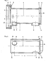
- the housing of the metering device according to the invention shown in FIG. 1 and designated overall by 1 is essentially cylindrical and has a cover 2 with a ventilation hole 3 on the longitudinal end that is to be turned towards the liquid container (not shown in FIG. 1)
- Cylindrical housing 1 also has two circumferential holes essentially in a plane passing through the longitudinal axis 4 of the housing, namely an inlet opening 5 and one. Drain opening 6.
- the housing 1 is equipped with a coupling for connecting the metering device to a liquid container.
- the coupling can consist, for example, of a radial flange 7 on the housing circumference and a union nut 8.
- the opening diameter of the coupling designated overall by 9 is larger by an amount 2e than the diameter of the cylindrical housing 1, wherein e denotes the eccentricity of clutch 9 and housing 1. Because of the eccentricity there is space in the crescent-shaped area of the coupling 9 diametrically opposite the ventilation hole and the circumference of the housing 1 for a channel 10 as a connection between the inside of the container and the inside of the metering housing 1 in the event that the inlet 5, 6 is open.
- the housing 1 also has at its longitudinal end opposite the cover 2 a guide ring 11 with a bead 12 for rotatable fastening, in particular latching, of the dosing chamber to be inserted into the housing 1 according to FIG. 2.
- stop cams 13 and 14 can be provided in the ring 11. which correspond to the CLOSED position (cam 13) and the OPEN position (cam 14).
- the metering chamber 15 has an inlet opening 16 and an outlet opening 17.
- the openings 16 and 17 have the same distance in the direction of the longitudinal axis 4 as the inlet and outlet 5 or 6 of the Ge 1.
- inlet 16 and outlet 17 are offset so far from one another that inlet and outlet 16, 17 of the metering chamber 15 only with either inlet 5 or outlet 6 of housing 1 Can come cover.
- the circumferential angle between the stop cams 13 and 14 in the guide trough 11 according to FIG. 1 corresponds to the circumferential angle between the inlet opening 16 and the outlet opening 17 of the metering chamber 15 protruding flange 19.
- the flange 19 must be snapped into the guide groove 11 of the housing behind the retaining bead 12.
- counter cams 20 and 21 are provided for the OPEN and CLOSED positions.
- a rotary vane 22 is expediently placed on the outside of the base 18, in particular molded on. The rotary vane 22 serves to pivot the metering chamber 15 in the OPEN or CLOSED position relative to the housing 1 during operation.
- the metering chamber 15 is pushed into the housing 1 in the direction of the longitudinal axis 4 until the flange 19 snaps behind the retaining bead 12.
- the dosing device is screwed onto the muzzle thread 23 of a liquid container 24 with the aid of its coupling 9, for example with the aid of the union nut 8 which grips the flange 7.
- the ventilation hole 3 in the lid 2 of the housing 1 is opened.
- a corresponding air volume can therefore flow into the container 24 in the direction of the arrow 26. In this way it is possible to completely fill the dosing chamber 15 from the liquid container 24.
- the metering chamber 15 is filled, the metering process ends. If the wall of the housing and dosing chamber is made entirely or partially of transparent or translucent material, the end of the dosing can be observed with the naked eye.
- the dosing chamber 15 can be rotated relative to the housing with the help of the rotary vane 22 to such an extent that it is not possible for the dosed liquid to flow back via the inlet 5 or 16, but the removal position with the outlet openings 6, 17 made to coincide has not yet been reached.
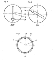
- Fig. 4 shows the relative position of housing 1 and metering chamber 15, in which the drain openings 6, 17 coincide.
- the vent hole 3 of the housing cover 2 is also covered with a web 27 arranged on the inner surface of the metering chamber 15 diametrically opposite the drain opening 17, such that a connection to the inside of the liquid container 24 is not provided when the liquid in the metering device is removed the ventilation hole 3 exists.
- the swivel positions of the rotary wing 22 corresponding to the removal position (metering device OPEN) or the metering position (metering device CLOSED) are shown schematically represented table.
- the indicator arrow 28 connected to the rotary wing 22 points downward in the direction of the drain opening 6 of the housing 1.
- the rotary wing 22 moves from the position according to FIG. 5 into that according to FIG. 6, the stop cams 13 and 21 (FIGS. 1 and 2) collide.
- This relative rotation simultaneously releases the ventilation 3 and, by covering the openings 5 and 16, the inlet.
- the rotary vane 22 can be pivoted by turning it to the left from the position according to FIG. 6 into that according to FIG. 5 until the stop cams 14 and 20 collide, so that the outlet with the openings 6 and 17 is opened and the ventilation hole 3 with Help the web 27 be closed.
Landscapes
- Physics & Mathematics (AREA)
- Fluid Mechanics (AREA)
- General Physics & Mathematics (AREA)
- Containers And Packaging Bodies Having A Special Means To Remove Contents (AREA)
- Catching Or Destruction (AREA)
- Closures For Containers (AREA)
Applications Claiming Priority (2)
| Application Number | Priority Date | Filing Date | Title |
|---|---|---|---|
| DE3502429 | 1985-01-25 | ||
| DE19853502429 DE3502429A1 (de) | 1985-01-25 | 1985-01-25 | Dosiergeraet mit zylindrischem gehaeuse und darin drehbar gelagerter dosierkammer |
Publications (2)
| Publication Number | Publication Date |
|---|---|
| EP0189149A2 true EP0189149A2 (fr) | 1986-07-30 |
| EP0189149A3 EP0189149A3 (fr) | 1987-12-02 |
Family
ID=6260723
Family Applications (1)
| Application Number | Title | Priority Date | Filing Date |
|---|---|---|---|
| EP86100613A Ceased EP0189149A3 (fr) | 1985-01-25 | 1986-01-17 | Dispositif de dosage avec boítier cylindrique et chambre de dosage tournante incorporée |
Country Status (2)
| Country | Link |
|---|---|
| EP (1) | EP0189149A3 (fr) |
| DE (1) | DE3502429A1 (fr) |
Cited By (4)
| Publication number | Priority date | Publication date | Assignee | Title |
|---|---|---|---|---|
| EP0393414A1 (fr) * | 1989-04-20 | 1990-10-24 | Sigismund Laskowski | Système de dosage universel |
| WO2006104465A1 (fr) * | 2005-03-29 | 2006-10-05 | Choon Sen Soon | Appareil de distribution |
| EP1488200A4 (fr) * | 2002-03-04 | 2007-05-02 | Molly Polly Innovations Pty Lt | Robinet regulateur |
| CN109132182A (zh) * | 2018-08-06 | 2019-01-04 | 滕炜 | 一种方便计量的瓶盖组件 |
Family Cites Families (7)
| Publication number | Priority date | Publication date | Assignee | Title |
|---|---|---|---|---|
| DE70950C (de) * | Dr. med. S. SACHS, Arzt, in Berlin N., Brunnenstr. 85 | Medizinmefsflasche | ||
| FR442290A (fr) * | 1912-04-06 | 1912-08-28 | Paul Droin | Appareil pour mesurer des liquides |
| US1442435A (en) * | 1921-11-04 | 1923-01-16 | Harry C Lyons | Dispensing means for beverages containing chocolate, cocoa, etc. |
| GB331018A (en) * | 1929-04-18 | 1930-06-26 | Gaskeil & Chambers Ltd | Improvements in measuring taps |
| FR692524A (fr) * | 1930-03-21 | 1930-11-06 | Bouchon doseur de liquides | |
| GB871389A (en) * | 1959-04-20 | 1961-06-28 | Deb Chemical Proprietaries Ltd | A combined tap and measuring device for liquids or semi-liquids |
| US4293081A (en) * | 1978-08-03 | 1981-10-06 | Dagma Deutsche Automaten Und Getrankemaschinen Gmbh & Co. Kg | Method and device for metered dispensing of liquids, in particular concentrates or syrups, for the production of beverages |
-
1985
- 1985-01-25 DE DE19853502429 patent/DE3502429A1/de not_active Withdrawn
-
1986
- 1986-01-17 EP EP86100613A patent/EP0189149A3/fr not_active Ceased
Cited By (4)
| Publication number | Priority date | Publication date | Assignee | Title |
|---|---|---|---|---|
| EP0393414A1 (fr) * | 1989-04-20 | 1990-10-24 | Sigismund Laskowski | Système de dosage universel |
| EP1488200A4 (fr) * | 2002-03-04 | 2007-05-02 | Molly Polly Innovations Pty Lt | Robinet regulateur |
| WO2006104465A1 (fr) * | 2005-03-29 | 2006-10-05 | Choon Sen Soon | Appareil de distribution |
| CN109132182A (zh) * | 2018-08-06 | 2019-01-04 | 滕炜 | 一种方便计量的瓶盖组件 |
Also Published As
| Publication number | Publication date |
|---|---|
| DE3502429A1 (de) | 1986-07-31 |
| EP0189149A3 (fr) | 1987-12-02 |
Similar Documents
| Publication | Publication Date | Title |
|---|---|---|
| EP1188679B1 (fr) | Fermeture automatique pour récipient élastique déformable | |
| EP0313519B1 (fr) | Installation pour doser et mélanger au moins deux composants réactionnels | |
| DE69306068T2 (de) | Pfropfen zum Verschliessen eines Flüssigkeitsbehälters | |
| EP2632606B1 (fr) | Piston et agencement de cartouche le comprenant | |
| DE102005020460B4 (de) | Rühr- oder Dispergiervorrichtung | |
| DE69719089T2 (de) | Austragkartusche | |
| DE3239784A1 (de) | Doppelbehaelter fuer zwei getrennt aufzubewahrende fluessigkeiten | |
| DE1486690A1 (de) | Behaelter zum Abgeben eines fluessigen oder pulverfoermigen Materials | |
| EP0915737A2 (fr) | Dispositif de fermeture, dispositif de separation et recipient collecteur pour dispositif collecteur | |
| DE10000772A1 (de) | Hydraulikverteiler | |
| EP2218518A2 (fr) | Cartouche à plusieurs composants à usage unique | |
| DE10351565B4 (de) | Selbstschließender Fluidspendeverschluss | |
| DE2644786C3 (de) | Ausgabedüse, insbesondere für flüssige und halbflüssige Substanzen | |
| DE2200730A1 (de) | Vielfachverteiler fuer eine Fluessigkeit | |
| DE3538454A1 (de) | Einstellbarer spenderverschluss | |
| EP0296103A2 (fr) | Fermeture en plastique avec tige centrale d'étanchéité | |
| DE2420175A1 (de) | Elektrisches differentialventil zur fluessigkeitssteuerung | |
| EP0189149A2 (fr) | Dispositif de dosage avec boîtier cylindrique et chambre de dosage tournante incorporée | |
| EP3173349B1 (fr) | Fermeture | |
| DE8207739U1 (de) | Auf einen eine zentrale Austrittsoeffnung aufweisenden Behaelter fuer Fluessigkeiten aufsetzbare Kappe | |
| DE202006014087U1 (de) | Vorrichtung zum Ausbringen und Anmischen von Mehrkomponentenmassen | |
| EP1746041A1 (fr) | Un bouchon rotatif et refermable | |
| EP0087562B1 (fr) | Distributeur pour produits liquides, pâteux ou en poudre | |
| DE8501892U1 (de) | Dosiergerät mit zylindrischem Gehäuse und darin drehbar gelagerter Dosierkammer | |
| CH638453A5 (de) | Ausgaberohr mit kolben zum ausgeben von fliessfaehigen stoffen. |
Legal Events
| Date | Code | Title | Description |
|---|---|---|---|
| PUAI | Public reference made under article 153(3) epc to a published international application that has entered the european phase |
Free format text: ORIGINAL CODE: 0009012 |
|
| AK | Designated contracting states |
Kind code of ref document: A2 Designated state(s): AT BE CH DE FR GB IT LI NL |
|
| PUAL | Search report despatched |
Free format text: ORIGINAL CODE: 0009013 |
|
| AK | Designated contracting states |
Kind code of ref document: A3 Designated state(s): AT BE CH DE FR GB IT LI NL |
|
| 17P | Request for examination filed |
Effective date: 19880526 |
|
| 17Q | First examination report despatched |
Effective date: 19880928 |
|
| STAA | Information on the status of an ep patent application or granted ep patent |
Free format text: STATUS: THE APPLICATION HAS BEEN REFUSED |
|
| 18R | Application refused |
Effective date: 19890225 |
|
| RIN1 | Information on inventor provided before grant (corrected) |
Inventor name: VIERKOETTER, PETER |