EP0189213A2 - Diodensplit-Zeilentransformator - Google Patents
Diodensplit-Zeilentransformator Download PDFInfo
- Publication number
- EP0189213A2 EP0189213A2 EP86100992A EP86100992A EP0189213A2 EP 0189213 A2 EP0189213 A2 EP 0189213A2 EP 86100992 A EP86100992 A EP 86100992A EP 86100992 A EP86100992 A EP 86100992A EP 0189213 A2 EP0189213 A2 EP 0189213A2
- Authority
- EP
- European Patent Office
- Prior art keywords
- diode
- resistor
- winding
- line transformer
- split line
- Prior art date
- Legal status (The legal status is an assumption and is not a legal conclusion. Google has not performed a legal analysis and makes no representation as to the accuracy of the status listed.)
- Withdrawn
Links
- 238000004804 winding Methods 0.000 claims abstract description 35
- 239000003990 capacitor Substances 0.000 claims abstract description 11
- 239000000758 substrate Substances 0.000 claims description 2
- 239000011810 insulating material Substances 0.000 description 1
Images
Classifications
-
- H—ELECTRICITY
- H01—ELECTRIC ELEMENTS
- H01F—MAGNETS; INDUCTANCES; TRANSFORMERS; SELECTION OF MATERIALS FOR THEIR MAGNETIC PROPERTIES
- H01F38/00—Adaptations of transformers or inductances for specific applications or functions
- H01F38/42—Flyback transformers
-
- H—ELECTRICITY
- H01—ELECTRIC ELEMENTS
- H01F—MAGNETS; INDUCTANCES; TRANSFORMERS; SELECTION OF MATERIALS FOR THEIR MAGNETIC PROPERTIES
- H01F5/00—Coils
- H01F5/02—Coils wound on non-magnetic supports, e.g. formers
- H01F2005/022—Coils wound on non-magnetic supports, e.g. formers wound on formers with several winding chambers separated by flanges, e.g. for high voltage applications
Definitions
- the invention relates to a diode split line transformer according to the preamble of claim 1.
- Such a diode split line transformer is known from DE-OS 31 22 589, in which the focusing filter capacitor is connected directly to the diode of the partial winding. It has been found that this filter capacitor has a disturbing influence due to its parallel connection to the winding capacitance by reducing the frequency of the desired harmonics.
- the invention is based on the object of specifying a diode split line transformer in which the tuning of the high-voltage winding is improved.
- the diode split line transformer has a primary winding A with the connections 1 0 and 12.
- the terminal 12 of the primary winding A is connected to a switch of a line output stage, not shown, and the operating voltage U Batt is present at the terminal 10.
- a capacitor K1 is also connected to ground from terminal 10.
- An auxiliary winding B with connections 5 and 6 is arranged on the secondary side of the diode row transformer, which supplies an auxiliary voltage with a relatively low voltage value. Additional auxiliary windings can also be provided.
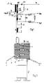
- the high-voltage winding W on the secondary side is divided into three partial windings W1, W2 and W3.
- the individual partial windings W1, W2 and W3 are connected to one another by diodes D1 and D2.
- a further diode D3 is connected to the free connection of the partial winding W3 and the high voltage U h can be taken from its cathode.
- the focusing filter capacitor K and three resistors of a resistor arrangement are connected via the resistor R.
- the two external resistors are adjustable and the focusing voltage U fo or the screen grid voltage Ug 2 can be taken from their grinder.
- the connection 8 of the high-voltage winding W connected to the partial winding W1 is connected to the ground potential.
- Resistor R decouples the parallel connection of focusing filter capacitor K and resistor arrangement from the series connection from partial winding W1 and diode D1.
- the resistance R has a value of approximately 300 to 400 kOhm. This decoupling enables a better tuning of the high-voltage winding W, and this results in a reduction in the internal resistance of the high-voltage source.
- the better tuning of the high-voltage winding W is achieved by reducing the frequency-determining capacitance in the high-voltage winding.
- the focusing voltage is better screened by the low-pass filter formed from the resistor R and the filter capacitor K.
- the winding 2 shows the windings of the diode split line transformer, which are plugged into one another and then inserted into an insulating material housing (not shown).
- the winding 2 is the primary winding A and the auxiliary winding B.
- 3 denotes the bobbin having a number of winding chambers, on which the partial windings of the high-voltage winding W are wound.
- the diodes D1 to D3 connected between the partial windings of the high-voltage winding W are arranged on the circumference of the coil former 3.
- the resistor R is likewise arranged below the diode D1 on the circumference of the coil former 3, which is connected to the focusing filter capacitor K via an insulated line 4.
- the resistor R can also be arranged on the substrate of the resistor arrangement.
- resistor R can also be structurally combined with this bleeder resistor B.
Landscapes
- Engineering & Computer Science (AREA)
- Power Engineering (AREA)
- Details Of Television Scanning (AREA)
- Coils Or Transformers For Communication (AREA)
- Dc-Dc Converters (AREA)
Abstract
Description
- Die Erfindung bezieht sich auf einen Diodensplit-Zeilen--transformator gemäß dem Oberbegriff des Anspruchs 1.
- Aus der DE-OS 31 22 589 ist ein derartiger Diodensplit-Zeilentransformator bekannt, bei dem der Fokussierungs-Siebkondensator direkt mit der Diode der Teilwicklung verbunden ist. Es hat sich herausgestellt, daß dieser Siebkondensator durch seine Parallelschaltung zur Wicklungskapazität einen störenden Einfluß dadurch ausübt, daß er die Frequenz der erwünschten Oberschwingungen herabsetzt.
- Der Erfindung liegt die Aufgabe zugrunde, einen Diodensplit-Zeilentransformator anzugeben, bei dem oie Abstimmung des Hochspannungswickels verbesssert ist.
- Die Lösung dieser Aufgabe erfolgt mit den im Anspruch 1 angegebenen Mitteln. Vorteilhafte Ausgestaltungen der Erfindung sind in den Unteransprüchen 2 bis 5 enthalten.
- Die Erfindung wird nun anhand von einem in den Figuren gezeigten Ausführungsbeispiel näher erläutert. Es zeigt:
- Fig. 1 die Schaltungsanordnung des Diodensplit--Zeilentransformators und
- Fig. 2 schematisch die Wicklungen des Dioden- Split--Zeilentransformators.
- Der Diodensplit-Zeilentransformator weist eine Primärwicklung A mit den Anschlüssen 10 und 12 auf. Der Anschluß 12 der Primärwicklung A ist mit einem nicht dargestellten Schalter einer Zeilenendstufe verbunden und am Anschluß 10 ist die Betriebsspannung UBatt verhanden. Vom Anschluß 10 ist weiterhin ein Kondensator K1 gegen Masse geschaltet.
- Auf der Sekundärseite des Dioden--Zeilentransformators ist eine Hilfswicklung B mit den Anschlüssen 5 und 6 angeordnet, welche eine Hilfsspannung mit verhältnismäßig niedrigem Spannungswert liefert. Es konnen auch weitere Hilfswicklungen vorgesehen sein. Die Hochspannungswicklung W auf der Sekundärseite ist in drei Teilwicklungen W1, W2 und W3 unterteilt. Die einzelnen Teilwicklungen W1, W2 und W3 sind durch Dioden D1 bzw. D2 miteinander verbunden. An den freien Anschluß der Teilwicklung W3 ist eine weitere Diode D3 angeschaltet, an deren Kathode die Hochspannung Uh abgenommen werden kann. Parallel zur Serienschaltung aus der Teilwicklung W1 und der Diode D1 sind über den Widerstand R der Fokussierungs-Siebkondensator K und drei Widerstände einer Widerstandsanordnung angeschaltet. Die beiden äußeren Widerstände sind einstellbar und an ihrem Schleifer kann die Fokussierungsspannung Ufo bzw. die Schirmgitterspannung Ug2 abgenommen werden. Der mit der Teilwicklung W1 verbundene Anschluß 8 der Hochspannungswicklung W ist mit dem Massepotential verbunden.
- Durch den Widerstand R ist die Parallelschaltung aus Fokussierungs-Siebkondensator K und Widerstandsanordnung von der Reihenschaltung aus der Teilwicklung W1 und der Diode D1 entkoppelt. Der Widerstand R weist einen Wert von etwa 300 bis 400 kOhm auf. Durch diese Entkopplung ist eine bessere Abstimmung der Hochspannungswicklung W möglich und dadurch ergibt sich eine Verringerung des Innenwiderstandes der Hochspannungsquelle. Die bessere Abstimmung der Hochspannungswicklung W wird durch die Verringerung der frequenzbestimmenden Kapazität im Hochspannungswickel erreicht. Außerdem wird durch den aus dem Widerstand R und dem Siebkondensator K gebildeten Tiefpaß die Fokussierungsspannung besser gesiebt.
- Fig. 2 zeigt die Wicklungen des Diodensplit--Zeilentransformators, welche ineinandergesteckt und dann in ein nicht dargestelltes Isolierstoffgehäuse eingesetzt werden. Bei dem Wickel 2 handelt es sich um die Primärwicklung A und die Hilfswicklung B. Mit 3 ist der eine Anzahl von Wickelkammern aufweisende Spulenkörper bezeichnet, auf den die Teilwicklungen der Hochspannungswicklung W gewickelt sind. Am Umfang des Spulenkörpers 3 sind die zwischen die Teilwicklungen der Hochspannungswicklung W geschalteten Dioden D1 bis D3 angeordnet. Unterhalb oer Diode D1 ist der Widerstand R ebenfalls am Umfang des Spulenkörpers 3 angeordnet, der über eine isolierte Leitung 4 mit dem Fokussierungs-Siebkondensator K verbunden ist. Der Widerstand R kann aber auch auf dem Substrat der Widerstandsanordnung angeordnet werden.
- Bei einem Diodensplit-Zeilentransformator mit einem Ableitwiderstand B zwischen der Kathode der Diode D3 und der Kathode der Diode D1 kann der Widerstand R auch mit diesem Ableitwiderstand B baulich vereinigt sein.
Claims (5)
Applications Claiming Priority (2)
| Application Number | Priority Date | Filing Date | Title |
|---|---|---|---|
| DE19853502371 DE3502371A1 (de) | 1985-01-25 | 1985-01-25 | Diodensplit-zeilentransformator |
| DE3502371 | 1985-01-25 |
Publications (2)
| Publication Number | Publication Date |
|---|---|
| EP0189213A2 true EP0189213A2 (de) | 1986-07-30 |
| EP0189213A3 EP0189213A3 (de) | 1988-11-09 |
Family
ID=6260684
Family Applications (1)
| Application Number | Title | Priority Date | Filing Date |
|---|---|---|---|
| EP86100992A Withdrawn EP0189213A3 (de) | 1985-01-25 | 1986-01-24 | Diodensplit-Zeilentransformator |
Country Status (6)
| Country | Link |
|---|---|
| EP (1) | EP0189213A3 (de) |
| AU (1) | AU5221786A (de) |
| DE (1) | DE3502371A1 (de) |
| DK (1) | DK36586A (de) |
| ES (1) | ES8705733A1 (de) |
| FI (1) | FI860218A7 (de) |
Cited By (2)
| Publication number | Priority date | Publication date | Assignee | Title |
|---|---|---|---|---|
| EP0291575A3 (en) * | 1987-05-20 | 1989-06-07 | Grundig E.M.V. Elektro-Mechanische Versuchsanstalt Max Grundig | Horizontal deflection transformer |
| DE3902219A1 (de) * | 1989-01-26 | 1990-08-02 | Electronic Werke Deutschland | Kammer-spulenkoerper fuer den hochspannungstransformator eines fernsehempfaengers |
Family Cites Families (4)
| Publication number | Priority date | Publication date | Assignee | Title |
|---|---|---|---|---|
| US3432718A (en) * | 1967-10-19 | 1969-03-11 | Rca Corp | Television focus voltage supply |
| US3495126A (en) * | 1968-05-22 | 1970-02-10 | Rca Corp | Voltage supply |
| JPS5482121A (en) * | 1977-12-14 | 1979-06-30 | Hitachi Ltd | Direct current high voltage generator |
| DE3122589A1 (de) * | 1981-06-06 | 1983-01-05 | Standard Elektrik Lorenz Ag, 7000 Stuttgart | Zeilentransformator fuer fernsehgeraete |
-
1985
- 1985-01-25 DE DE19853502371 patent/DE3502371A1/de not_active Withdrawn
-
1986
- 1986-01-13 AU AU52217/86A patent/AU5221786A/en not_active Abandoned
- 1986-01-17 FI FI860218A patent/FI860218A7/fi not_active Application Discontinuation
- 1986-01-24 DK DK36586A patent/DK36586A/da not_active Application Discontinuation
- 1986-01-24 EP EP86100992A patent/EP0189213A3/de not_active Withdrawn
- 1986-01-25 ES ES551245A patent/ES8705733A1/es not_active Expired
Cited By (2)
| Publication number | Priority date | Publication date | Assignee | Title |
|---|---|---|---|---|
| EP0291575A3 (en) * | 1987-05-20 | 1989-06-07 | Grundig E.M.V. Elektro-Mechanische Versuchsanstalt Max Grundig | Horizontal deflection transformer |
| DE3902219A1 (de) * | 1989-01-26 | 1990-08-02 | Electronic Werke Deutschland | Kammer-spulenkoerper fuer den hochspannungstransformator eines fernsehempfaengers |
Also Published As
| Publication number | Publication date |
|---|---|
| AU5221786A (en) | 1986-07-31 |
| DE3502371A1 (de) | 1986-07-31 |
| FI860218A0 (fi) | 1986-01-17 |
| ES551245A0 (es) | 1987-05-01 |
| FI860218L (fi) | 1986-07-26 |
| EP0189213A3 (de) | 1988-11-09 |
| ES8705733A1 (es) | 1987-05-01 |
| DK36586A (da) | 1986-07-26 |
| DK36586D0 (da) | 1986-01-24 |
| FI860218A7 (fi) | 1986-07-26 |
Similar Documents
| Publication | Publication Date | Title |
|---|---|---|
| DE2351130B2 (de) | Rücklauftransformator | |
| DE2264451C3 (de) | Hochspannungstransformatorenanordnung für Horizontalablenkschaltung | |
| DE2257574B1 (de) | ||
| DE1762629A1 (de) | Hochspannungs-Generatorschaltung | |
| DE2943861A1 (de) | Hochfrequenzgeraet oder -baugruppe | |
| DE69022599T2 (de) | Hochspannungsleistungsversorgung. | |
| DE3879499T2 (de) | Aufgewickeltes kapazitätsbauelement mit kontrollierter impedanz. | |
| EP0189213A2 (de) | Diodensplit-Zeilentransformator | |
| DE4403707A1 (de) | Geregelte Stromversorgungseinheit mit einem elektronischen Transformator | |
| EP0735552B1 (de) | Hochspannungstransformator für einen Fernsehempfänger | |
| EP0047497A1 (de) | Transformator | |
| DE3420915A1 (de) | Frequenzaenderungsvorrichtung | |
| AT218139B (de) | Stufentransformator | |
| DE2452107B2 (de) | Temperaturkompensierte Z-Diodenanordnung | |
| DE2948365A1 (de) | Ruecklauftransformator | |
| DE3318503C2 (de) | Generator zur Hochspannungserzeugung | |
| DE2258132C2 (de) | Rücklaufhochspannungs- und Sägezahnstromgenerator | |
| EP0066803A2 (de) | Zeilentransformator für Fernsehgeräte | |
| DE2832168C2 (de) | Elektrisches Frequenzfilter | |
| DE1904757C3 (de) | Zeilenausgangstransformator mit einer Wicklung zur Hochspannungserzeugung für Fernsehempfänger | |
| EP0269074B1 (de) | Zeilentransformator | |
| DE1512211A1 (de) | Bezugsfrequenzgenerator fuer Farbfernsehempfaenger | |
| DE3334904C1 (de) | Zeilenendtransformator mit eingebautem variablem Hochspannungswiderstand | |
| DE4437444C1 (de) | Ankoppelschaltung | |
| DE3524324C2 (de) |
Legal Events
| Date | Code | Title | Description |
|---|---|---|---|
| PUAI | Public reference made under article 153(3) epc to a published international application that has entered the european phase |
Free format text: ORIGINAL CODE: 0009012 |
|
| AK | Designated contracting states |
Kind code of ref document: A2 Designated state(s): BE DE FR GB IT NL SE |
|
| PUAL | Search report despatched |
Free format text: ORIGINAL CODE: 0009013 |
|
| AK | Designated contracting states |
Kind code of ref document: A3 Designated state(s): BE DE FR GB IT NL SE |
|
| RAP1 | Party data changed (applicant data changed or rights of an application transferred) |
Owner name: NOKIA GRAETZ GESELLSCHAFT MIT BESCHRAENKTER HAFTUN |
|
| STAA | Information on the status of an ep patent application or granted ep patent |
Free format text: STATUS: THE APPLICATION IS DEEMED TO BE WITHDRAWN |
|
| 18D | Application deemed to be withdrawn |
Effective date: 19890510 |
|
| RIN1 | Information on inventor provided before grant (corrected) |
Inventor name: KETTNER, ERICH, DR. |