EP0189213A2 - Transformateur-ligne à enroulements séparés par diodes - Google Patents
Transformateur-ligne à enroulements séparés par diodes Download PDFInfo
- Publication number
- EP0189213A2 EP0189213A2 EP86100992A EP86100992A EP0189213A2 EP 0189213 A2 EP0189213 A2 EP 0189213A2 EP 86100992 A EP86100992 A EP 86100992A EP 86100992 A EP86100992 A EP 86100992A EP 0189213 A2 EP0189213 A2 EP 0189213A2
- Authority
- EP
- European Patent Office
- Prior art keywords
- diode
- resistor
- winding
- line transformer
- split line
- Prior art date
- Legal status (The legal status is an assumption and is not a legal conclusion. Google has not performed a legal analysis and makes no representation as to the accuracy of the status listed.)
- Withdrawn
Links
- 238000004804 winding Methods 0.000 claims abstract description 35
- 239000003990 capacitor Substances 0.000 claims abstract description 11
- 239000000758 substrate Substances 0.000 claims description 2
- 239000011810 insulating material Substances 0.000 description 1
Images
Classifications
-
- H—ELECTRICITY
- H01—ELECTRIC ELEMENTS
- H01F—MAGNETS; INDUCTANCES; TRANSFORMERS; SELECTION OF MATERIALS FOR THEIR MAGNETIC PROPERTIES
- H01F38/00—Adaptations of transformers or inductances for specific applications or functions
- H01F38/42—Flyback transformers
-
- H—ELECTRICITY
- H01—ELECTRIC ELEMENTS
- H01F—MAGNETS; INDUCTANCES; TRANSFORMERS; SELECTION OF MATERIALS FOR THEIR MAGNETIC PROPERTIES
- H01F5/00—Coils
- H01F5/02—Coils wound on non-magnetic supports, e.g. formers
- H01F2005/022—Coils wound on non-magnetic supports, e.g. formers wound on formers with several winding chambers separated by flanges, e.g. for high voltage applications
Definitions
- the invention relates to a diode split line transformer according to the preamble of claim 1.
- Such a diode split line transformer is known from DE-OS 31 22 589, in which the focusing filter capacitor is connected directly to the diode of the partial winding. It has been found that this filter capacitor has a disturbing influence due to its parallel connection to the winding capacitance by reducing the frequency of the desired harmonics.
- the invention is based on the object of specifying a diode split line transformer in which the tuning of the high-voltage winding is improved.
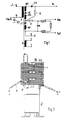
- the diode split line transformer has a primary winding A with the connections 1 0 and 12.
- the terminal 12 of the primary winding A is connected to a switch of a line output stage, not shown, and the operating voltage U Batt is present at the terminal 10.
- a capacitor K1 is also connected to ground from terminal 10.
- An auxiliary winding B with connections 5 and 6 is arranged on the secondary side of the diode row transformer, which supplies an auxiliary voltage with a relatively low voltage value. Additional auxiliary windings can also be provided.
- the high-voltage winding W on the secondary side is divided into three partial windings W1, W2 and W3.
- the individual partial windings W1, W2 and W3 are connected to one another by diodes D1 and D2.
- a further diode D3 is connected to the free connection of the partial winding W3 and the high voltage U h can be taken from its cathode.
- the focusing filter capacitor K and three resistors of a resistor arrangement are connected via the resistor R.
- the two external resistors are adjustable and the focusing voltage U fo or the screen grid voltage Ug 2 can be taken from their grinder.
- the connection 8 of the high-voltage winding W connected to the partial winding W1 is connected to the ground potential.
- Resistor R decouples the parallel connection of focusing filter capacitor K and resistor arrangement from the series connection from partial winding W1 and diode D1.
- the resistance R has a value of approximately 300 to 400 kOhm. This decoupling enables a better tuning of the high-voltage winding W, and this results in a reduction in the internal resistance of the high-voltage source.
- the better tuning of the high-voltage winding W is achieved by reducing the frequency-determining capacitance in the high-voltage winding.
- the focusing voltage is better screened by the low-pass filter formed from the resistor R and the filter capacitor K.
- the winding 2 shows the windings of the diode split line transformer, which are plugged into one another and then inserted into an insulating material housing (not shown).
- the winding 2 is the primary winding A and the auxiliary winding B.
- 3 denotes the bobbin having a number of winding chambers, on which the partial windings of the high-voltage winding W are wound.
- the diodes D1 to D3 connected between the partial windings of the high-voltage winding W are arranged on the circumference of the coil former 3.
- the resistor R is likewise arranged below the diode D1 on the circumference of the coil former 3, which is connected to the focusing filter capacitor K via an insulated line 4.
- the resistor R can also be arranged on the substrate of the resistor arrangement.
- resistor R can also be structurally combined with this bleeder resistor B.
Landscapes
- Engineering & Computer Science (AREA)
- Power Engineering (AREA)
- Details Of Television Scanning (AREA)
- Coils Or Transformers For Communication (AREA)
- Dc-Dc Converters (AREA)
Applications Claiming Priority (2)
| Application Number | Priority Date | Filing Date | Title |
|---|---|---|---|
| DE19853502371 DE3502371A1 (de) | 1985-01-25 | 1985-01-25 | Diodensplit-zeilentransformator |
| DE3502371 | 1985-01-25 |
Publications (2)
| Publication Number | Publication Date |
|---|---|
| EP0189213A2 true EP0189213A2 (fr) | 1986-07-30 |
| EP0189213A3 EP0189213A3 (fr) | 1988-11-09 |
Family
ID=6260684
Family Applications (1)
| Application Number | Title | Priority Date | Filing Date |
|---|---|---|---|
| EP86100992A Withdrawn EP0189213A3 (fr) | 1985-01-25 | 1986-01-24 | Transformateur-ligne à enroulements séparés par diodes |
Country Status (6)
| Country | Link |
|---|---|
| EP (1) | EP0189213A3 (fr) |
| AU (1) | AU5221786A (fr) |
| DE (1) | DE3502371A1 (fr) |
| DK (1) | DK36586A (fr) |
| ES (1) | ES8705733A1 (fr) |
| FI (1) | FI860218A7 (fr) |
Cited By (2)
| Publication number | Priority date | Publication date | Assignee | Title |
|---|---|---|---|---|
| EP0291575A3 (en) * | 1987-05-20 | 1989-06-07 | Grundig E.M.V. Elektro-Mechanische Versuchsanstalt Max Grundig | Horizontal deflection transformer |
| DE3902219A1 (de) * | 1989-01-26 | 1990-08-02 | Electronic Werke Deutschland | Kammer-spulenkoerper fuer den hochspannungstransformator eines fernsehempfaengers |
Family Cites Families (4)
| Publication number | Priority date | Publication date | Assignee | Title |
|---|---|---|---|---|
| US3432718A (en) * | 1967-10-19 | 1969-03-11 | Rca Corp | Television focus voltage supply |
| US3495126A (en) * | 1968-05-22 | 1970-02-10 | Rca Corp | Voltage supply |
| JPS5482121A (en) * | 1977-12-14 | 1979-06-30 | Hitachi Ltd | Direct current high voltage generator |
| DE3122589A1 (de) * | 1981-06-06 | 1983-01-05 | Standard Elektrik Lorenz Ag, 7000 Stuttgart | Zeilentransformator fuer fernsehgeraete |
-
1985
- 1985-01-25 DE DE19853502371 patent/DE3502371A1/de not_active Withdrawn
-
1986
- 1986-01-13 AU AU52217/86A patent/AU5221786A/en not_active Abandoned
- 1986-01-17 FI FI860218A patent/FI860218A7/fi not_active Application Discontinuation
- 1986-01-24 DK DK36586A patent/DK36586A/da not_active Application Discontinuation
- 1986-01-24 EP EP86100992A patent/EP0189213A3/fr not_active Withdrawn
- 1986-01-25 ES ES551245A patent/ES8705733A1/es not_active Expired
Cited By (2)
| Publication number | Priority date | Publication date | Assignee | Title |
|---|---|---|---|---|
| EP0291575A3 (en) * | 1987-05-20 | 1989-06-07 | Grundig E.M.V. Elektro-Mechanische Versuchsanstalt Max Grundig | Horizontal deflection transformer |
| DE3902219A1 (de) * | 1989-01-26 | 1990-08-02 | Electronic Werke Deutschland | Kammer-spulenkoerper fuer den hochspannungstransformator eines fernsehempfaengers |
Also Published As
| Publication number | Publication date |
|---|---|
| AU5221786A (en) | 1986-07-31 |
| DE3502371A1 (de) | 1986-07-31 |
| FI860218A0 (fi) | 1986-01-17 |
| ES551245A0 (es) | 1987-05-01 |
| FI860218L (fi) | 1986-07-26 |
| EP0189213A3 (fr) | 1988-11-09 |
| ES8705733A1 (es) | 1987-05-01 |
| DK36586A (da) | 1986-07-26 |
| DK36586D0 (da) | 1986-01-24 |
| FI860218A7 (fi) | 1986-07-26 |
Similar Documents
| Publication | Publication Date | Title |
|---|---|---|
| DE2351130B2 (de) | Rücklauftransformator | |
| DE2264451C3 (de) | Hochspannungstransformatorenanordnung für Horizontalablenkschaltung | |
| DE2257574B1 (fr) | ||
| DE1762629A1 (de) | Hochspannungs-Generatorschaltung | |
| DE2943861A1 (de) | Hochfrequenzgeraet oder -baugruppe | |
| DE69022599T2 (de) | Hochspannungsleistungsversorgung. | |
| DE3879499T2 (de) | Aufgewickeltes kapazitätsbauelement mit kontrollierter impedanz. | |
| EP0189213A2 (fr) | Transformateur-ligne à enroulements séparés par diodes | |
| DE4403707A1 (de) | Geregelte Stromversorgungseinheit mit einem elektronischen Transformator | |
| EP0735552B1 (fr) | Transformateur à haute tension pour un récepteur de télévision | |
| EP0047497A1 (fr) | Transformateur | |
| DE3420915A1 (de) | Frequenzaenderungsvorrichtung | |
| AT218139B (de) | Stufentransformator | |
| DE2452107B2 (de) | Temperaturkompensierte Z-Diodenanordnung | |
| DE2948365A1 (de) | Ruecklauftransformator | |
| DE3318503C2 (de) | Generator zur Hochspannungserzeugung | |
| DE2258132C2 (de) | Rücklaufhochspannungs- und Sägezahnstromgenerator | |
| EP0066803A2 (fr) | Transformateur de lignes pour récepteurs de télévision | |
| DE2832168C2 (de) | Elektrisches Frequenzfilter | |
| DE1904757C3 (de) | Zeilenausgangstransformator mit einer Wicklung zur Hochspannungserzeugung für Fernsehempfänger | |
| EP0269074B1 (fr) | Transformateur de lignes | |
| DE1512211A1 (de) | Bezugsfrequenzgenerator fuer Farbfernsehempfaenger | |
| DE3334904C1 (de) | Zeilenendtransformator mit eingebautem variablem Hochspannungswiderstand | |
| DE4437444C1 (de) | Ankoppelschaltung | |
| DE3524324C2 (fr) |
Legal Events
| Date | Code | Title | Description |
|---|---|---|---|
| PUAI | Public reference made under article 153(3) epc to a published international application that has entered the european phase |
Free format text: ORIGINAL CODE: 0009012 |
|
| AK | Designated contracting states |
Kind code of ref document: A2 Designated state(s): BE DE FR GB IT NL SE |
|
| PUAL | Search report despatched |
Free format text: ORIGINAL CODE: 0009013 |
|
| AK | Designated contracting states |
Kind code of ref document: A3 Designated state(s): BE DE FR GB IT NL SE |
|
| RAP1 | Party data changed (applicant data changed or rights of an application transferred) |
Owner name: NOKIA GRAETZ GESELLSCHAFT MIT BESCHRAENKTER HAFTUN |
|
| STAA | Information on the status of an ep patent application or granted ep patent |
Free format text: STATUS: THE APPLICATION IS DEEMED TO BE WITHDRAWN |
|
| 18D | Application deemed to be withdrawn |
Effective date: 19890510 |
|
| RIN1 | Information on inventor provided before grant (corrected) |
Inventor name: KETTNER, ERICH, DR. |