EP0189232B1 - Kontinuierlich arbeitende Rundballenpresse - Google Patents
Kontinuierlich arbeitende Rundballenpresse Download PDFInfo
- Publication number
- EP0189232B1 EP0189232B1 EP19860200086 EP86200086A EP0189232B1 EP 0189232 B1 EP0189232 B1 EP 0189232B1 EP 19860200086 EP19860200086 EP 19860200086 EP 86200086 A EP86200086 A EP 86200086A EP 0189232 B1 EP0189232 B1 EP 0189232B1
- Authority
- EP
- European Patent Office
- Prior art keywords
- bale
- guide member
- forming means
- baler
- roll
- Prior art date
- Legal status (The legal status is an assumption and is not a legal conclusion. Google has not performed a legal analysis and makes no representation as to the accuracy of the status listed.)
- Expired
Links
Images


Classifications
-
- A—HUMAN NECESSITIES
- A01—AGRICULTURE; FORESTRY; ANIMAL HUSBANDRY; HUNTING; TRAPPING; FISHING
- A01F—PROCESSING OF HARVESTED PRODUCE; HAY OR STRAW PRESSES; DEVICES FOR STORING AGRICULTURAL OR HORTICULTURAL PRODUCE
- A01F15/00—Baling presses for straw, hay or the like
- A01F15/07—Rotobalers, i.e. machines for forming cylindrical bales by winding and pressing
- A01F15/0705—Arrangements for continuous operation
Definitions
- This invention relates generally to a type of roll baler that is capable of continuously forming roll bales of crop material while moving across a field without stopping to discharge such bales from the roll baler.
- the invention also relates generally to a method of continuously forming roll bales of crop material in a roll baler while moving across a field without stopping for discharging such bales from the roll baler.
- a roll baler and method of this general type are disclosed in US-A 4045 947 assigned to the same assignee as the present application.
- the disclosed baler includes a lower bale forming apron and a. pair of upper bale forming aprons.
- the upper bale forming aprons cooperate with the lower bale forming apron to define front and rear bale forming chambers.
- a bale started in the front chamber reaches a predetermined size, it is transferred to the rear chamber where it is completed. While the completed roll bale is being wrapped with twine and discharged from the rear chamber, another bale is started in the front chamber. This provides for continuous baling operation.
- Movable indexing means are associated with the single upper bale forming apron and include three equiangularly spaced indexing guide members which successively are engageable with the upper bale forming apron for guiding said upper bale forming apron proximate to the lower bale forming apron at a location inbetween the front and rear bale forming chambers.
- the present invention provides a baler for forming roll bales of crop material and which comprises:
- the roll baler of the present invention includes a main body portion and an auxiliary body portion pivotally connected to the main body portion for movement between a closed bale forming position and an open bale discharge position.
- the lower bale forming means are supported on the main body portion and the upper bale forming means are supported on the main body portion and the auxiliary body portion.
- the main body portion includes a pair of sidewalls, and the indexing means include a pair of disks disposed inside the main body portion closely adjacent and parallel to the pair of sidewalls.
- the pair of disks are rotatably mounted on the pair of sidewalls, and the single indexing guide member is connected between the pair of disks at a location radially outwardly from the rotary axis of the disks.
- the upper bale forming means comprise a lower span which is expandable in length around the periphery of a roll bale during formation thereof in the baler.
- the movable indexing guide member when in the home position, is located rearwardly of said lower span and is movable from the home position along said substantially circular path of travel toward a position situated forwardly of said lower span extending around the periphery of the roll bale being formed.
- the roll baler of the present invention also includes drive means engaging the peripheral edges of the pair of disks for rotating the pair of disks in a direction to cause movement of the indexing guide member as already said.
- the drive means comprise sprockets adapted for engagement with teeth formed on the peripheral edges of the discs.
- the sprockets are connected by a cross shaft and an electric clutch and brake device is coupled to one end of said crop shaft.
- the electric clutch and brake device is selectively operable either as a clutch to allow the shaft, the sprockets and the disks stationary.
- a method for forming roll bales of crop material in a baler having: a) upper and lower bale forming means cooperating to define a bale starting zone therebetween; b) drive members associated with respectively the upper and lower bale forming means for moving said bale forming means in directions to roll crop material into a roll bale in the bale starting zone, and c) movable indexing means associated with the upper bale forming means and including an indexing guide member having a home position for guiding the upper bale forming means proximate to the lower bale forming means at the rear of the bale starting zone; the method comprising the steps of:
- the method according to the invention also comprises the step of wrapping the first bale in the baler with wrapping material while starting the second bale in the reformed bale starting zone and prior to discharging said first roll bale from the baler.
- the method also includes the steps of:
- said another position of the single indexing guide member is located part of the way along the substantially circular path of travel and adjacent the drive member for the upper bale forming means.
- a roll baler 10 subject of the present invention is similar to the type disclosed in U.S. Patent No. 3914926 incorporated herein by reference.
- the type of baler disclosed in this patent has been manufactured and sold by the Gehl Company as Model Nos. 1400 and 1600.
- the roll baler 10 includes a main body portion or frame 12 supported by a pair of wheels 14, and an auxiliary body portion or tailgate 16.
- a tongue 18 is provided on the frame 12 for connection to a tractor.
- a pickup device 20 mounted on the frame 12 includes a plurality of tines 22 rotatable about a shaft 23 for engaging and picking up crop material arranged in windrows on the ground.
- the frame 12 includes a pair of sidewalls 13 which are vertically oriented and transversely spaced apart.
- the tailgate 16 includes a pair of side members 17 rigidly connected together by cross members (not shown).
- the side members 17 of the tailgate 16 are pivotally connected by stub shafts 24 to the sidewalls 13 of the frame 12.
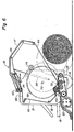
- a pair of hydraulic cylinders 26 are connected between the sidewalls 13 of the frame 12 and the side members 17 of the tailgate 16 for moving the tailgate 16 between the closed position shown in Fig. 1 and the open position shown in Fig. 6.
- Lower bale forming means such as a conveyor 28 in the form of an endless belt extend between the sidewalls 13 of the frame 12 and are supported on front and rear rollers 30 and 32, respectively, which are rotatably carried on the frame 12.
- the upper run 29 of the conveyor 28 is-supported between the front and rear rollers 30, 32 by intermediate rollers 34 and 36 which are also rotatably carried on the frame 12.
- a press-roller 38 extends between and is supported on the sidewalls 13 of the frame 12 directly above the front roller 30 of the conveyor 28 to compress incoming crop material into a mat.
- the press roller 38 and the front roller 30 of the conveyor 28 are connected by conventional drive means (not shown), such as chains and sprockets, to the power take off unit (PTO) of a tractor in a manner to cause rotation of the press roller 38 and the conveyor front roller 30 in the directions indicated in Fig. 1.
- the upper run 29 of the conveyor 28 moves rearwardly from the front roller 30 to the rear roller 32.
- a plurality of guide members or rollers 40, 42, 44 and 46 extend between and are rotatably supported on the sidewalls 13 of the frame 12.
- Another plurality of guide members or rollers 48, 50, 52, 54, 56 and 58 extend between and are rotatably supported on the side members 17 of the tailgate 16.
- Shuttle members 60 are slidably mounted on the sidewalls 13 of the frame 12 for back and forth movement in a substantially horizontal direction near the top of the frame 12.
- a pair of guide members or rollers 62 and 64 extend between and are rotatably carried by the shuttle members 60.
- Upper bale forming means preferably comprised of a series of endless belts 66 extend around the aforementioned guide members or rollers in a side-by-side, transversely spaced apart arrangement between the sidewalls 13 of the frame 12 and also between the side members 17 of the tailgate 16.
- the rollers 40 and 44 are connected to the PTO of a tractor by drive means (not shown) in a conventional manner to drive the belts 66 in the direction and along the path indicated in Fig. 1.
- a conventional clutch mechanism (not shown), which may be electrically, mechanically or hydraulically operated, is provided in the drive means (not shown) to the drive rollers 40 and 44 to enable the drive rollers 40 and 44 to be disengaged from the tractor PTO to interrupt movement of the belts 66.
- the shuttle members 60 are urged forwardly toward the phantom position shown in Fig. 1 by spring mechanisms (not shown) to maintain a certain amount of tension in the belts 66.
- a pair of disks 68 are disposed inside the frame 12 closely adjacent and parallel to the sidewalls 13 thereof.
- Each disk 68 is in the form of a flat circular plate.
- the disks 68 are fixed at their centers to stub shafts 70 which in turn are rotatably mounted in bearing members located in the sidewalls 13 of the frame 12.
- An indexing guide member in the form of a roller 72 is rotatably connected between the disks 68 at a location radially outwardly from the stub shafts 70.
- the indexing roller 72 extends transversely of the baler 10.
- Teeth 74 formed on the peripheral edges of the disks 68 are adapted for engagement with sprockets 76 rotatably mounted on brackets 78 attached to the sidewalls 13 of the frame 12.
- the sprockets 76 are connected by a cross shaft 80.
- One end of the cross shaft 80 is coupled to an electric clutch and brake device (not shown) such as Model No. IXC-931 manufactured by Warner Electric Corporation.
- This electric clutch - and brake device may be selectively operated as either a clutch to allow the shaft 80 and the sprockets 76 to be rotated or as a brake to hold the shaft 80 and the sprockets 76 stationary.
- the indexing roller 72 is provided inside the loop formed by the endless belts 66 of the upper bale forming means. It also will be seen that, when the indexing roller 72 is in the position shown in Figure 1, (called hereafter the home position), the belts pass underneath this indexing roller 72 in close proximity to the upper run 29 of the conveyor 28 so that a lower span 67 of the belts 66 running from the indexing roller 72 to the drive roller 40 moves in substantially the opposite direction as the upper run 29 of the conveyor 28. This relationship between the direction of movement of the lower span 67 of the belts 66 and the direction of movement of the upper run 29 of the conveyor 28 causes crop material to be coiled or wrapped in a manner to effectively start a roll bale.
- the lower span 67 of the belts 66 is expandable in length during bale formation.
- the baler 10 is towed across a field by a tractor.
- the pickup device 20 delivers crop material between the press roller 38 and the front of the conveyor 28.
- the upper run 29 of the conveyor 28 carries the crop material rearwardly into a bale starting zone 69 where it is engaged by the lower span 67 of the belts 66 which causes coiling of the crop material and formation of the core of a roll bale.
- the electric clutch and brake device (not shown) on the shaft 80 is operated as a brake so that the indexing means including the disks 68 and the indexing roller 72 are held stationary by the sprockets 76 with the indexing roller 72 being located in the home position as shown in Fig.
- the electric clutch and brake device (not shown) on the shaft 80 is operated as a clutch so that the sprockets 76 are driven via the shaft 80 thereby causing rotation of the indexing means including the disks 68 and the indexing guide roller 72 in the direction indicated in Fig. 2 whereby the indexing roller 72 is moved from its home position in a substantially circular path of travel generally about the periphery of the bale.
- the disks 68 together with the indexing roller 72 thereon are rotated through a full 360 degrees revolution. Initial rotation of the disks 68 moves the indexing roller 72 out of engagement with the belts 66 as seen in Fig. 3 wile crop material continues to be added to the bale.
- the belts 66 remain disconnected from the tractor PTO until the disks 68 complete one full 360° revolution and the indexing roller 72 returns to its home position as shown in Fig. 5. In practice, this takes only a very short while and does not necessitate interruption of the forward movement of the roll baler across the field. In other words, the pick-up device 20 continues to pick up crop material from the field and deliver it to the press roll 38. As the indexing roller 72 is moved across the throat of the bale chamber, further crop material which is supplied by the pick-up device 20, is accumulated in the zone forwardly of the indexing roller 72 and between the upper run 29 of the lower belt 28 and the lower span 67 of the upper belts 66 between the indexing roller 72 and the drive roller 40. This zone is the bale starting zone 69 already described.
- the bale starting zone 69 is consequently reformed and the belts 66 are reconnected to the tractor PTO.
- a new bale is then started in the bale starting zone 69 while the previously completed bale positioned rearwardly of the newly formed bale starting zone 69, is being wrapped in a net or other wrapping material in a conventional manner.
- the tailgate 16 is moved to its open position as shown in Fig. 6 by extending the hydraulic cylinders 26, and the completed bale is discharged.
- the tailgate 16 is moved back to its closed position of Fig. 1 and the baling operation continues without interruption.
- the present invention is not limited to the particular roll baler 10 which is derived from the roll baler disclosed in U.S. Patent No. 3 914 926. Accordingly, the present invention may be incorporated in other types of roll balers to form continuous roll balers.
- the invention provides a continuous roll baler which is simple in design and relatively inexpensive to manufacture and yet enables a continuous roll baling operation, which in turn results in a substantially increased ouput.
- the present invention basically provides a «one chamber» continuous roll baler, which is in contrast with the prior art continuous roll balers which have two chambers of one form or another (see e.g. EP 0 064117).
- a single bale starting chamber of zone 69 is provided which «grows» together with a bale being formed therein till the said bale reaches its desired maximum size.
- the bale forming chamber or zone is relocated in an ingenious manner and returns to its original or starting dimension and shape forwardly of the completed bale, which still is held in the baler for a short while. This is sufficient for wrapping said bale with a wrapping material of any type.
- the baler subject of the invention basically is a «one chamber» continuous roll baler
- the design thereof nevertheless allows two chambers to be formed and maintained for a short while during the bale formation. Indeed, a full size bale chamber is maintained alongside and together with the relocation or reformation of the bale starting zone or-chamber in its original shape and dimension during the period of time from the moment the bale reaches its full size until it is being discharged following the wrapping thereof in the machine. This period of time is only a fraction of the time needed for forming a roll bale.
Landscapes
- Life Sciences & Earth Sciences (AREA)
- Environmental Sciences (AREA)
- Harvester Elements (AREA)
- Storage Of Harvested Produce (AREA)
Claims (25)
dass die Weiterschalteinrichtungen (68, 72) während der Bildung eines Rundballens in der Rundballenpresse so betätigt werden, dass sie das einzige Weiterschalt-Führungsteil (72) von der Ausgangsposition über eine volle 360°-Drehung um die Bewegungsbahn herum und zurück zur Ausgangsposition bewegen.
Applications Claiming Priority (8)
| Application Number | Priority Date | Filing Date | Title |
|---|---|---|---|
| US694868 | 1976-06-10 | ||
| US694864 | 1985-01-25 | ||
| US06/694,868 US4597249A (en) | 1985-01-25 | 1985-01-25 | Method of forming roll bales |
| US06/694,886 US4584827A (en) | 1985-01-25 | 1985-01-25 | Drive mechanism for roll baler |
| US694866 | 1985-01-25 | ||
| US06/694,864 US4597248A (en) | 1985-01-25 | 1985-01-25 | Method of operating a roll baler |
| US06/694,866 US4597254A (en) | 1985-01-25 | 1985-01-25 | Continuous roll baler |
| US694886 | 1996-08-09 |
Publications (2)
| Publication Number | Publication Date |
|---|---|
| EP0189232A1 EP0189232A1 (de) | 1986-07-30 |
| EP0189232B1 true EP0189232B1 (de) | 1989-09-06 |
Family
ID=27505455
Family Applications (1)
| Application Number | Title | Priority Date | Filing Date |
|---|---|---|---|
| EP19860200086 Expired EP0189232B1 (de) | 1985-01-25 | 1986-01-21 | Kontinuierlich arbeitende Rundballenpresse |
Country Status (2)
| Country | Link |
|---|---|
| EP (1) | EP0189232B1 (de) |
| DE (1) | DE3665388D1 (de) |
Families Citing this family (1)
| Publication number | Priority date | Publication date | Assignee | Title |
|---|---|---|---|---|
| DE3710550C1 (de) * | 1987-03-30 | 1988-06-30 | Zweegers & Zonen P J | Rollballenpresse fuer Erntegut |
Family Cites Families (3)
| Publication number | Priority date | Publication date | Assignee | Title |
|---|---|---|---|---|
| FR2368214A1 (fr) * | 1976-10-19 | 1978-05-19 | Rivierre Casalis | Presse a fourrage pour la production de balles roulees |
| DE3166911D1 (en) * | 1981-05-06 | 1984-12-06 | Deere John | Continuously operable hay-rolling machine |
| US4517891A (en) * | 1983-11-29 | 1985-05-21 | Sperry Corporation | Control linkage for continuous roll baling machine |
-
1986
- 1986-01-21 EP EP19860200086 patent/EP0189232B1/de not_active Expired
- 1986-01-21 DE DE8686200086T patent/DE3665388D1/de not_active Expired
Also Published As
| Publication number | Publication date |
|---|---|
| EP0189232A1 (de) | 1986-07-30 |
| DE3665388D1 (en) | 1989-10-12 |
Similar Documents
| Publication | Publication Date | Title |
|---|---|---|
| US4597254A (en) | Continuous roll baler | |
| US4212149A (en) | Crop baling machines | |
| EP0954959B1 (de) | Rundballenerzeugungvorrichtung | |
| GB2111903A (en) | Round bale baler | |
| EP0337006B1 (de) | Rundballenpresse | |
| US4205513A (en) | Ground-rolling forwardly-directed rotary baler | |
| CA1181985A (en) | Ejection mechanism for a round baler | |
| US4336750A (en) | Stray crop buildup expeller for rotary balers | |
| US5598690A (en) | Tailgate latching apparatus for a round baler | |
| US5419253A (en) | Round bale wrapping method including wrapping with self-adhering tape | |
| US3004377A (en) | Baling machine | |
| AU669485B2 (en) | Round baler having anti-wrapping core starter | |
| US4597249A (en) | Method of forming roll bales | |
| EP0339730B1 (de) | Rundballenpresse mit variabler Kammer und Schleppvorrichtung | |
| EP0235787B1 (de) | Maschine zur Bildung von Rundballen | |
| US4567718A (en) | Round bale forming machine with pickup disconnect mechanism | |
| US4584827A (en) | Drive mechanism for roll baler | |
| EP0189232B1 (de) | Kontinuierlich arbeitende Rundballenpresse | |
| EP0087432B1 (de) | Ballenpresse | |
| US4597248A (en) | Method of operating a roll baler | |
| US6722100B1 (en) | Simplified wrap material dispenser for crop bales | |
| CA1271405A (en) | Machine for forming cylindrical bales of crop | |
| EP0672340B1 (de) | Vorrichtung und Verfahren zur Rundballeneinwicklung | |
| EP0316506B1 (de) | Rundballenmaschine | |
| US4993217A (en) | Machine for forming cylindrical bales of crop |
Legal Events
| Date | Code | Title | Description |
|---|---|---|---|
| PUAI | Public reference made under article 153(3) epc to a published international application that has entered the european phase |
Free format text: ORIGINAL CODE: 0009012 |
|
| 17P | Request for examination filed |
Effective date: 19860121 |
|
| AK | Designated contracting states |
Kind code of ref document: A1 Designated state(s): DE FR GB IT |
|
| RIN1 | Information on inventor provided before grant (corrected) |
Inventor name: CAMPBELL,WILLIS R. Inventor name: BOWDON, DONALD F., JR. Inventor name: UHLAND, FRANCIS L. Inventor name: MERKEY, JOHN A. |
|
| RAP1 | Party data changed (applicant data changed or rights of an application transferred) |
Owner name: NEW HOLLAND INC. |
|
| 17Q | First examination report despatched |
Effective date: 19880520 |
|
| RAP1 | Party data changed (applicant data changed or rights of an application transferred) |
Owner name: FORD NEW HOLLAND, INC. (A DELAWARE CORP.) |
|
| GRAA | (expected) grant |
Free format text: ORIGINAL CODE: 0009210 |
|
| AK | Designated contracting states |
Kind code of ref document: B1 Designated state(s): DE FR GB IT |
|
| PG25 | Lapsed in a contracting state [announced via postgrant information from national office to epo] |
Ref country code: IT Free format text: LAPSE BECAUSE OF FAILURE TO SUBMIT A TRANSLATION OF THE DESCRIPTION OR TO PAY THE FEE WITHIN THE PRE;WARNING: LAPSES OF ITALIAN PATENTS WITH EFFECTIVE DATE BEFORE 2007 MAY HAVE OCCURRED AT ANY TIME BEFORE 2007. THE CORRECT EFFECTIVE DATE MAY BE DIFFERENT FROM THE ONE RECORDED.SCRIBED TIME-LIMIT Effective date: 19890906 |
|
| REF | Corresponds to: |
Ref document number: 3665388 Country of ref document: DE Date of ref document: 19891012 |
|
| ET | Fr: translation filed | ||
| PLBE | No opposition filed within time limit |
Free format text: ORIGINAL CODE: 0009261 |
|
| STAA | Information on the status of an ep patent application or granted ep patent |
Free format text: STATUS: NO OPPOSITION FILED WITHIN TIME LIMIT |
|
| 26N | No opposition filed | ||
| PGFP | Annual fee paid to national office [announced via postgrant information from national office to epo] |
Ref country code: GB Payment date: 19920110 Year of fee payment: 7 |
|
| PGFP | Annual fee paid to national office [announced via postgrant information from national office to epo] |
Ref country code: DE Payment date: 19920111 Year of fee payment: 7 |
|
| PGFP | Annual fee paid to national office [announced via postgrant information from national office to epo] |
Ref country code: FR Payment date: 19920114 Year of fee payment: 7 |
|
| PG25 | Lapsed in a contracting state [announced via postgrant information from national office to epo] |
Ref country code: GB Effective date: 19930121 |
|
| GBPC | Gb: european patent ceased through non-payment of renewal fee |
Effective date: 19930121 |
|
| PG25 | Lapsed in a contracting state [announced via postgrant information from national office to epo] |
Ref country code: FR Effective date: 19930930 |
|
| PG25 | Lapsed in a contracting state [announced via postgrant information from national office to epo] |
Ref country code: DE Effective date: 19931001 |
|
| REG | Reference to a national code |
Ref country code: FR Ref legal event code: ST |