EP0189288A2 - Connecteur blindé et assemblage - Google Patents
Connecteur blindé et assemblage Download PDFInfo
- Publication number
- EP0189288A2 EP0189288A2 EP86300310A EP86300310A EP0189288A2 EP 0189288 A2 EP0189288 A2 EP 0189288A2 EP 86300310 A EP86300310 A EP 86300310A EP 86300310 A EP86300310 A EP 86300310A EP 0189288 A2 EP0189288 A2 EP 0189288A2
- Authority
- EP
- European Patent Office
- Prior art keywords
- contact
- housing
- header
- shielded
- cavity
- Prior art date
- Legal status (The legal status is an assumption and is not a legal conclusion. Google has not performed a legal analysis and makes no representation as to the accuracy of the status listed.)
- Granted
Links
- 229910052751 metal Inorganic materials 0.000 description 6
- 239000002184 metal Substances 0.000 description 6
- 238000003780 insertion Methods 0.000 description 3
- 230000037431 insertion Effects 0.000 description 3
- 239000004020 conductor Substances 0.000 description 2
- 230000014759 maintenance of location Effects 0.000 description 2
- 230000013011 mating Effects 0.000 description 2
- 229910000906 Bronze Inorganic materials 0.000 description 1
- RYGMFSIKBFXOCR-UHFFFAOYSA-N Copper Chemical compound [Cu] RYGMFSIKBFXOCR-UHFFFAOYSA-N 0.000 description 1
- OAICVXFJPJFONN-UHFFFAOYSA-N Phosphorus Chemical compound [P] OAICVXFJPJFONN-UHFFFAOYSA-N 0.000 description 1
- 229910000831 Steel Inorganic materials 0.000 description 1
- 229910052782 aluminium Inorganic materials 0.000 description 1
- XAGFODPZIPBFFR-UHFFFAOYSA-N aluminium Chemical compound [Al] XAGFODPZIPBFFR-UHFFFAOYSA-N 0.000 description 1
- 239000010974 bronze Substances 0.000 description 1
- 238000006243 chemical reaction Methods 0.000 description 1
- 230000000295 complement effect Effects 0.000 description 1
- 229910052802 copper Inorganic materials 0.000 description 1
- 239000010949 copper Substances 0.000 description 1
- KUNSUQLRTQLHQQ-UHFFFAOYSA-N copper tin Chemical compound [Cu].[Sn] KUNSUQLRTQLHQQ-UHFFFAOYSA-N 0.000 description 1
- 239000003989 dielectric material Substances 0.000 description 1
- 230000000694 effects Effects 0.000 description 1
- 238000007373 indentation Methods 0.000 description 1
- 229920003023 plastic Polymers 0.000 description 1
- 239000004033 plastic Substances 0.000 description 1
- 229920000728 polyester Polymers 0.000 description 1
- 230000000750 progressive effect Effects 0.000 description 1
- 239000010959 steel Substances 0.000 description 1
Images


Classifications
-
- H—ELECTRICITY
- H01—ELECTRIC ELEMENTS
- H01R—ELECTRICALLY-CONDUCTIVE CONNECTIONS; STRUCTURAL ASSOCIATIONS OF A PLURALITY OF MUTUALLY-INSULATED ELECTRICAL CONNECTING ELEMENTS; COUPLING DEVICES; CURRENT COLLECTORS
- H01R24/00—Two-part coupling devices, or either of their cooperating parts, characterised by their overall structure
- H01R24/28—Coupling parts carrying pins, blades or analogous contacts and secured only to wire or cable
- H01R24/30—Coupling parts carrying pins, blades or analogous contacts and secured only to wire or cable with additional earth or shield contacts
-
- H—ELECTRICITY
- H01—ELECTRIC ELEMENTS
- H01R—ELECTRICALLY-CONDUCTIVE CONNECTIONS; STRUCTURAL ASSOCIATIONS OF A PLURALITY OF MUTUALLY-INSULATED ELECTRICAL CONNECTING ELEMENTS; COUPLING DEVICES; CURRENT COLLECTORS
- H01R12/00—Structural associations of a plurality of mutually-insulated electrical connecting elements, specially adapted for printed circuits, e.g. printed circuit boards [PCB], flat or ribbon cables, or like generally planar structures, e.g. terminal strips, terminal blocks; Coupling devices specially adapted for printed circuits, flat or ribbon cables, or like generally planar structures; Terminals specially adapted for contact with, or insertion into, printed circuits, flat or ribbon cables, or like generally planar structures
-
- H—ELECTRICITY
- H01—ELECTRIC ELEMENTS
- H01R—ELECTRICALLY-CONDUCTIVE CONNECTIONS; STRUCTURAL ASSOCIATIONS OF A PLURALITY OF MUTUALLY-INSULATED ELECTRICAL CONNECTING ELEMENTS; COUPLING DEVICES; CURRENT COLLECTORS
- H01R13/00—Details of coupling devices of the kinds covered by groups H01R12/70 or H01R24/00 - H01R33/00
- H01R13/648—Protective earth or shield arrangements on coupling devices, e.g. anti-static shielding
- H01R13/658—High frequency shielding arrangements, e.g. against EMI [Electro-Magnetic Interference] or EMP [Electro-Magnetic Pulse]
- H01R13/6581—Shield structure
- H01R13/6585—Shielding material individually surrounding or interposed between mutually spaced contacts
-
- H—ELECTRICITY
- H01—ELECTRIC ELEMENTS
- H01R—ELECTRICALLY-CONDUCTIVE CONNECTIONS; STRUCTURAL ASSOCIATIONS OF A PLURALITY OF MUTUALLY-INSULATED ELECTRICAL CONNECTING ELEMENTS; COUPLING DEVICES; CURRENT COLLECTORS
- H01R13/00—Details of coupling devices of the kinds covered by groups H01R12/70 or H01R24/00 - H01R33/00
- H01R13/648—Protective earth or shield arrangements on coupling devices, e.g. anti-static shielding
- H01R13/658—High frequency shielding arrangements, e.g. against EMI [Electro-Magnetic Interference] or EMP [Electro-Magnetic Pulse]
- H01R13/6591—Specific features or arrangements of connection of shield to conductive members
- H01R13/6594—Specific features or arrangements of connection of shield to conductive members the shield being mounted on a PCB and connected to conductive members
- H01R13/6595—Specific features or arrangements of connection of shield to conductive members the shield being mounted on a PCB and connected to conductive members with separate members fixing the shield to the PCB
Definitions
- This invention relates, in general, to electrical connectors and, more particularly, it relates to shielded headers used to connect electrically a cable connector to a printed circuit board or other electrical device while restricting the emission of electromagnetic energy therefrom to prevent interference with other electrical devices.
- a known shielded header has a dielectric housing provided with a cavity open at its top, the cavity being bounded by elongate side walls, end walls and a floor.
- a plurality of contact pins are mounted in the cavity and project through the floor and outwardly from the housing.
- a female connector with a cable fits inside the cavity and established connection therein between the pins and contacts of the connector.
- US-A- 4 386 814 describes a kit for converting a connector receiving apertures in a panel to a shielded pin receptacle. While this kit appears to provide the required shielding, it requires extensive work to make the conversion.
- a general object of the invention is to provide an improved form of shielded header.
- the present invention provides a shielded header for providing electrical connection and restricting the emission of high frequency electromagnetic energy; said header comprising a dielectric housing provided with a cavity open at its top, the cavity being bounded by elongate side walls and a floor, a plurality of contact pins mounted in the cavity and projecting through the floor and outwardly from the housing; wherein at least one electrically conductive spring contact is mounted to the housing for establishing grounding exteriorly of the header and therealong, the contacts having a plurality of contact beams projecting upward in a common plane, so that each beam lies at the interior of the cavity for contact with a female connector insertable into the cavity.
- the invention also provides a shielded header for establishing electrical connection between a cable and a printed circuit board and for restricting the emission of high frequency electromagnetic energy, said header comprising a dielectric housing having a cavity open at its top, the cavity being enclosed by front and rear elongate side walls and two end walls together with a floor perforated with a plurality of through holes each accommodating an electrically conductive pin; wherein side skirts extend downward from the side wall and are provided with a plurality of vertical grooves; an elongate ground strip is mounted between the side skirts, the ground strip having a plurality of notches aligned with the lower ends of the grooves; electrically conductive spring contacts are mounted in the housing each spring contact having contact beams projecting upward in a common plane, a plurality of locking tabs projecting away from the contact beams and a plurality of shelf tabs projecting away from the contact beams and located between the locking tabs, the spring contacts being disposed so that each contact beam is in contact with an interior side of the side walls one leg of each
- the invention provides a shielded preassembled header that provides excellent protection against the escape of electromagnetic energy. It also has a low insertion force with respect to the female connector, low contact wear, adaptability to any length header and with metal parts suitable for high speed stamping.
- the header comprises a dielectric housing having an inner cavity containing vertical through holes for receiving standard electrically conductive pins. Usually these pins are set out in a double row.
- the exterior of the housing has rear grooves and front grooves for receiving a pair of metal spring contacts which are slid in the grooves between rib structures on the exterior of the housing and into a series of holes leading to the interior of the housing.
- each beam on the metal spring contact is exposed within the interior of the housing so that ground contact can be made with a female cable connector engaged to the pins within the housing.
- a series of ground bars on the metal spring contact protrude to the exterior of the housing for chassis grounding.
- a ground strip attached at the bottom exterior of the housing provides additional ground to a circuit board.
- a filter can be contained within the housing around the electrically conductive pins.
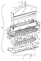
- a shielded header assembly 10 constructed in accordance with the invention also comprises a female cable connector 12 containing female terminals (not shown) of sufficient number to engage pins 14 mounted within through holes 68 in a floor or base wall of a dielectric housing 16 forming a shielded header.
- One end of connector 12 is attached to an electrical cable 18 and the other end fits within a cavity 20 of the housing 16.
- the cavity 20 is defined by front and rear elongate side walls 24 (Figs. 4 to 6) end walls and the base wall.
- a contact receptacle 22 on the exterior of connector 12 makes electrical contact with contact beams 62 of spring contacts 44 depicted in Figure 8 on one of the two interior sidewalls 24 defining the cavity 20.
- the housing 16 contains through holes 26 and 28 on L-shaped end portions 30 and 32 respectively for use in bolting the header housing 16 with bolts 80 onto a computer chassis 78 (Figs. 5, 7 and 8) or other electrical device employing a printed circuit board 34 directly beneath the housing 16. These end portions 30, 32 also have U-shaped openings 35 for use in bolting the housing 16 to an alternative disposition.
- Figs. 2 and 3 depict the header assembly in this alternative mode with the printed circuit board 42 alongside the housing 16.
- a ground strip 36 is affixed to the bottom 38 of the housing 16 with the aid of the spring contacts 44 as described hereinafter.
- the ground strip 36 has an open mid-portion 40 to accommodate the pins 14 which pass therethrough and enter holes 42 in the circuit board 34.
- Notches 41 on both edges of the ground strip 36 accommodate the beams 62 formed on the elongate conductive metal spring contacts 44.
- Holes 27 and 29 in the strip 36 align with the holes 26 and 28 respectively in the end portions of the housing 16 while holes 31 in the strip 36 align with the U-shaped openings 35 on housing 16.
- the spring contacts 44 are inserted into grooves 46 and grooves 48 independing side skirts of the rear and front sidewalls 24 of the housing 16.
- Vertical ribs 50 on both the rear and front sides of housing 16 delineate the grooves 46 and 48.
- each contact 44 has a main body portion or carrier provided with indexing holes 52 spaced therealong and aligned with the contact beams 62 extending therefrom.
- Locking tabs 54 project from the carrier opposite the respective contact beams 62.
- Ground bars 58 extend from the carrier between the contact beams 62 and shelf tabs 56 project from the carrier in the opposite direction to the ground bars 58.
- Retention tabs or barbs 60 are formed at the bases of the contact beams 62 at the juncture with the carrier.
- each beam 62 has one end 64 inserted into a slot 66 in the associated interior wall 24 of housing 16.
- Each contact 44 is inserted into the housing 16 by sliding its beams 62 into the appropriate groove 46, 48 and between the ribs 50.
- the beam 62 then passes through the appropriate opening 74 in the housing 16 so that the ends 64 of the beams 62 project into the associated slot 66 in the interior wall 24 of housing 16 as shown in Figs. 4, 5 and 6.
- the beams 62 are stressed or pre-loaded so as to reduce the insertion force on the cable connector 12.
- the ground bars 58 come to rest at the L-shaped indentations in the housing 16 just above the grooves 46, 48.
- the locking tabs 54 are folded over the lower side of the ground strip 36 to lock it into position.
- the shelf tabs 56 provide compliant contact with the other side of the ground strip 36.
- the ground bars 58 project laterally at right-angles from the housing 16 just below the associated wall 24 and contact the chassis 78.
- the ground bars 58 make efficient contact with the chassis 78 as shown in Fig. 5 and ensure grounding along the entire side of the header instead of primarily at the ends as is the case with the prior art header shown in Fig. 9.
- the tabs 60 serve to anchor the strip contacts 44 into the plastics walls of the housing 16.
- the contact pins 14a are L-shaped with portions extending laterally of the housing 16 as opposed to the pins 14 in the embodiment of Fig. 1 which are straight.
- the pins 14a engage in the holes 42 in the circuit board 34 and the contacts 44 are again inserted into the housing 16 so that ground bars 58 locate to the housing 16 as before.
- the housing 16 can be made from any suitable dielectric material such as polycarbontate or polyester.
- the pins 14, 14a, and contacts 44 are usually phosphor bronze or some other conductive metal and the ground strip 36 can be made out of any conductive material such as steel, copper, aluminum, etc.
- Fig. 7 depicts an alternative mounting arrangement where a further frame structure 84 is fixed to the chassis 78 with bolts 82.
- Latch receptacle designated 76 in Figs. 4 and 6 in the housing 16 is an optional feature.
- Fig. 5 also shows as another optional variation, a filter 70 in the header to provide additional protection against the escape of electromagnetic energy.
- the pins 14 are soldered at 72 to the filter 70.
- Our European patent applications 84 302 143.7 (EP-A-0123457) and 84 302 142.9 (EP-A-0124264) describe suitable filter structures.
Landscapes
- Details Of Connecting Devices For Male And Female Coupling (AREA)
- Coupling Device And Connection With Printed Circuit (AREA)
- Multi-Conductor Connections (AREA)
- Paper (AREA)
- Golf Clubs (AREA)
- Supporting Of Heads In Record-Carrier Devices (AREA)
- Insulated Conductors (AREA)
Priority Applications (1)
| Application Number | Priority Date | Filing Date | Title |
|---|---|---|---|
| AT86300310T ATE74473T1 (de) | 1985-01-18 | 1986-01-17 | Abgeschirmte verbindungsleiste und zusammenbau. |
Applications Claiming Priority (2)
| Application Number | Priority Date | Filing Date | Title |
|---|---|---|---|
| US692957 | 1976-06-04 | ||
| US06/692,957 US4601527A (en) | 1985-01-18 | 1985-01-18 | Shielded header and cable assembly |
Publications (3)
| Publication Number | Publication Date |
|---|---|
| EP0189288A2 true EP0189288A2 (fr) | 1986-07-30 |
| EP0189288A3 EP0189288A3 (en) | 1988-06-22 |
| EP0189288B1 EP0189288B1 (fr) | 1992-04-01 |
Family
ID=24782755
Family Applications (1)
| Application Number | Title | Priority Date | Filing Date |
|---|---|---|---|
| EP86300310A Expired - Lifetime EP0189288B1 (fr) | 1985-01-18 | 1986-01-17 | Connecteur blindé et assemblage |
Country Status (12)
| Country | Link |
|---|---|
| US (1) | US4601527A (fr) |
| EP (1) | EP0189288B1 (fr) |
| JP (1) | JPS61171073A (fr) |
| KR (1) | KR900000462B1 (fr) |
| AT (1) | ATE74473T1 (fr) |
| AU (1) | AU577750B2 (fr) |
| BR (1) | BR8600104A (fr) |
| CA (1) | CA1235198A (fr) |
| DE (1) | DE3684615D1 (fr) |
| HK (1) | HK58892A (fr) |
| MX (1) | MX159886A (fr) |
| SG (1) | SG57592G (fr) |
Cited By (10)
| Publication number | Priority date | Publication date | Assignee | Title |
|---|---|---|---|---|
| US4808125A (en) * | 1987-08-31 | 1989-02-28 | Amp Incorporated | Connector assembly with diecast housing and drawn shell |
| EP0268441A3 (en) * | 1986-11-18 | 1989-07-26 | E.I. Du Pont De Nemours And Company | Terminator for multiple electrical conductors |
| EP0403106A1 (fr) * | 1989-06-12 | 1990-12-19 | THOMAS & BETTS CORPORATION | Connecteur électrique blindé |
| DE3936466A1 (de) * | 1989-11-02 | 1991-05-08 | Erni Elektroapp | Mehrpolige hochfrequenz-steckverbindung |
| EP0459356A3 (en) * | 1990-06-01 | 1992-02-05 | Burndy Corporation | Ground shielded bi-level card edge connector |
| EP0476883A3 (en) * | 1990-09-21 | 1992-10-14 | Amp Incorporated | Electrical connector assembly |
| GB2257851A (en) * | 1991-07-10 | 1993-01-20 | Amp Inc | Shielded connector. |
| EP0578880A1 (fr) * | 1992-07-14 | 1994-01-19 | General Electric Company | Connecteur metallisé en D à enveloppe |
| EP0589492A1 (fr) * | 1986-06-19 | 1994-03-30 | Labinal Components And Systems, Inc. | Connecteurs électriques |
| CN107994405A (zh) * | 2017-11-17 | 2018-05-04 | 番禺得意精密电子工业有限公司 | 电连接器 |
Families Citing this family (71)
| Publication number | Priority date | Publication date | Assignee | Title |
|---|---|---|---|---|
| EP0205876A1 (fr) * | 1985-06-19 | 1986-12-30 | Siemens Aktiengesellschaft | Dispositif multipolaire enfichable comportant une réglette de positionnement avec un dispositif de blindage |
| US4738637A (en) * | 1985-10-11 | 1988-04-19 | Amp Incorporated | Receptacle assembly with ground plane spring |
| US4813890A (en) * | 1986-09-25 | 1989-03-21 | Siemens Aktiengesellschaft | Centering module for guidance and acceptance of a cable plug with shielding possibility |
| US4731031A (en) * | 1986-10-15 | 1988-03-15 | E. I. Du Pont De Nemours And Company | Transmission cable connector having a contoured shell |
| US5057028A (en) * | 1986-11-18 | 1991-10-15 | E. I. Du Pont De Nemours And Company | Receptacle having a nosepeice to receive cantilevered spring contacts |
| US5169324A (en) * | 1986-11-18 | 1992-12-08 | Lemke Timothy A | Plug terminator having a grounding member |
| US4824383A (en) * | 1986-11-18 | 1989-04-25 | E. I. Du Pont De Nemours And Company | Terminator and corresponding receptacle for multiple electrical conductors |
| US4762500A (en) * | 1986-12-04 | 1988-08-09 | Amp Incorporated | Impedance matched electrical connector |
| US4808118A (en) * | 1987-11-25 | 1989-02-28 | Itt Corporation | Retention and ground plane connector clip |
| US4812137A (en) * | 1987-11-25 | 1989-03-14 | Itt Corporation | Connector with EMI/RFI grounding spring |
| ES2043705T3 (es) * | 1988-03-26 | 1994-01-01 | Weidmueller Interface | Conector electrico enchufable. |
| ATE143533T1 (de) * | 1988-05-13 | 1996-10-15 | Connector Systems Tech Nv | Steckverbindersystem für mehrere elektrische leiter |
| US4917616A (en) * | 1988-07-15 | 1990-04-17 | Amp Incorporated | Backplane signal connector with controlled impedance |
| US4874319A (en) * | 1988-07-20 | 1989-10-17 | E. I. Du Pont De Nemours And Company | Terminal lead shielding for headers and connectors |
| DE59008569D1 (de) * | 1989-06-29 | 1995-04-06 | Siemens Ag | Mehrpolige Steckvorrichtung mit einer Zentrierleiste mit einer Schirmvorrichtung. |
| US5035632A (en) * | 1989-10-10 | 1991-07-30 | Itt Corporation | Card connector with interceptor plate |
| US5156554A (en) * | 1989-10-10 | 1992-10-20 | Itt Corporation | Connector interceptor plate arrangement |
| US4950172A (en) * | 1989-10-10 | 1990-08-21 | Itt Corporation | Connector with interceptor plate |
| USD326256S (en) | 1990-02-09 | 1992-05-19 | Amp Incorporated | Electrical connector housing |
| US5228864A (en) * | 1990-06-08 | 1993-07-20 | E. I. Du Pont De Nemours And Company | Connectors with ground structure |
| US5133679A (en) * | 1990-06-08 | 1992-07-28 | E. I. Du Pont De Nemours And Company | Connectors with ground structure |
| US5151036A (en) * | 1990-06-08 | 1992-09-29 | E. I. Du Pont De Nemours And Company | Connectors with ground structure |
| US5261829A (en) * | 1990-06-08 | 1993-11-16 | Fusselman David F | Connectors with ground structure |
| US5055069A (en) * | 1990-06-08 | 1991-10-08 | E. I. Du Pont De Nemours And Company | Connectors with ground structure |
| US5141453A (en) * | 1990-06-08 | 1992-08-25 | E. I. Du Pont De Nemours And Company | Connectors with ground structure |
| US5259772A (en) * | 1990-06-08 | 1993-11-09 | E. I. Du Pont De Nemours And Company | Connectors with ground structure |
| US5116239A (en) * | 1990-06-14 | 1992-05-26 | Amp Incorporated | Multiconductor flat cable connector, apparatus and method |
| US5104329A (en) * | 1990-09-21 | 1992-04-14 | Amp Incorporated | Electrical connector assembly |
| US5176538A (en) * | 1991-12-13 | 1993-01-05 | W. L. Gore & Associates, Inc. | Signal interconnector module and assembly thereof |
| US5161999A (en) * | 1992-03-18 | 1992-11-10 | Amp Incorporated | Surface mount electrical cohnnector and shield therefor |
| US5167531A (en) * | 1992-03-18 | 1992-12-01 | Amp Incorporated | Stacked electrical connector with diecast housing and drawn shells |
| US5310354A (en) * | 1992-03-20 | 1994-05-10 | E. I. Du Pont De Nemours And Company | Integral ground terminal and tail shield |
| USD349100S (en) | 1993-04-23 | 1994-07-26 | Unicom Electric, Inc. | Electrical connector |
| US5470238A (en) * | 1994-02-09 | 1995-11-28 | Intercon Systems, Inc. | Shielded ribbon cable electrical connector assembly and method |
| US5967844A (en) | 1995-04-04 | 1999-10-19 | Berg Technology, Inc. | Electrically enhanced modular connector for printed wiring board |
| US5674083A (en) * | 1995-11-22 | 1997-10-07 | The Whitaker Corporation | ESD protected electrical connector |
| US5967806A (en) * | 1996-08-30 | 1999-10-19 | The Whitaker Corporation | Electrical connector arrangement |
| US5820393A (en) * | 1996-12-30 | 1998-10-13 | Molex Incorporation | Board mounted electrical connector with multi-function board lock |
| US5902147A (en) | 1997-03-07 | 1999-05-11 | Circuit Assembly Corp. | Multi-conductor cable connector with integral grounding bus |
| US6485330B1 (en) | 1998-05-15 | 2002-11-26 | Fci Americas Technology, Inc. | Shroud retention wafer |
| US5971793A (en) * | 1997-06-12 | 1999-10-26 | Circuit Assembly Corp. | Multi-conductor cable connector |
| US5882227A (en) * | 1997-09-17 | 1999-03-16 | Intercon Systems, Inc. | Controlled impedance connector block |
| US6120306A (en) * | 1997-10-15 | 2000-09-19 | Berg Technology, Inc. | Cast coax header/socket connector system |
| US6218745B1 (en) * | 1999-03-12 | 2001-04-17 | Honeywell Inc. | Apparatus for making electrical connections to a device requiring EMI protection |
| US6527587B1 (en) | 1999-04-29 | 2003-03-04 | Fci Americas Technology, Inc. | Header assembly for mounting to a circuit substrate and having ground shields therewithin |
| JP2001015214A (ja) * | 1999-06-29 | 2001-01-19 | Nec Corp | シールドコネクタと受け側コネクタの結合部構造 |
| US6857899B2 (en) | 1999-10-08 | 2005-02-22 | Tensolite Company | Cable structure with improved grounding termination in the connector |
| US6217372B1 (en) | 1999-10-08 | 2001-04-17 | Tensolite Company | Cable structure with improved grounding termination in the connector |
| US6428344B1 (en) | 2000-07-31 | 2002-08-06 | Tensolite Company | Cable structure with improved termination connector |
| US6607308B2 (en) | 2001-02-12 | 2003-08-19 | E20 Communications, Inc. | Fiber-optic modules with shielded housing/covers having mixed finger types |
| US6659655B2 (en) | 2001-02-12 | 2003-12-09 | E20 Communications, Inc. | Fiber-optic modules with housing/shielding |
| US6695627B2 (en) | 2001-08-02 | 2004-02-24 | Fci Americas Technnology, Inc. | Profiled header ground pin |
| JP3848300B2 (ja) * | 2003-05-28 | 2006-11-22 | 株式会社アドバンテスト | コネクタ |
| US7549897B2 (en) | 2006-08-02 | 2009-06-23 | Tyco Electronics Corporation | Electrical connector having improved terminal configuration |
| US8142236B2 (en) | 2006-08-02 | 2012-03-27 | Tyco Electronics Corporation | Electrical connector having improved density and routing characteristics and related methods |
| US7670196B2 (en) * | 2006-08-02 | 2010-03-02 | Tyco Electronics Corporation | Electrical terminal having tactile feedback tip and electrical connector for use therewith |
| US7753742B2 (en) * | 2006-08-02 | 2010-07-13 | Tyco Electronics Corporation | Electrical terminal having improved insertion characteristics and electrical connector for use therewith |
| US7591655B2 (en) * | 2006-08-02 | 2009-09-22 | Tyco Electronics Corporation | Electrical connector having improved electrical characteristics |
| JP2009058800A (ja) * | 2007-08-31 | 2009-03-19 | Katsuko Kaneko | 文字シール収納教材 |
| US8144474B2 (en) * | 2008-10-13 | 2012-03-27 | Apple Inc. | Portable computer structures |
| JP5985249B2 (ja) * | 2012-05-17 | 2016-09-06 | 矢崎総業株式会社 | 基板コネクタ |
| WO2015196913A1 (fr) * | 2014-06-27 | 2015-12-30 | 深圳市得润电子股份有限公司 | Ensemble connecteur de câble, ensemble connecteur de câble d'extrémité de plaque et sa combinaison de connecteur électrique |
| WO2017209694A1 (fr) * | 2016-06-01 | 2017-12-07 | Amphenol Fci Connectors Singapore Pte. Ltd. | Connecteur électrique à grande vitesse |
| CN112217009B (zh) * | 2019-07-10 | 2024-06-18 | 富顶精密组件(深圳)有限公司 | 电连接器 |
| CN112652906B (zh) | 2020-06-19 | 2022-12-02 | 东莞立讯技术有限公司 | 插接模组以及线缆连接器 |
| CN111682368B (zh) | 2020-06-19 | 2021-08-03 | 东莞立讯技术有限公司 | 背板连接器 |
| TWI792271B (zh) | 2020-06-19 | 2023-02-11 | 大陸商東莞立訊技術有限公司 | 背板連接器組件 |
| US12489254B2 (en) | 2020-06-19 | 2025-12-02 | Dongguan Luxshare Technologies Co., Ltd | Backplane connector with improved metal shield surrounding member |
| CN112736524B (zh) | 2020-12-28 | 2022-09-09 | 东莞立讯技术有限公司 | 端子模组以及背板连接器 |
| US12494597B2 (en) * | 2021-09-09 | 2025-12-09 | Modular Aerospace, LLC | Multiplatform modular avionics system |
| DE102022103406B3 (de) * | 2022-02-14 | 2023-05-11 | Erni International Ag | Steckverbinder mit Abschirmblech |
Family Cites Families (10)
| Publication number | Priority date | Publication date | Assignee | Title |
|---|---|---|---|---|
| US2169962A (en) * | 1937-11-30 | 1939-08-15 | Cinch Mfg Corp | Electrical connection |
| US4195893A (en) * | 1978-08-02 | 1980-04-01 | Bunker Ramo Corporation | Flat ribbon cable mass termination connector assembly |
| US4265506A (en) * | 1979-08-17 | 1981-05-05 | Amp Incorporated | Filtered connector assembly |
| US4296390A (en) * | 1980-04-21 | 1981-10-20 | Amp Incorporated | Solderless filter mounting for header assemblies |
| US4371226A (en) * | 1980-10-20 | 1983-02-01 | International Telephone And Telegraph Corporation | Filter connector and method of assembly thereof |
| US4415216A (en) * | 1981-03-03 | 1983-11-15 | Thomas & Betts Corporation | Connector for mass-ground termination of multiconductor cable |
| FR2517482B1 (fr) * | 1981-11-30 | 1988-12-02 | Itt Composants Instr | Dispositif de continuite de masse entre boitiers de connecteurs |
| US4516815A (en) * | 1982-06-07 | 1985-05-14 | Spectrum Control, Inc. | RF filter connector |
| US4464003A (en) * | 1982-11-01 | 1984-08-07 | Amp Incorporated | Insulation displacing connector with programmable ground bussing feature |
| US4500159A (en) * | 1983-08-31 | 1985-02-19 | Allied Corporation | Filter electrical connector |
-
1985
- 1985-01-18 US US06/692,957 patent/US4601527A/en not_active Expired - Lifetime
-
1986
- 1986-01-13 BR BR8600104A patent/BR8600104A/pt not_active IP Right Cessation
- 1986-01-15 AU AU52411/86A patent/AU577750B2/en not_active Ceased
- 1986-01-16 CA CA000499708A patent/CA1235198A/fr not_active Expired
- 1986-01-17 DE DE8686300310T patent/DE3684615D1/de not_active Expired - Lifetime
- 1986-01-17 KR KR1019860000269A patent/KR900000462B1/ko not_active Expired
- 1986-01-17 EP EP86300310A patent/EP0189288B1/fr not_active Expired - Lifetime
- 1986-01-17 JP JP61007809A patent/JPS61171073A/ja active Granted
- 1986-01-17 MX MX1266A patent/MX159886A/es unknown
- 1986-01-17 AT AT86300310T patent/ATE74473T1/de active
-
1992
- 1992-06-02 SG SG575/92A patent/SG57592G/en unknown
- 1992-08-06 HK HK588/92A patent/HK58892A/en not_active IP Right Cessation
Cited By (12)
| Publication number | Priority date | Publication date | Assignee | Title |
|---|---|---|---|---|
| EP0589492A1 (fr) * | 1986-06-19 | 1994-03-30 | Labinal Components And Systems, Inc. | Connecteurs électriques |
| EP0268441A3 (en) * | 1986-11-18 | 1989-07-26 | E.I. Du Pont De Nemours And Company | Terminator for multiple electrical conductors |
| US4808125A (en) * | 1987-08-31 | 1989-02-28 | Amp Incorporated | Connector assembly with diecast housing and drawn shell |
| WO1989002170A1 (fr) * | 1987-08-31 | 1989-03-09 | Amp Incorporated | Ensemble connecteur a cadre moule sous pression et enveloppe etiree |
| EP0403106A1 (fr) * | 1989-06-12 | 1990-12-19 | THOMAS & BETTS CORPORATION | Connecteur électrique blindé |
| DE3936466A1 (de) * | 1989-11-02 | 1991-05-08 | Erni Elektroapp | Mehrpolige hochfrequenz-steckverbindung |
| EP0459356A3 (en) * | 1990-06-01 | 1992-02-05 | Burndy Corporation | Ground shielded bi-level card edge connector |
| EP0476883A3 (en) * | 1990-09-21 | 1992-10-14 | Amp Incorporated | Electrical connector assembly |
| GB2257851A (en) * | 1991-07-10 | 1993-01-20 | Amp Inc | Shielded connector. |
| GB2257851B (en) * | 1991-07-10 | 1995-11-08 | Amp Inc | Shielded connector |
| EP0578880A1 (fr) * | 1992-07-14 | 1994-01-19 | General Electric Company | Connecteur metallisé en D à enveloppe |
| CN107994405A (zh) * | 2017-11-17 | 2018-05-04 | 番禺得意精密电子工业有限公司 | 电连接器 |
Also Published As
| Publication number | Publication date |
|---|---|
| JPH0359553B2 (fr) | 1991-09-10 |
| US4601527A (en) | 1986-07-22 |
| KR860006146A (ko) | 1986-08-18 |
| EP0189288B1 (fr) | 1992-04-01 |
| JPS61171073A (ja) | 1986-08-01 |
| HK58892A (en) | 1992-08-14 |
| CA1235198A (fr) | 1988-04-12 |
| SG57592G (en) | 1992-07-24 |
| MX159886A (es) | 1989-09-27 |
| DE3684615D1 (de) | 1992-05-07 |
| KR900000462B1 (ko) | 1990-01-30 |
| EP0189288A3 (en) | 1988-06-22 |
| AU577750B2 (en) | 1988-09-29 |
| ATE74473T1 (de) | 1992-04-15 |
| AU5241186A (en) | 1986-07-24 |
| BR8600104A (pt) | 1986-09-23 |
Similar Documents
| Publication | Publication Date | Title |
|---|---|---|
| EP0189288B1 (fr) | Connecteur blindé et assemblage | |
| EP0778990B1 (fr) | Fixation et element de montage ameliores destines a un connecteur electrique monte sur une surface | |
| US6379185B2 (en) | Shield for modular jack | |
| US4497526A (en) | Circuit board housing having self-contained modular jack | |
| US4902242A (en) | Panel mount, cable terminable connector with die cast housing and drawn shell | |
| EP0347097B1 (fr) | Système de connecteur électrique | |
| US6171126B1 (en) | Battery receptacle connector | |
| EP0188876A1 (fr) | Agencement d'un connecteur électrique blindé | |
| EP1032090A1 (fr) | Dispositif de connexion électrique blindé | |
| US6217378B1 (en) | Universal serial bus connector | |
| US5876247A (en) | Shielded electrical connector | |
| JPH10189150A (ja) | 電気コネクタの接地シュラウド組立体 | |
| US6089916A (en) | Cable assembly connector | |
| US6267624B1 (en) | Electrical connector | |
| US6086429A (en) | Low profile connector | |
| US5137472A (en) | Means for securing ground plates to electrical connector housing | |
| US6755671B1 (en) | Electrical connector having improved ground structure | |
| EP0507166B1 (fr) | Connecteur électrique de mise à la terre | |
| US6074230A (en) | Hermaphroditic electrical connectors | |
| EP0142311A1 (fr) | Montage de connecteur électrique à profil bas | |
| US6293825B1 (en) | Electrical connector | |
| EP0793312A2 (fr) | Connecteur électrique blindé monté sur plaquette de circuits | |
| CN213816642U (zh) | 一种电连接器 | |
| EP0171985B1 (fr) | Connecteurs empilables pour circuits imprimés et assemblages de circuits imprimés utilisant des connecteurs empilables | |
| US5181318A (en) | Method of assembling an electrical connector |
Legal Events
| Date | Code | Title | Description |
|---|---|---|---|
| PUAI | Public reference made under article 153(3) epc to a published international application that has entered the european phase |
Free format text: ORIGINAL CODE: 0009012 |
|
| AK | Designated contracting states |
Kind code of ref document: A2 Designated state(s): AT BE CH DE FR GB IT LI LU NL SE |
|
| RHK1 | Main classification (correction) |
Ipc: H01R 13/658 |
|
| PUAL | Search report despatched |
Free format text: ORIGINAL CODE: 0009013 |
|
| AK | Designated contracting states |
Kind code of ref document: A3 Designated state(s): AT BE CH DE FR GB IT LI LU NL SE |
|
| 17P | Request for examination filed |
Effective date: 19880627 |
|
| 17Q | First examination report despatched |
Effective date: 19901019 |
|
| GRAA | (expected) grant |
Free format text: ORIGINAL CODE: 0009210 |
|
| AK | Designated contracting states |
Kind code of ref document: B1 Designated state(s): AT BE CH DE FR GB IT LI LU NL SE |
|
| REF | Corresponds to: |
Ref document number: 74473 Country of ref document: AT Date of ref document: 19920415 Kind code of ref document: T |
|
| ET | Fr: translation filed | ||
| ITF | It: translation for a ep patent filed | ||
| REF | Corresponds to: |
Ref document number: 3684615 Country of ref document: DE Date of ref document: 19920507 |
|
| PGFP | Annual fee paid to national office [announced via postgrant information from national office to epo] |
Ref country code: SE Payment date: 19921106 Year of fee payment: 8 |
|
| PGFP | Annual fee paid to national office [announced via postgrant information from national office to epo] |
Ref country code: LU Payment date: 19930107 Year of fee payment: 8 |
|
| PGFP | Annual fee paid to national office [announced via postgrant information from national office to epo] |
Ref country code: CH Payment date: 19930118 Year of fee payment: 8 Ref country code: AT Payment date: 19930118 Year of fee payment: 8 |
|
| PGFP | Annual fee paid to national office [announced via postgrant information from national office to epo] |
Ref country code: NL Payment date: 19930131 Year of fee payment: 8 |
|
| PLBE | No opposition filed within time limit |
Free format text: ORIGINAL CODE: 0009261 |
|
| STAA | Information on the status of an ep patent application or granted ep patent |
Free format text: STATUS: NO OPPOSITION FILED WITHIN TIME LIMIT |
|
| PGFP | Annual fee paid to national office [announced via postgrant information from national office to epo] |
Ref country code: BE Payment date: 19930215 Year of fee payment: 8 |
|
| 26N | No opposition filed | ||
| EPTA | Lu: last paid annual fee | ||
| PG25 | Lapsed in a contracting state [announced via postgrant information from national office to epo] |
Ref country code: LU Free format text: LAPSE BECAUSE OF NON-PAYMENT OF DUE FEES Effective date: 19940117 Ref country code: AT Effective date: 19940117 |
|
| PG25 | Lapsed in a contracting state [announced via postgrant information from national office to epo] |
Ref country code: SE Effective date: 19940118 |
|
| PG25 | Lapsed in a contracting state [announced via postgrant information from national office to epo] |
Ref country code: LI Effective date: 19940131 Ref country code: CH Effective date: 19940131 Ref country code: BE Effective date: 19940131 |
|
| BERE | Be: lapsed |
Owner name: E.I. DU PONT DE NEMOURS AND CY Effective date: 19940131 |
|
| PG25 | Lapsed in a contracting state [announced via postgrant information from national office to epo] |
Ref country code: NL Effective date: 19940801 |
|
| NLV4 | Nl: lapsed or anulled due to non-payment of the annual fee | ||
| REG | Reference to a national code |
Ref country code: CH Ref legal event code: PL |
|
| EUG | Se: european patent has lapsed |
Ref document number: 86300310.9 Effective date: 19940810 |
|
| REG | Reference to a national code |
Ref country code: GB Ref legal event code: 732E |
|
| REG | Reference to a national code |
Ref country code: FR Ref legal event code: TP |
|
| PGFP | Annual fee paid to national office [announced via postgrant information from national office to epo] |
Ref country code: GB Payment date: 19981211 Year of fee payment: 14 |
|
| PGFP | Annual fee paid to national office [announced via postgrant information from national office to epo] |
Ref country code: FR Payment date: 19990107 Year of fee payment: 14 |
|
| PGFP | Annual fee paid to national office [announced via postgrant information from national office to epo] |
Ref country code: DE Payment date: 19990128 Year of fee payment: 14 |
|
| PG25 | Lapsed in a contracting state [announced via postgrant information from national office to epo] |
Ref country code: GB Free format text: LAPSE BECAUSE OF NON-PAYMENT OF DUE FEES Effective date: 20000117 |
|
| GBPC | Gb: european patent ceased through non-payment of renewal fee |
Effective date: 20000117 |
|
| PG25 | Lapsed in a contracting state [announced via postgrant information from national office to epo] |
Ref country code: FR Free format text: LAPSE BECAUSE OF NON-PAYMENT OF DUE FEES Effective date: 20000929 |
|
| PG25 | Lapsed in a contracting state [announced via postgrant information from national office to epo] |
Ref country code: DE Free format text: LAPSE BECAUSE OF NON-PAYMENT OF DUE FEES Effective date: 20001101 |
|
| REG | Reference to a national code |
Ref country code: FR Ref legal event code: ST |
|
| PG25 | Lapsed in a contracting state [announced via postgrant information from national office to epo] |
Ref country code: IT Free format text: LAPSE BECAUSE OF NON-PAYMENT OF DUE FEES;WARNING: LAPSES OF ITALIAN PATENTS WITH EFFECTIVE DATE BEFORE 2007 MAY HAVE OCCURRED AT ANY TIME BEFORE 2007. THE CORRECT EFFECTIVE DATE MAY BE DIFFERENT FROM THE ONE RECORDED. Effective date: 20050117 |