EP0403106A1 - Connecteur électrique blindé - Google Patents
Connecteur électrique blindé Download PDFInfo
- Publication number
- EP0403106A1 EP0403106A1 EP90305829A EP90305829A EP0403106A1 EP 0403106 A1 EP0403106 A1 EP 0403106A1 EP 90305829 A EP90305829 A EP 90305829A EP 90305829 A EP90305829 A EP 90305829A EP 0403106 A1 EP0403106 A1 EP 0403106A1
- Authority
- EP
- European Patent Office
- Prior art keywords
- shield
- housing
- connector
- circuit board
- printed circuit
- Prior art date
- Legal status (The legal status is an assumption and is not a legal conclusion. Google has not performed a legal analysis and makes no representation as to the accuracy of the status listed.)
- Ceased
Links
- 210000005069 ears Anatomy 0.000 claims abstract description 19
- 230000013011 mating Effects 0.000 description 7
- 238000003780 insertion Methods 0.000 description 4
- 230000037431 insertion Effects 0.000 description 4
- 238000000034 method Methods 0.000 description 2
- 230000000717 retained effect Effects 0.000 description 2
- 229910000679 solder Inorganic materials 0.000 description 2
- 238000005476 soldering Methods 0.000 description 2
- 208000032365 Electromagnetic interference Diseases 0.000 description 1
- 239000004020 conductor Substances 0.000 description 1
- 239000002184 metal Substances 0.000 description 1
Images


Classifications
-
- H—ELECTRICITY
- H01—ELECTRIC ELEMENTS
- H01R—ELECTRICALLY-CONDUCTIVE CONNECTIONS; STRUCTURAL ASSOCIATIONS OF A PLURALITY OF MUTUALLY-INSULATED ELECTRICAL CONNECTING ELEMENTS; COUPLING DEVICES; CURRENT COLLECTORS
- H01R13/00—Details of coupling devices of the kinds covered by groups H01R12/70 or H01R24/00 - H01R33/00
- H01R13/648—Protective earth or shield arrangements on coupling devices, e.g. anti-static shielding
- H01R13/658—High frequency shielding arrangements, e.g. against EMI [Electro-Magnetic Interference] or EMP [Electro-Magnetic Pulse]
- H01R13/6591—Specific features or arrangements of connection of shield to conductive members
- H01R13/6594—Specific features or arrangements of connection of shield to conductive members the shield being mounted on a PCB and connected to conductive members
-
- H—ELECTRICITY
- H01—ELECTRIC ELEMENTS
- H01R—ELECTRICALLY-CONDUCTIVE CONNECTIONS; STRUCTURAL ASSOCIATIONS OF A PLURALITY OF MUTUALLY-INSULATED ELECTRICAL CONNECTING ELEMENTS; COUPLING DEVICES; CURRENT COLLECTORS
- H01R12/00—Structural associations of a plurality of mutually-insulated electrical connecting elements, specially adapted for printed circuits, e.g. printed circuit boards [PCB], flat or ribbon cables, or like generally planar structures, e.g. terminal strips, terminal blocks; Coupling devices specially adapted for printed circuits, flat or ribbon cables, or like generally planar structures; Terminals specially adapted for contact with, or insertion into, printed circuits, flat or ribbon cables, or like generally planar structures
- H01R12/70—Coupling devices
- H01R12/71—Coupling devices for rigid printing circuits or like structures
- H01R12/72—Coupling devices for rigid printing circuits or like structures coupling with the edge of the rigid printed circuits or like structures
- H01R12/722—Coupling devices for rigid printing circuits or like structures coupling with the edge of the rigid printed circuits or like structures coupling devices mounted on the edge of the printed circuits
-
- H—ELECTRICITY
- H01—ELECTRIC ELEMENTS
- H01R—ELECTRICALLY-CONDUCTIVE CONNECTIONS; STRUCTURAL ASSOCIATIONS OF A PLURALITY OF MUTUALLY-INSULATED ELECTRICAL CONNECTING ELEMENTS; COUPLING DEVICES; CURRENT COLLECTORS
- H01R13/00—Details of coupling devices of the kinds covered by groups H01R12/70 or H01R24/00 - H01R33/00
- H01R13/648—Protective earth or shield arrangements on coupling devices, e.g. anti-static shielding
- H01R13/658—High frequency shielding arrangements, e.g. against EMI [Electro-Magnetic Interference] or EMP [Electro-Magnetic Pulse]
- H01R13/6581—Shield structure
- H01R13/6582—Shield structure with resilient means for engaging mating connector
Definitions
- This invention relates generally to an electrical connector attachable to a printed circuit board and more particularly relates to an electrical connector having a metallic shield therearound which shields the connector from electromagnetic and radio frequency interferences.
- Electromagnetic interference (EMI) and radio frequency interference (RFI) can be reduced, if not eliminated, if a suitable shield is placed around an electrical connector and connected to ground potential to drain the interferences to ground.
- EMI Electromagnetic interference
- RFID radio frequency interference
- the present invention provides an electrical connector for attachment to a printed circuit board.
- the connector includes an insulative housing having a connection surface and an attachment surface which is attachable to a printed circuit board. Mounting ears extending from the housing provide a securement member for securing the connector to the printed circuit board. Plural electrical contacts are supported in the housing having a connection end adjacent the connection face and contact tails extending through the attachment surface for electrical engagement with through-holes of the printed circuit board.
- the connector includes shielding means for shielding the connector from electromagnetic and radio frequency interferences.
- the shielding means includes first and second planar shields along opposed longitudinal surfaces of the connector housing.
- the first shield includes shield extending portions which overlie the mounting ears of the housing and the second shield also includes shield extending portions having extents which wrap around the mounting ears and overlie the extending portions of the first shield.
- the arrangement of the shield extending portions of the first and second shields permit use of mounting hardware, normally associated with the mounting of the connector housing to the printed circuit board, to also secure the shield to the housing.
- the connector further includes plural tabs spaced along the longitudinal edge of first and second shield which extend toward the insulated housing.
- the housing includes plural slots spaced therealong which accommodate the tabs to positionally confine the shield to the housing.
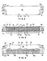
- Connection assembly 1 includes a male shielded electrical connector 10 and a mating female socket connector 12.
- Connectors 10 and 12 are designed for mating electrical connection, with male shielded connector 10 being insertable into female socket connector 12.
- Female socket connector 12 is a conventional multi-pin electrical connector including an elongate insulative housing 14 defining a central cavity 16 which accommodates in removable disposition male shielded connector 10.
- Housing 14 supports a plurality of electrical contact pins 18 having upper portions 18a extending into cavity 16 and opposed lower portions 18b extending exteriorly through housing 14.
- Housing 14 also supports a plurality of additional electrical contacts 20 along the interior sidewalls 14a thereof.
- Electrical contacts 20 are spring type contacts having upper spring portions 20a which extend into cavity 16.
- contact pins 18 are designed for electrical connection with mating contacts of male shielded connector 10 while electrical contacts 20 are designed for connection with the shielded portions of male shielded connector 10.
- Housing 14 further includes at the ends thereof, mounting apertures 22 which receive appropriate hardware (not shown) to secure male shielded connector 10 to female socket connector 12.
- Shielded connector 10 includes an elongate insulative housing 24 having a generally rectangular shape and structured to be accommodated in the cavity 16 of female socket connector 12. Housing 24 includes a connection surface 26 along one longitudinal side thereof and an attachment surface 28 (Fig. 4) along another longitudinal side thereof.
- connection surface 26 is disposed in a plane which is perpendicular to the plane containing attachment surface 28, to form what is known in the industry as a right-angle connector.
- attachment surface 28 is secured to a printed circuit board 30, shown in phantom in Figure 1.
- connection of male shielded connector 10 to female socket connector 12 is made in a direction parallel to the plane of the printed circuit board 30. It is, however, contemplated that the present invention may be practiced in a straight-through connector, that is, a connector having a connection surface and an attachment surface in spaced parallel orientation.
- Male shielded connector 10 further includes a plurality of electrical terminals 32 (Figs. 3 and 4) in like number to the number of contact pins 18 in female socket connector 12 for electrical connection therewith.
- Terminals 32 are of the right angle variety having a connection portion 34 disposed at a right-angle to a terminal tail 36.
- connection portion 34 of terminal 32 is formed into a conventional socket for electrical engagement with the contact pins 18 upon insertion of male shielded connector 10 into female socket connector 12.
- Connection portions 34 of terminals 32 are positioned along connection surface 26, to facilitate interconnection with contact pins 18.
- Terminal tails 36 extend beyond attachment surface 28 to make electrical interconnection with plated through-holes (not shown) of printed circuit board 30.
- male shielded connector 10 In order to positionally secure male shielded connector 10 to printed circuit board 30, male shielded connector 10 includes board mounting ears 38 extending from each transverse end thereof. As shown in more detail in Figures 2 and 4, board mounting ears 38 extend outwardly from housing 24 and include a central aperture 38a alignable with like apertures (not shown) on printed circuit board 30. A conventional nut and bolt assembly 40, shown more specifically in Figure 5, may be used to secure male shielded connector 10 to printed circuit board 30.
- Male shielded connector 10 further includes connector mounting ears 42 adjacent each of board mounting ears 38. Shown more specifically in Figure 3, connector mounting ears 42 include a central aperture 42a alignable with mounting apertures 22 of female socket connector 12 so that a fastening device (not shown) may be inserted therethrough to secure male shielded connector 10 to female socket connector 12.
- connector 10 In order to shield male shielded connector 10 from electromagnetic interferences (EMI) and radio frequency interferences (RFI), connector 10 includes shields 50 and 52 along housing 24.
- shields 50 and 52 is an elongate substantially planar member formed of an electrically conductive material, preferably metal.
- shield 50 is disposed on an upper longitudinal surface 44 of housing 24.
- Shield 50 includes a planar portion 51 partially coextensive with upper surface 44.
- a depending portion 54 extends downward toward each board mounting ear 38.
- Shield 50 further includes a projecting portion 56 which extends over an upper surface 37 of board mounting ear 38.
- An opening 56a is alignable with aperture 38a of mounting ear 38.
- lower shield 52 is positioned along attachment surface 28 of housing 24.
- Shield 52 includes a planar portion 57 which is partially coextensive with attachment surface 28, however, having a cutaway portion 52a permitting passage of terminal tails 36 therethrough.
- a pair of opposed lateral extents 58 extend over a lower surface 39 of board mounting ears 38.
- Each lateral extent 58 includes an opening 58a therethrough alignable with the aperture 38a of board mounting ears 38.
- Lateral extents 58 further include upstanding side portions 60 which extend upward toward upper shield 50.
- a distal end extent 62 extends at a right angle to side portion 60 over the projecting portion 56 of upper shield 50.
- An opening 62a in distal end extent 62 is alignable with opening 56a of projection portion 56 of shield 50 and also alignable with aperture 38a of mounting ear 38.
- the lateral extent 58, upstanding side portion 60 and distal end extent 62 actually wrap-around shield ear 38 and projecting portion 56 of shield 50, to partially enclose projecting portion 56 and shield ear 38.
- FIG. 5 providing a shield formed in such fashion permits nut and bolt assembly 40 not only to secure housing 14 to printed circuit board 30 but also to secure each of shield 50 and 52 to housing 14.
- mounting hardware normally associated with the securement of male shielded connector 10 to printed circuit board 30 may also be used to secure the metallic shields 50 and 52 to the connector housing 14. Any vibratory forces which may be encountered will not cause the shields 50 and 52 to be dislodged from housing 24, as the nut and bolt assembly 40 securing male connector 10 to printed circuit board 30 also secures the shields 50 and 52.
- shields 50 and 52 are additionally secured to housing 24 along the longitudinal edges thereof adjacent connection surface 26.
- Each of shields 50 and 52 includes plural inwardly projecting tabs 70 which project into housing 24.
- each of shields 50 and 52 includes four such tabs 70 spaced longitudinally thereacross which are punched from the planar portions 51 and 57 of the respective metallic shields 50 and 52.
- Housing 24 includes plural slots 72 (co-extensive with tabs 70 as shown in Fig. 3) adjacent connection surface 26 which receive each of tabs 70. The arrangement of the tabs 70 and the slots 72 serve to securely position each of shields 50 and 52 with respect to housing 24.
- the shield will remain securely in place with respect to housing 24.
Landscapes
- Details Of Connecting Devices For Male And Female Coupling (AREA)
- Coupling Device And Connection With Printed Circuit (AREA)
- Shielding Devices Or Components To Electric Or Magnetic Fields (AREA)
Applications Claiming Priority (2)
| Application Number | Priority Date | Filing Date | Title |
|---|---|---|---|
| US07/364,283 US4915652A (en) | 1989-06-12 | 1989-06-12 | Shielded electrical connector |
| US364283 | 1989-06-12 |
Publications (1)
| Publication Number | Publication Date |
|---|---|
| EP0403106A1 true EP0403106A1 (fr) | 1990-12-19 |
Family
ID=23433824
Family Applications (1)
| Application Number | Title | Priority Date | Filing Date |
|---|---|---|---|
| EP90305829A Ceased EP0403106A1 (fr) | 1989-06-12 | 1990-05-29 | Connecteur électrique blindé |
Country Status (5)
| Country | Link |
|---|---|
| US (1) | US4915652A (fr) |
| EP (1) | EP0403106A1 (fr) |
| JP (1) | JPH0628194B2 (fr) |
| AU (1) | AU616353B2 (fr) |
| CA (1) | CA2015756C (fr) |
Cited By (1)
| Publication number | Priority date | Publication date | Assignee | Title |
|---|---|---|---|---|
| EP1100161A3 (fr) * | 1999-11-09 | 2004-12-01 | Autonetworks Technologies, Ltd. | Méthode de traitement des terminaux et structure d'un cable blindé |
Families Citing this family (8)
| Publication number | Priority date | Publication date | Assignee | Title |
|---|---|---|---|---|
| PT97705A (pt) * | 1990-07-20 | 1993-07-30 | Ibm | Computador pessoal com blindagem de proteccao dos sinais de entrada/saida |
| US5617577A (en) * | 1990-11-13 | 1997-04-01 | International Business Machines Corporation | Advanced parallel array processor I/O connection |
| US5130896A (en) * | 1991-02-22 | 1992-07-14 | Hewlett-Packard Company | Apparatus for electromagnetic interference containment for printed circuit board connectors |
| US5588848A (en) * | 1994-09-08 | 1996-12-31 | Lucent Technologies Inc. | Low inductance surface-mount connectors for interconnecting circuit devices and method for using same |
| DE19508409C1 (de) * | 1995-03-09 | 1996-05-09 | Harting Elektronik Gmbh | Steckverbinder mit Befestigungsmitteln |
| JP4092071B2 (ja) * | 2000-11-30 | 2008-05-28 | 三菱電機株式会社 | 半導体パワーモジュール |
| EP2262062B1 (fr) * | 2009-05-27 | 2013-09-04 | PHOENIX CONTACT GmbH & Co. KG | Connecteur à fiches |
| JP5794292B2 (ja) * | 2013-12-27 | 2015-10-14 | 第一精工株式会社 | 電気コネクタ |
Citations (2)
| Publication number | Priority date | Publication date | Assignee | Title |
|---|---|---|---|---|
| EP0189288A2 (fr) * | 1985-01-18 | 1986-07-30 | E.I. Du Pont De Nemours And Company | Connecteur blindé et assemblage |
| WO1988007776A1 (fr) * | 1987-03-27 | 1988-10-06 | Amp Incorporated | Systeme de retenue et d'alignement de broches de brasage |
Family Cites Families (19)
| Publication number | Priority date | Publication date | Assignee | Title |
|---|---|---|---|---|
| US32502A (en) * | 1861-06-11 | Combined thresher and separator | ||
| US3329925A (en) * | 1965-07-29 | 1967-07-04 | Leeds & Northrup Co | Interlocking shielded connector |
| US4195198A (en) * | 1979-01-08 | 1980-03-25 | General Electric Company | Busway ground bus joint |
| US4272148A (en) * | 1979-04-05 | 1981-06-09 | Hewlett-Packard Company | Shielded connector housing for use with a multiconductor shielded cable |
| US4337989A (en) * | 1980-05-28 | 1982-07-06 | Amp Incorporated | Electromagnetic shielded connector |
| US4386814A (en) * | 1981-08-17 | 1983-06-07 | Amp Incorporated | Kit for converting a panel opening to a shielded pin receptacle |
| US4512618A (en) * | 1983-03-10 | 1985-04-23 | Amp Incorporated | Grounding mating hardware |
| USRE32502E (en) | 1983-03-10 | 1987-09-15 | Amp Incorporated | Grounding mating hardware |
| US4687263A (en) * | 1983-03-10 | 1987-08-18 | Amp Incorporated | Shielding kit for electrical connectors terminating multiconductor 360 degree shielded cable |
| JPS59166382U (ja) * | 1983-04-25 | 1984-11-07 | 第一電子工業株式会社 | シ−ルドコネクタ |
| US4506937A (en) * | 1983-05-02 | 1985-03-26 | Amp Incorporated | Latching-grounding blocks |
| US4518209A (en) * | 1983-06-30 | 1985-05-21 | Welcon Connector Company | Connector block with RF shield |
| US4521062A (en) * | 1983-07-26 | 1985-06-04 | International Telephone And Telegraph Corporation | Electrical connector with optional grounding element |
| US4655518A (en) * | 1984-08-17 | 1987-04-07 | Teradyne, Inc. | Backplane connector |
| BR8505361A (pt) * | 1984-10-29 | 1986-08-05 | Du Pont | Blindagem inteirica de conecto de painel de circuito impresso |
| US4690479A (en) * | 1985-10-10 | 1987-09-01 | Amp Incorporated | Filtered electrical header assembly |
| US4679883A (en) * | 1986-09-08 | 1987-07-14 | Amp Incorporated | Shoulder eyelet board lock |
| US4689723A (en) * | 1986-09-29 | 1987-08-25 | Amp Incorporated | Hermaphroditic shield for line terminator |
| US4799901A (en) * | 1988-06-30 | 1989-01-24 | Pirc Douglas J | Adapter having transient suppression protection |
-
1989
- 1989-06-12 US US07/364,283 patent/US4915652A/en not_active Expired - Lifetime
-
1990
- 1990-04-30 CA CA002015756A patent/CA2015756C/fr not_active Expired - Fee Related
- 1990-05-02 AU AU54592/90A patent/AU616353B2/en not_active Ceased
- 1990-05-29 EP EP90305829A patent/EP0403106A1/fr not_active Ceased
- 1990-06-12 JP JP2151761A patent/JPH0628194B2/ja not_active Expired - Lifetime
Patent Citations (2)
| Publication number | Priority date | Publication date | Assignee | Title |
|---|---|---|---|---|
| EP0189288A2 (fr) * | 1985-01-18 | 1986-07-30 | E.I. Du Pont De Nemours And Company | Connecteur blindé et assemblage |
| WO1988007776A1 (fr) * | 1987-03-27 | 1988-10-06 | Amp Incorporated | Systeme de retenue et d'alignement de broches de brasage |
Cited By (1)
| Publication number | Priority date | Publication date | Assignee | Title |
|---|---|---|---|---|
| EP1100161A3 (fr) * | 1999-11-09 | 2004-12-01 | Autonetworks Technologies, Ltd. | Méthode de traitement des terminaux et structure d'un cable blindé |
Also Published As
| Publication number | Publication date |
|---|---|
| US4915652A (en) | 1990-04-10 |
| JPH0628194B2 (ja) | 1994-04-13 |
| CA2015756C (fr) | 1993-11-09 |
| JPH0362467A (ja) | 1991-03-18 |
| CA2015756A1 (fr) | 1990-12-12 |
| AU616353B2 (en) | 1991-10-24 |
| AU5459290A (en) | 1991-02-07 |
Similar Documents
| Publication | Publication Date | Title |
|---|---|---|
| EP0188876B1 (fr) | Agencement d'un connecteur électrique blindé | |
| US5478259A (en) | Card edge connector with combined shielding and voltage drain protection | |
| EP0600120B1 (fr) | Système de connecteur électrique à fiche et prise | |
| US5697799A (en) | Board-mountable shielded electrical connector | |
| US5244415A (en) | Shielded electrical connector and cable | |
| US7892007B2 (en) | Electrical connector assembly | |
| US5163851A (en) | Connector with formed wire boardlock and boardlock therefor | |
| EP0459356A2 (fr) | Connecteur écranné de bords à doubles niveaux pour plaquette à circuits imprimés | |
| EP0393864A1 (fr) | Connecteur électrique et support de fixation pour le connecteur | |
| EP0333386A1 (fr) | Connecteur électrique blindé pour montage sur circuit imprimé | |
| EP0002890A1 (fr) | Connecteur électrique blindé | |
| EP0624928B1 (fr) | Ensemble connecteur électrique blindé | |
| KR101121836B1 (ko) | 커넥터 장치 | |
| EP0707359A2 (fr) | Connecteur electrique pour montage en surface sur une plaquette à circuits imprimés | |
| US6361332B1 (en) | Retention system for electrical connectors | |
| US5820393A (en) | Board mounted electrical connector with multi-function board lock | |
| EP0729203A2 (fr) | Connecteur électrique blindé | |
| US4915652A (en) | Shielded electrical connector | |
| US5307242A (en) | Device for electrically connecting shieldings of multi-pole plugs to the ground layer of a wiring board | |
| US4880397A (en) | Filtered cable harness connector assembly | |
| EP1126552A2 (fr) | Connecteur de circuit imprimé avec fourche de retenue | |
| EP0774807A2 (fr) | Connecteur électrique | |
| EP0507166B1 (fr) | Connecteur électrique de mise à la terre | |
| US6210228B1 (en) | Shielded electrical connector | |
| JPH09245861A (ja) | 電気コネクタ |
Legal Events
| Date | Code | Title | Description |
|---|---|---|---|
| PUAI | Public reference made under article 153(3) epc to a published international application that has entered the european phase |
Free format text: ORIGINAL CODE: 0009012 |
|
| AK | Designated contracting states |
Kind code of ref document: A1 Designated state(s): BE CH DE ES FR GB IT LI LU NL SE |
|
| 17P | Request for examination filed |
Effective date: 19901220 |
|
| 17Q | First examination report despatched |
Effective date: 19930212 |
|
| STAA | Information on the status of an ep patent application or granted ep patent |
Free format text: STATUS: THE APPLICATION HAS BEEN REFUSED |
|
| RAP3 | Party data changed (applicant data changed or rights of an application transferred) |
Owner name: THOMAS & BETTS CORPORATION |
|
| 18R | Application refused |
Effective date: 19940131 |