EP0189494A1 - Rundmessereinheit mit Spannvorrichtung zum Streifenscheren - Google Patents
Rundmessereinheit mit Spannvorrichtung zum Streifenscheren Download PDFInfo
- Publication number
- EP0189494A1 EP0189494A1 EP85100841A EP85100841A EP0189494A1 EP 0189494 A1 EP0189494 A1 EP 0189494A1 EP 85100841 A EP85100841 A EP 85100841A EP 85100841 A EP85100841 A EP 85100841A EP 0189494 A1 EP0189494 A1 EP 0189494A1
- Authority
- EP
- European Patent Office
- Prior art keywords
- piston
- pressure chamber
- threaded shaft
- pusher
- communicated
- Prior art date
- Legal status (The legal status is an assumption and is not a legal conclusion. Google has not performed a legal analysis and makes no representation as to the accuracy of the status listed.)
- Granted
Links
- 229910000831 Steel Inorganic materials 0.000 claims description 10
- 239000010959 steel Substances 0.000 claims description 10
- 125000006850 spacer group Chemical group 0.000 description 16
Images




Classifications
-
- B—PERFORMING OPERATIONS; TRANSPORTING
- B26—HAND CUTTING TOOLS; CUTTING; SEVERING
- B26D—CUTTING; DETAILS COMMON TO MACHINES FOR PERFORATING, PUNCHING, CUTTING-OUT, STAMPING-OUT OR SEVERING
- B26D7/00—Details of apparatus for cutting, cutting-out, stamping-out, punching, perforating, or severing by means other than cutting
- B26D7/26—Means for mounting or adjusting the cutting member; Means for adjusting the stroke of the cutting member
- B26D7/2614—Means for mounting the cutting member
- B26D7/2621—Means for mounting the cutting member for circular cutters
-
- B—PERFORMING OPERATIONS; TRANSPORTING
- B23—MACHINE TOOLS; METAL-WORKING NOT OTHERWISE PROVIDED FOR
- B23Q—DETAILS, COMPONENTS, OR ACCESSORIES FOR MACHINE TOOLS, e.g. ARRANGEMENTS FOR COPYING OR CONTROLLING; MACHINE TOOLS IN GENERAL CHARACTERISED BY THE CONSTRUCTION OF PARTICULAR DETAILS OR COMPONENTS; COMBINATIONS OR ASSOCIATIONS OF METAL-WORKING MACHINES, NOT DIRECTED TO A PARTICULAR RESULT
- B23Q3/00—Devices holding, supporting, or positioning work or tools, of a kind normally removable from the machine
- B23Q3/02—Devices holding, supporting, or positioning work or tools, of a kind normally removable from the machine for mounting on a work-table, tool-slide, or analogous part
- B23Q3/06—Work-clamping means
- B23Q3/08—Work-clamping means other than mechanically-actuated
-
- Y—GENERAL TAGGING OF NEW TECHNOLOGICAL DEVELOPMENTS; GENERAL TAGGING OF CROSS-SECTIONAL TECHNOLOGIES SPANNING OVER SEVERAL SECTIONS OF THE IPC; TECHNICAL SUBJECTS COVERED BY FORMER USPC CROSS-REFERENCE ART COLLECTIONS [XRACs] AND DIGESTS
- Y10—TECHNICAL SUBJECTS COVERED BY FORMER USPC
- Y10T—TECHNICAL SUBJECTS COVERED BY FORMER US CLASSIFICATION
- Y10T83/00—Cutting
- Y10T83/768—Rotatable disc tool pair or tool and carrier
- Y10T83/7809—Tool pair comprises rotatable tools
- Y10T83/783—Tool pair comprises contacting overlapped discs
- Y10T83/7834—With means to effect axial pressure on pair
- Y10T83/7838—With means to change axial pressure
-
- Y—GENERAL TAGGING OF NEW TECHNOLOGICAL DEVELOPMENTS; GENERAL TAGGING OF CROSS-SECTIONAL TECHNOLOGIES SPANNING OVER SEVERAL SECTIONS OF THE IPC; TECHNICAL SUBJECTS COVERED BY FORMER USPC CROSS-REFERENCE ART COLLECTIONS [XRACs] AND DIGESTS
- Y10—TECHNICAL SUBJECTS COVERED BY FORMER USPC
- Y10T—TECHNICAL SUBJECTS COVERED BY FORMER US CLASSIFICATION
- Y10T83/00—Cutting
- Y10T83/929—Tool or tool with support
- Y10T83/9372—Rotatable type
- Y10T83/9374—With spacer interposed between shaft-mounted tools
-
- Y—GENERAL TAGGING OF NEW TECHNOLOGICAL DEVELOPMENTS; GENERAL TAGGING OF CROSS-SECTIONAL TECHNOLOGIES SPANNING OVER SEVERAL SECTIONS OF THE IPC; TECHNICAL SUBJECTS COVERED BY FORMER USPC CROSS-REFERENCE ART COLLECTIONS [XRACs] AND DIGESTS
- Y10—TECHNICAL SUBJECTS COVERED BY FORMER USPC
- Y10T—TECHNICAL SUBJECTS COVERED BY FORMER US CLASSIFICATION
- Y10T83/00—Cutting
- Y10T83/929—Tool or tool with support
- Y10T83/9457—Joint or connection
- Y10T83/9464—For rotary tool
- Y10T83/9469—Adjustable
- Y10T83/9471—Rectilinearly
Definitions
- the present invention relates to a pusher for pushing an object such as parts or a work or a tool respectively of a machine uniformly.
- a conventional steel plate slitter to cut a wide band steel plate into a plurality of narrow band steel plates as shown in Fig. 1, two arbors 21, 22, are arranged in parallel on the vertical plane and each of the arbors 21, 22 is provided with a slipping-proof part 23 of large diameter at one end and a threaded part 24 of small diameter at other end.
- Annular or cylindrical spacers 25 and annular plate form cutters 26 are fitted to each of the arbors 21, 22 and a nut 27 threadably engaged with the threaded part 24 of each of the arbors 21, 22 is tightened, so that a plurality of the spacers 25 and a plurality of the cutters 26 are grasped between the nut 27 and slipping-proof part 23 of each of the arbors 21, 22 and a plurality of the cutters 26 are mounted on required positions of each of the arbors 21, 22 and bottom end of each cutter 26 of the arbor 21 on upper side and top end of each cutter 26 of the arbor 22 on lower side are spaced by a required gap.
- an object of the invention is to provide a pusher which can easily push such an object as parts and a work of a machine uniformly with large force.
- the invention provides for a pusher comprising a body, in which a plurality of piston holes are formed in a front surface of a body, pistons each being slidably fitted into the piston holes and the front end of each piston extends in front of said body, the body is provided with an oil passage provided in said body and communicated with a bottom portion of each of said piston holes, a pressure chamber provided in said body and communicated with said oil passage, a threaded shaft threadably fitted to a threaded hole.
- each piston is supported by oil in the oil passage communicated with the bottom of each piston hole, even if a piston abutting surface of an object which abuts on the front end of each piston extending in front of the body is slanted or uneven, the pistons move forwardly or rearwardly and the position of each piston abutting on the object is adjusted whereby each piston abuts on the object uniformly so as to push the object uniformly.
- the piston is pushed by a force larger than the advancing force of the threaded shaft and therefore it is easy to increase the pushing force of the piston.
- the pusher of the invention using the pistons can easily push the object uniformly by a large force.
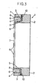
- a pusher 1 of the embodiment as clearly seen in Fig. 2 and Fig. 3, comprises an annular body 2, and a number of piston holes 3 bored from a front surface of the body 2 at equally spaced positions along the axial direction of the body 2.
- a piston 4 is slidably fitted with an 0-ring 5 fitted to a circumferential groove on a circumferential surface thereof.
- An annular cover plate 7 provided with piston holes 8 of small diameter is overlaid on the front surface of the body 2 and fixed by a number of bolts 9.
- Each of the piston holes 8 of the cover plate 7 is in alignment with each piston hole 3 of the body 2.
- a front end portion 6 with small diameter of each piston 4 is inserted in the piston hole 8 of the cover plate 7, and a front end surface of spherical form of each piston 4 extends in front of the cover plate 7 (Fig.6).
- An annular oil passage 10 communicated with a bottom portion of each piston hole 3 is formed within the body 2.
- holes 11 are bored at two positions on outer circumferential surface of the body 2, and part of each hole 11 at bottom side is formed as a pressure chamber 12 and part of each hole 11 at opening side is formed as a threaded hole 13.
- each pressure chamber 12 A bottom portion of each pressure chamber 12 is communicated with the oil passage 10 through a small hole 14, and a piston 15 with an 0-ring 16 fitted to a circumferential groove on a circumferential surface thereof is slidably fitted in each pressure chamber 12.
- a threaded shaft 17 is threadably fitted to each threaded hole 13, and a top end surface of spherical form of each threaded shaft 17 abuts on a base end surface of each piston 15.
- a stopper 19, as clearly seen in Fig. 4 and Fig. 5, is fixed to opening position of each threaded hole 13 using a bolt 20, and a base end surface with a hexagonal hole 18 of the threaded shaft 17 abuts on the stopper 19.
- Total cross-sectional area of all piston holes 3 is set to about 20 times as large as cross-sectional area of each pressure chamber 12, and oil is filled in the bottom portion of each piston hole 3, the oil passage 10, each small hole 14 and each pressure chamber 12. If any of the threaded shafts 17 is threadably advanced towards the pressure chamber 12 and the piston 15 is pushed by the threaded shaft 17 to bottom side of the pressure chamber 12, the piston 4 on the front surface of the body 2 is pushed forwards through the oil pressure by force of about 20 times as large as the advancing force of the threaded shaft 17 or the piston 15, respectively.
- each piston 4 on the front surface of the pusher 1 is pushed forwards thereby urging the spacers 29, 25, 28, and the cutters 26, and each cutter 26 grasped between the spacers 25, 25 or between the spacers 25, 29 is pushed from both sides and tightened.
- each piston 4 applies pressure to the oil in the oil passage 10 and the oil opposes against the pressure by reaction force being uniform in all directions.
- the piston abutting surface of the spacers 29 or the cutter abutting surface of the spacer 25, 29 is not perpendicular to the arbor axial direction but slanted and therefore the pushing force of each piston 4 is different, the pistons 4 move forwards or rearwards and the position of each piston 4 abutting on the spacer 29 is adjusted, and all of the pistons 4 opposed by the oil at the uniform reaction force abut on the piston abutting surface of the spacer 29 uniformly, thereby thightening the cutter 26 by uniform force directed exactly perpendicular to the arbors 21, 22.
- the pusher 1 of the embodiment can be used not only in the above case to tighten the cutter 26 of the steel plate slitter, parts of a machine, but also in other various cases, so that an object such as a work for a machine tool abutting on the front end of each piston 4 can be easily pushed uniformly at large force.
Landscapes
- Engineering & Computer Science (AREA)
- Mechanical Engineering (AREA)
- Life Sciences & Earth Sciences (AREA)
- Forests & Forestry (AREA)
- Shearing Machines (AREA)
Priority Applications (4)
| Application Number | Priority Date | Filing Date | Title |
|---|---|---|---|
| DE8585100841T DE3570056D1 (en) | 1985-01-28 | 1985-01-28 | A slitting cutter assembly with tightening device |
| EP85100841A EP0189494B1 (de) | 1985-01-28 | 1985-01-28 | Rundmessereinheit mit Spannvorrichtung zum Streifenscheren |
| US06/928,687 US4781095A (en) | 1985-01-28 | 1986-11-07 | Pusher |
| SG822/89A SG82289G (en) | 1985-01-28 | 1989-12-21 | A slitting cutter assembly with tightening device |
Applications Claiming Priority (1)
| Application Number | Priority Date | Filing Date | Title |
|---|---|---|---|
| EP85100841A EP0189494B1 (de) | 1985-01-28 | 1985-01-28 | Rundmessereinheit mit Spannvorrichtung zum Streifenscheren |
Publications (2)
| Publication Number | Publication Date |
|---|---|
| EP0189494A1 true EP0189494A1 (de) | 1986-08-06 |
| EP0189494B1 EP0189494B1 (de) | 1989-05-10 |
Family
ID=8193257
Family Applications (1)
| Application Number | Title | Priority Date | Filing Date |
|---|---|---|---|
| EP85100841A Expired EP0189494B1 (de) | 1985-01-28 | 1985-01-28 | Rundmessereinheit mit Spannvorrichtung zum Streifenscheren |
Country Status (4)
| Country | Link |
|---|---|
| US (1) | US4781095A (de) |
| EP (1) | EP0189494B1 (de) |
| DE (1) | DE3570056D1 (de) |
| SG (1) | SG82289G (de) |
Cited By (2)
| Publication number | Priority date | Publication date | Assignee | Title |
|---|---|---|---|---|
| DE102008024361A1 (de) * | 2008-05-20 | 2009-11-26 | Dienes Werke für Maschinenteile GmbH & Co KG | Messerträger mit abschaltbarer Befederung |
| DE102008024362A1 (de) * | 2008-05-20 | 2009-11-26 | Dienes Werke für Maschinenteile GmbH & Co KG | Messerträger mit variabel einstellbarer Vorspannung des Kreismessers |
Families Citing this family (3)
| Publication number | Priority date | Publication date | Assignee | Title |
|---|---|---|---|---|
| US4922778A (en) * | 1987-10-16 | 1990-05-08 | Sky Aluminum Co., Ltd. | Apparatus for cutting metal sheet |
| DE19526507C2 (de) * | 1995-07-20 | 1999-04-08 | Wifag Maschf | Messerzylinder mit verstellbarem Messerbalken |
| US6308601B1 (en) * | 1998-11-19 | 2001-10-30 | Eastman Kodak Company | Apparatus and method for slitting a sheet of web material |
Citations (4)
| Publication number | Priority date | Publication date | Assignee | Title |
|---|---|---|---|---|
| DE1842788U (de) * | 1961-10-11 | 1961-11-30 | Rolf Diehl | Spannvorrichtung mit hydraulischer kraftuebertragung. |
| DE1884821U (de) * | 1963-10-04 | 1963-12-19 | Albert Schrem Werkzeugfabrik | Zwischenstueck fuer spannvorrichtungen an werkzeugmaschinen. |
| DE2552873A1 (de) * | 1975-11-25 | 1977-05-26 | Schrem Kg Albert | Hydraulisches spannelement |
| US4220064A (en) * | 1979-02-21 | 1980-09-02 | Paxson Machine Company | Clamping device |
Family Cites Families (12)
| Publication number | Priority date | Publication date | Assignee | Title |
|---|---|---|---|---|
| US154366A (en) * | 1874-08-25 | Improvement in hydraulic jacks | ||
| US966750A (en) * | 1909-10-16 | 1910-08-09 | James B Hunt | Steering device. |
| US1367857A (en) * | 1920-02-26 | 1921-02-08 | William J Hold | Lifting-jack |
| US2240287A (en) * | 1940-01-05 | 1941-04-29 | Joseph Sackel | Radio apparatus tuning device |
| US2344473A (en) * | 1942-10-05 | 1944-03-14 | Merit Engineering Inc | Remote control apparatus |
| DE1267944B (de) * | 1963-02-12 | 1968-05-09 | Albert Schrem Fa | Hydraulisches Spannelement, insbesondere zum Spannen von Fraesern auf einem Fraesdorn |
| US3213625A (en) * | 1964-06-04 | 1965-10-26 | Fed Products Corp | Precision adjusting apparatus |
| US3357182A (en) * | 1965-10-23 | 1967-12-12 | Gen Motors Corp | Screw type master cylinder assembly |
| DE1759429C3 (de) * | 1968-04-30 | 1973-12-20 | Villeroy & Boch Keramische Werke Kg, 6642 Mettlach | Vorrichtung zum gleichzeitigen Pressen mehrerer plattenförmiger Presslinge |
| US3769794A (en) * | 1970-03-31 | 1973-11-06 | Ibm | Manipulation apparatus |
| US4373334A (en) * | 1979-09-26 | 1983-02-15 | Carlander Lars Erik | Device for variable height adjustment of supports |
| JPS59153162A (ja) * | 1983-02-21 | 1984-09-01 | Narumo Kagaku Kikai Kenkyusho:Kk | 硝子電極等の微動操作器械 |
-
1985
- 1985-01-28 EP EP85100841A patent/EP0189494B1/de not_active Expired
- 1985-01-28 DE DE8585100841T patent/DE3570056D1/de not_active Expired
-
1986
- 1986-11-07 US US06/928,687 patent/US4781095A/en not_active Expired - Lifetime
-
1989
- 1989-12-21 SG SG822/89A patent/SG82289G/en unknown
Patent Citations (4)
| Publication number | Priority date | Publication date | Assignee | Title |
|---|---|---|---|---|
| DE1842788U (de) * | 1961-10-11 | 1961-11-30 | Rolf Diehl | Spannvorrichtung mit hydraulischer kraftuebertragung. |
| DE1884821U (de) * | 1963-10-04 | 1963-12-19 | Albert Schrem Werkzeugfabrik | Zwischenstueck fuer spannvorrichtungen an werkzeugmaschinen. |
| DE2552873A1 (de) * | 1975-11-25 | 1977-05-26 | Schrem Kg Albert | Hydraulisches spannelement |
| US4220064A (en) * | 1979-02-21 | 1980-09-02 | Paxson Machine Company | Clamping device |
Non-Patent Citations (1)
| Title |
|---|
| PATENT ABSTRACTS OF JAPAN, vol. 6, no. 207 (M-165)[1085], 19th October 1982; & JP - A - 57 114 315 (KAWASAKI SEITETSU K.K.) 16-07-1982 * |
Cited By (2)
| Publication number | Priority date | Publication date | Assignee | Title |
|---|---|---|---|---|
| DE102008024361A1 (de) * | 2008-05-20 | 2009-11-26 | Dienes Werke für Maschinenteile GmbH & Co KG | Messerträger mit abschaltbarer Befederung |
| DE102008024362A1 (de) * | 2008-05-20 | 2009-11-26 | Dienes Werke für Maschinenteile GmbH & Co KG | Messerträger mit variabel einstellbarer Vorspannung des Kreismessers |
Also Published As
| Publication number | Publication date |
|---|---|
| EP0189494B1 (de) | 1989-05-10 |
| DE3570056D1 (en) | 1989-06-15 |
| US4781095A (en) | 1988-11-01 |
| SG82289G (en) | 1990-08-03 |
Similar Documents
| Publication | Publication Date | Title |
|---|---|---|
| US5437524A (en) | Torque-adjustment controller | |
| DE69601566T2 (de) | Werkzeugsystem mit austauschbarem Adaptor | |
| EP1849583B1 (de) | Vorrichtung zum Bearbeiten von Werkstücken mittels Ultraschall | |
| EP0614716B1 (de) | Spannfutter zur Bearbeitung von gerillten Werkstücken | |
| GB1597240A (en) | Clamping arrangement | |
| KR20030051327A (ko) | 파이프 단부의 마감가공용 공구 | |
| US5303754A (en) | Fastening system for a rip-saw blade and a chipping edger | |
| US5520491A (en) | Drill screw | |
| AU746476B2 (en) | Knife supporting structure | |
| US4403417A (en) | Draw punch | |
| EP1340559B1 (de) | Stanzvorrichtung mit Lochpositionsbestimmung | |
| EP0189494A1 (de) | Rundmessereinheit mit Spannvorrichtung zum Streifenscheren | |
| EP0488361B1 (de) | Werkzeughaltvorrichtung | |
| US7059216B2 (en) | Fastener removal apparatus | |
| JPS59142016A (ja) | 押圧盤 | |
| US5791661A (en) | Compliant chuck jaws | |
| MXPA05001931A (es) | Herramienta portdora para troquel cortador, con elementos de ajuste fino. | |
| DE3333385C2 (de) | Kopfschraube | |
| US4257462A (en) | Tool fastening system for woodworking machines or the like | |
| EP0494864B1 (de) | Rohrenbearbeitungswerkzeug mit verbesserung des torsionsverhaltens und der spannmoeglichkeiten | |
| US4770075A (en) | Cutting-off tool | |
| JP2959227B2 (ja) | ナットの解除方法 | |
| JP2514621Y2 (ja) | 油圧固定ナット | |
| JPH0655320A (ja) | 複合ツール | |
| JPS63102815A (ja) | カウンタボ−リングヘツド |
Legal Events
| Date | Code | Title | Description |
|---|---|---|---|
| PUAI | Public reference made under article 153(3) epc to a published international application that has entered the european phase |
Free format text: ORIGINAL CODE: 0009012 |
|
| AK | Designated contracting states |
Kind code of ref document: A1 Designated state(s): BE CH DE FR GB IT LI NL SE |
|
| 17P | Request for examination filed |
Effective date: 19870130 |
|
| 17Q | First examination report despatched |
Effective date: 19880411 |
|
| GRAA | (expected) grant |
Free format text: ORIGINAL CODE: 0009210 |
|
| AK | Designated contracting states |
Kind code of ref document: B1 Designated state(s): BE CH DE FR GB IT LI NL SE |
|
| ITF | It: translation for a ep patent filed | ||
| REF | Corresponds to: |
Ref document number: 3570056 Country of ref document: DE Date of ref document: 19890615 |
|
| ET | Fr: translation filed | ||
| PLBE | No opposition filed within time limit |
Free format text: ORIGINAL CODE: 0009261 |
|
| STAA | Information on the status of an ep patent application or granted ep patent |
Free format text: STATUS: NO OPPOSITION FILED WITHIN TIME LIMIT |
|
| 26N | No opposition filed | ||
| ITTA | It: last paid annual fee | ||
| EAL | Se: european patent in force in sweden |
Ref document number: 85100841.7 |
|
| PGFP | Annual fee paid to national office [announced via postgrant information from national office to epo] |
Ref country code: SE Payment date: 20010105 Year of fee payment: 17 |
|
| PGFP | Annual fee paid to national office [announced via postgrant information from national office to epo] |
Ref country code: DE Payment date: 20010122 Year of fee payment: 17 |
|
| PGFP | Annual fee paid to national office [announced via postgrant information from national office to epo] |
Ref country code: FR Payment date: 20010125 Year of fee payment: 17 |
|
| PGFP | Annual fee paid to national office [announced via postgrant information from national office to epo] |
Ref country code: NL Payment date: 20010131 Year of fee payment: 17 |
|
| PGFP | Annual fee paid to national office [announced via postgrant information from national office to epo] |
Ref country code: CH Payment date: 20010219 Year of fee payment: 17 |
|
| PGFP | Annual fee paid to national office [announced via postgrant information from national office to epo] |
Ref country code: BE Payment date: 20010313 Year of fee payment: 17 |
|
| REG | Reference to a national code |
Ref country code: GB Ref legal event code: IF02 |
|
| PG25 | Lapsed in a contracting state [announced via postgrant information from national office to epo] |
Ref country code: SE Free format text: LAPSE BECAUSE OF NON-PAYMENT OF DUE FEES Effective date: 20020129 |
|
| PG25 | Lapsed in a contracting state [announced via postgrant information from national office to epo] |
Ref country code: LI Free format text: LAPSE BECAUSE OF NON-PAYMENT OF DUE FEES Effective date: 20020131 Ref country code: CH Free format text: LAPSE BECAUSE OF NON-PAYMENT OF DUE FEES Effective date: 20020131 Ref country code: BE Free format text: LAPSE BECAUSE OF NON-PAYMENT OF DUE FEES Effective date: 20020131 |
|
| BERE | Be: lapsed |
Owner name: K.K. YOSHIDA SHOKAI Effective date: 20020131 |
|
| PG25 | Lapsed in a contracting state [announced via postgrant information from national office to epo] |
Ref country code: NL Free format text: LAPSE BECAUSE OF NON-PAYMENT OF DUE FEES Effective date: 20020801 Ref country code: DE Free format text: LAPSE BECAUSE OF NON-PAYMENT OF DUE FEES Effective date: 20020801 |
|
| EUG | Se: european patent has lapsed |
Ref document number: 85100841.7 |
|
| REG | Reference to a national code |
Ref country code: CH Ref legal event code: PL |
|
| PG25 | Lapsed in a contracting state [announced via postgrant information from national office to epo] |
Ref country code: FR Free format text: LAPSE BECAUSE OF NON-PAYMENT OF DUE FEES Effective date: 20020930 |
|
| NLV4 | Nl: lapsed or anulled due to non-payment of the annual fee |
Effective date: 20020801 |
|
| REG | Reference to a national code |
Ref country code: FR Ref legal event code: ST |
|
| PGFP | Annual fee paid to national office [announced via postgrant information from national office to epo] |
Ref country code: GB Payment date: 20040128 Year of fee payment: 20 |
|
| PG25 | Lapsed in a contracting state [announced via postgrant information from national office to epo] |
Ref country code: GB Free format text: LAPSE BECAUSE OF EXPIRATION OF PROTECTION Effective date: 20050127 |
|
| REG | Reference to a national code |
Ref country code: GB Ref legal event code: PE20 |