EP0189509A1 - Support de moteur - Google Patents
Support de moteur Download PDFInfo
- Publication number
- EP0189509A1 EP0189509A1 EP85105103A EP85105103A EP0189509A1 EP 0189509 A1 EP0189509 A1 EP 0189509A1 EP 85105103 A EP85105103 A EP 85105103A EP 85105103 A EP85105103 A EP 85105103A EP 0189509 A1 EP0189509 A1 EP 0189509A1
- Authority
- EP
- European Patent Office
- Prior art keywords
- ring
- disc
- filled
- gas
- suspended
- Prior art date
- Legal status (The legal status is an assumption and is not a legal conclusion. Google has not performed a legal analysis and makes no representation as to the accuracy of the status listed.)
- Granted
Links
- 239000012528 membrane Substances 0.000 claims abstract description 17
- 239000006096 absorbing agent Substances 0.000 claims abstract description 13
- 238000013016 damping Methods 0.000 claims abstract description 7
- 239000000725 suspension Substances 0.000 claims abstract description 7
- 239000007788 liquid Substances 0.000 claims abstract description 4
- 238000005192 partition Methods 0.000 abstract description 6
- 230000000694 effects Effects 0.000 description 3
- 238000002955 isolation Methods 0.000 description 2
- 230000002528 anti-freeze Effects 0.000 description 1
- 239000011324 bead Substances 0.000 description 1
- 239000012858 resilient material Substances 0.000 description 1
- XLYOFNOQVPJJNP-UHFFFAOYSA-N water Substances O XLYOFNOQVPJJNP-UHFFFAOYSA-N 0.000 description 1
Images
Classifications
-
- F—MECHANICAL ENGINEERING; LIGHTING; HEATING; WEAPONS; BLASTING
- F16—ENGINEERING ELEMENTS AND UNITS; GENERAL MEASURES FOR PRODUCING AND MAINTAINING EFFECTIVE FUNCTIONING OF MACHINES OR INSTALLATIONS; THERMAL INSULATION IN GENERAL
- F16F—SPRINGS; SHOCK-ABSORBERS; MEANS FOR DAMPING VIBRATION
- F16F13/00—Units comprising springs of the non-fluid type as well as vibration-dampers, shock-absorbers, or fluid springs
- F16F13/04—Units comprising springs of the non-fluid type as well as vibration-dampers, shock-absorbers, or fluid springs comprising both a plastics spring and a damper, e.g. a friction damper
- F16F13/06—Units comprising springs of the non-fluid type as well as vibration-dampers, shock-absorbers, or fluid springs comprising both a plastics spring and a damper, e.g. a friction damper the damper being a fluid damper, e.g. the plastics spring not forming a part of the wall of the fluid chamber of the damper
- F16F13/22—Units comprising springs of the non-fluid type as well as vibration-dampers, shock-absorbers, or fluid springs comprising both a plastics spring and a damper, e.g. a friction damper the damper being a fluid damper, e.g. the plastics spring not forming a part of the wall of the fluid chamber of the damper characterised by comprising also a dynamic damper
-
- F—MECHANICAL ENGINEERING; LIGHTING; HEATING; WEAPONS; BLASTING
- F16—ENGINEERING ELEMENTS AND UNITS; GENERAL MEASURES FOR PRODUCING AND MAINTAINING EFFECTIVE FUNCTIONING OF MACHINES OR INSTALLATIONS; THERMAL INSULATION IN GENERAL
- F16F—SPRINGS; SHOCK-ABSORBERS; MEANS FOR DAMPING VIBRATION
- F16F13/00—Units comprising springs of the non-fluid type as well as vibration-dampers, shock-absorbers, or fluid springs
- F16F13/04—Units comprising springs of the non-fluid type as well as vibration-dampers, shock-absorbers, or fluid springs comprising both a plastics spring and a damper, e.g. a friction damper
- F16F13/06—Units comprising springs of the non-fluid type as well as vibration-dampers, shock-absorbers, or fluid springs comprising both a plastics spring and a damper, e.g. a friction damper the damper being a fluid damper, e.g. the plastics spring not forming a part of the wall of the fluid chamber of the damper
- F16F13/20—Units comprising springs of the non-fluid type as well as vibration-dampers, shock-absorbers, or fluid springs comprising both a plastics spring and a damper, e.g. a friction damper the damper being a fluid damper, e.g. the plastics spring not forming a part of the wall of the fluid chamber of the damper characterised by comprising also a pneumatic spring
Definitions
- the invention relates to a motor mount with hydraulic damping, comprising a working space delimited by a support, a suspension spring and a dividing wall and an equalizing space delimited by the dividing wall and a flexible buffer wall, which are connected by a throttle opening and filled with a liquid, and one arranged in the dividing wall , gas-filled chamber facing the work space is closed off by a circularly delimited first disc suspended from an elastic ring membrane.
- European patent application 0 115 417 refers to an engine mount of the aforementioned type.
- the elastically suspended disc is rigid in itself and is arranged between stops on both sides in order to achieve good damping of low-frequency vibrations and good isolation of high-frequency vibrations.
- both types of vibrations usually occur in a combined form in an engine mount used in an automobile, and in this case, the effectiveness is poor.
- the invention has for its object to develop a motor bearing of the type mentioned above in such a way that good isolation of high-frequency vibrations and good damping of low-frequency vibrations results even when the two types of vibration are introduced simultaneously into the engine bearing.
- the function of the engine mount proposed according to the invention should be based on the fact that the absorber masses, which are supported elastically on one another by the gas pressure cushion in the chamber, mutually influence each other in their mobility. Your elastic suspension experiences a constant change depending on the forces that are introduced. This results in a good compensation of high-frequency vibrations, and it is of decisive advantage that this advantageous effect also occurs when low-frequency vibrations are simultaneously introduced into the engine mount in addition to the high-frequency vibrations.
- the ratio of the total absorber masses and the proportional mass of the motor is a maximum of 0.1 and the ratio of the rigidity of each ring diaphragm and the stiffness of the suspension spring maximum 1.0.
- the first and / or second absorber mass can be designed as a chain oscillator, which comprises at least two successive disks lying radially one inside the other and which are elastically secured to one another by ring membranes. Inside each disc are in In this case there are several absorber masses which mutually influence one another in their mobility, the absorber masses in their entirety being supported on the gas pressure cushion which is contained in the chamber. This significantly improves the damping and insulating effect when mixed frequencies are introduced.
- a further improvement in effectiveness can be achieved if the ratio of the hydraulically effective piston area of the support bearing fixed to the suspension springs and the corresponding hydraulically effective area of each absorber mass is in the range between 1 and 16, advantageously in the range between 2 and 8.
- the first-mentioned piston surface comprises approximately 2/3 of the surface which results when the underside of the bearing and the suspension spring or the upper side of the buffer wall are projected onto a surface which extends transversely to their direction of movement.
- the latter area comprises the correspondingly projected image of each absorber mass, enlarged by 50% of the area of the subsequent ring membrane projected in the same way.
- All the ring membranes used in the motor bearing proposed according to the invention are designed in such a way that they can be deformed without any appreciable damping work.
- the mentioned absorber effect is particularly evident.
- the absorber masses used have a weight of 10 to 200 g, for car engines mostly 10 to 50 g. It is possible to design the disc and the associated ring membrane that deviate from the absolute circular shape. Oval or polygonal designs can therefore also be included in the Ü D he considerations.
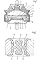
- the motor bearing shown in Figure 1 comprises the support 1 and the support bearing 4, which are connected by the hollow-conical support spring 2 and supported on each other.
- the support is cup-shaped and rests on the outside against the underside of the partition 3, against which it is sealed by the bead on the edge of the buffer wall 6 made of resilient material.
- the buffer wall 6 and the partition wall 3 jointly delimit the compensation space 7.
- a liquid preferably with water containing an antifreeze.
- the partition 3 contains a gas-filled cavity 9.
- the pressure of the gas contained in the cavity is set to a certain value and can be both above and below the atmospheric pressure. It brings about a mutual elastic support of the parts of the boundary walls of the chamber 9 which are elastically displaceable in the direction of the working space 5 and in the direction of the compensation space 7. These are formed on the side facing the compensation space 7 by the disk 12 including the associated ring membrane 14 on which Side facing the working space by two discs 11, 13 which follow one another in the radial direction and which are elastically fixed to one another by interposed ring membranes.
- FIG. 2 shows the ring membranes used in FIG. 1 in a longitudinal section. These have, on the opposite sides, two axial ring projections 17 which are assigned to one another in mirror image and to which stop surfaces 18 of further ring projections which extend essentially in the radial direction are assigned at a distance. These are assigned to the ring projections in mirror image and serve to limit the axial mobility of the disks defined by the ring membranes to a certain extent. The relevant value is due to the mutual contact of the ring projections 16, 17 with the respective opposite
Landscapes
- Engineering & Computer Science (AREA)
- General Engineering & Computer Science (AREA)
- Mechanical Engineering (AREA)
- Combined Devices Of Dampers And Springs (AREA)
- Arrangement Or Mounting Of Propulsion Units For Vehicles (AREA)
Applications Claiming Priority (2)
| Application Number | Priority Date | Filing Date | Title |
|---|---|---|---|
| DE3501111A DE3501111C2 (de) | 1985-01-15 | 1985-01-15 | Motorlager |
| DE3501111 | 1985-01-15 |
Publications (2)
| Publication Number | Publication Date |
|---|---|
| EP0189509A1 true EP0189509A1 (fr) | 1986-08-06 |
| EP0189509B1 EP0189509B1 (fr) | 1988-06-22 |
Family
ID=6259871
Family Applications (1)
| Application Number | Title | Priority Date | Filing Date |
|---|---|---|---|
| EP85105103A Expired EP0189509B1 (fr) | 1985-01-15 | 1985-04-26 | Support de moteur |
Country Status (5)
| Country | Link |
|---|---|
| US (1) | US4664360A (fr) |
| EP (1) | EP0189509B1 (fr) |
| JP (1) | JPS61167733A (fr) |
| DE (2) | DE3501111C2 (fr) |
| ES (1) | ES287946Y (fr) |
Families Citing this family (6)
| Publication number | Priority date | Publication date | Assignee | Title |
|---|---|---|---|---|
| US4756513A (en) * | 1986-11-10 | 1988-07-12 | General Motors Corporation | Variable hydraulic-elastomeric mount assembly |
| DE3815371A1 (de) * | 1988-05-05 | 1989-11-16 | Ingenieurtechnik Mair Gmbh | Tilgerelement |
| KR0168380B1 (ko) * | 1993-11-10 | 1999-01-15 | 전성원 | 유압식 엔진 장착장치 |
| US6485005B1 (en) | 2000-11-03 | 2002-11-26 | Delphi Technologies, Inc. | Hydraulic mount with gas spring supported decoupler |
| JP4603014B2 (ja) * | 2007-06-21 | 2010-12-22 | 東洋ゴム工業株式会社 | 液封入式防振装置 |
| JP4603015B2 (ja) * | 2007-06-21 | 2010-12-22 | 東洋ゴム工業株式会社 | 液封入式防振装置 |
Citations (6)
| Publication number | Priority date | Publication date | Assignee | Title |
|---|---|---|---|---|
| DE2947018A1 (de) * | 1979-11-22 | 1981-05-27 | Audi Nsu Auto Union Ag, 7107 Neckarsulm | Elastisches lager, insbesondere zur lagerung einer brennkraftmaschine in einem kraftfahrzeug |
| EP0058408A2 (fr) * | 1981-02-17 | 1982-08-25 | Nissan Motor Co., Ltd. | Support rempli de fluide pour moteur |
| EP0115417A2 (fr) * | 1983-01-25 | 1984-08-08 | Avon Industrial Polymers Limited | Dispositif de montage à amortissement hydraulique |
| EP0129780A2 (fr) * | 1983-06-28 | 1985-01-02 | Metzeler Kautschuk Gmbh | Membrane séparatrice pour support de moteur à deux chambres |
| EP0133588A2 (fr) * | 1983-08-15 | 1985-02-27 | Bridgestone Corporation | Dispositif et système isolateurs de vibrations |
| EP0164081A2 (fr) * | 1984-06-07 | 1985-12-11 | METZELER Gesellschaft mit beschränkter Haftung | Support de moteur à deux chambres et à amortissement hydraulique |
Family Cites Families (10)
| Publication number | Priority date | Publication date | Assignee | Title |
|---|---|---|---|---|
| US3128978A (en) * | 1964-04-14 | Vibration cancelling isolation mounts - | ||
| FR2255508B1 (fr) * | 1973-12-21 | 1976-10-08 | Vibrachoc Sa | |
| DE2950109A1 (de) * | 1979-12-13 | 1981-07-02 | Continental Gummi-Werke Ag, 3000 Hannover | Elastisches lager |
| JPS6015806B2 (ja) * | 1980-04-14 | 1985-04-22 | 日産自動車株式会社 | ダンパ付エンジンマウント装置 |
| DE3048888C2 (de) * | 1980-12-23 | 1982-11-04 | Audi Nsu Auto Union Ag, 7107 Neckarsulm | Vorrichtung zur elastischen Lagerung von Maschinen oder Maschinenteilen, beispielsweise einer Brennkraftmaschine in einem Kraftfahrzeug |
| DE3125040C2 (de) * | 1981-06-26 | 1985-09-12 | Mair, Christian, 8077 Agelsberg | Elastisches Lager insbesondere zur Lagerung von Maschinen oder Maschinenteilen |
| DE3207889C2 (de) * | 1982-03-05 | 1986-06-19 | Continental Gummi-Werke Ag, 3000 Hannover | Elastisches Lager mit hydraulischer Dämpfung |
| JPS6088133U (ja) * | 1983-11-25 | 1985-06-17 | トヨタ自動車株式会社 | 防振ゴム装置 |
| JPS60167241U (ja) * | 1984-04-13 | 1985-11-06 | 日産自動車株式会社 | 流体入りパワ−ユニツトマウント装置 |
| DE3419437A1 (de) * | 1984-05-24 | 1985-11-28 | Metzeler Kautschuk GmbH, 8000 München | Zweikammer-motorlager mit hydraulischer daempfung |
-
1985
- 1985-01-15 DE DE3501111A patent/DE3501111C2/de not_active Expired
- 1985-04-26 EP EP85105103A patent/EP0189509B1/fr not_active Expired
- 1985-04-26 DE DE8585105103T patent/DE3563471D1/de not_active Expired
- 1985-07-08 ES ES1985287946U patent/ES287946Y/es not_active Expired
- 1985-10-17 US US06/788,339 patent/US4664360A/en not_active Expired - Fee Related
-
1986
- 1986-01-08 JP JP61001948A patent/JPS61167733A/ja active Granted
Patent Citations (6)
| Publication number | Priority date | Publication date | Assignee | Title |
|---|---|---|---|---|
| DE2947018A1 (de) * | 1979-11-22 | 1981-05-27 | Audi Nsu Auto Union Ag, 7107 Neckarsulm | Elastisches lager, insbesondere zur lagerung einer brennkraftmaschine in einem kraftfahrzeug |
| EP0058408A2 (fr) * | 1981-02-17 | 1982-08-25 | Nissan Motor Co., Ltd. | Support rempli de fluide pour moteur |
| EP0115417A2 (fr) * | 1983-01-25 | 1984-08-08 | Avon Industrial Polymers Limited | Dispositif de montage à amortissement hydraulique |
| EP0129780A2 (fr) * | 1983-06-28 | 1985-01-02 | Metzeler Kautschuk Gmbh | Membrane séparatrice pour support de moteur à deux chambres |
| EP0133588A2 (fr) * | 1983-08-15 | 1985-02-27 | Bridgestone Corporation | Dispositif et système isolateurs de vibrations |
| EP0164081A2 (fr) * | 1984-06-07 | 1985-12-11 | METZELER Gesellschaft mit beschränkter Haftung | Support de moteur à deux chambres et à amortissement hydraulique |
Also Published As
| Publication number | Publication date |
|---|---|
| DE3563471D1 (en) | 1988-07-28 |
| DE3501111C2 (de) | 1986-12-04 |
| US4664360A (en) | 1987-05-12 |
| ES287946U (es) | 1985-12-16 |
| JPS61167733A (ja) | 1986-07-29 |
| EP0189509B1 (fr) | 1988-06-22 |
| DE3501111A1 (de) | 1986-07-17 |
| JPH0258495B2 (fr) | 1990-12-07 |
| ES287946Y (es) | 1986-07-16 |
Similar Documents
| Publication | Publication Date | Title |
|---|---|---|
| DE69006230T2 (de) | Oberes Lager für Stossdämpfer in Aufhängungssystemen. | |
| DE2727244C2 (de) | Gummifeder mit Flüssigkeitsfüllung | |
| DE2905090C2 (de) | Gummilager mit hydraulischer Dämpfung | |
| EP0209883B1 (fr) | Support de moteur à amortissement hydraulique et à deux chambres | |
| DE3506047A1 (de) | Vibrationsisolator | |
| DE4120970A1 (de) | Elastische lagerung mit einer fluidfuellung | |
| DE3139915A1 (de) | Luftgedaempftes gummilager | |
| DE69008264T2 (de) | Verbesserungen an hydraulischen Schwingungsdämpfern. | |
| DE69009632T2 (de) | Flüssigkeitsgefülltes Oberlager für Stossdämpfer mit einem Paar abgeflächter, konischer, elastischer Teile. | |
| DE68925650T2 (de) | Flüssigkeitsgefüllte Buchsenfeder mit einem beweglichen Glied in der Flüssigkeitskammer | |
| DE69010732T2 (de) | Oberes Lager für einen Stossdämpfer in einem Aufhängungssystem. | |
| DE3827124C2 (de) | Strömungsmittelgefülltes elastisches Lager | |
| DE10143778A1 (de) | Vibrationsdämpfungsvorrichtung für ein Fahrzeug | |
| DE69013257T2 (de) | Obere Halterung für einen Radaufhängungsstossdämpfer mit elastisch gelagertem Resonanzglied. | |
| EP0189510B1 (fr) | Support de moteur | |
| DE112009001615T5 (de) | Fluidgefüllter Schwingungsdämpfer | |
| DE3617813C2 (fr) | ||
| DE3512840C2 (fr) | ||
| DE3213588C2 (de) | Motorlager | |
| EP0415001A1 (fr) | Support hydraulique | |
| EP0189509B1 (fr) | Support de moteur | |
| DE3913819C2 (fr) | ||
| DE2929084C2 (de) | Schwingungsdämpfendes Lager | |
| DE69003293T2 (de) | Elastische, hydraulisch gedämpfte Buchse mit radialer Elastizität und Entkoppelung der Steifigkeiten. | |
| DE3908718A1 (de) | Elastische triebwerkaufhaengung mit einer fluidfuellung |
Legal Events
| Date | Code | Title | Description |
|---|---|---|---|
| PUAI | Public reference made under article 153(3) epc to a published international application that has entered the european phase |
Free format text: ORIGINAL CODE: 0009012 |
|
| AK | Designated contracting states |
Kind code of ref document: A1 Designated state(s): DE FR GB IT |
|
| 17P | Request for examination filed |
Effective date: 19860619 |
|
| 17Q | First examination report despatched |
Effective date: 19871007 |
|
| ITF | It: translation for a ep patent filed | ||
| GRAA | (expected) grant |
Free format text: ORIGINAL CODE: 0009210 |
|
| AK | Designated contracting states |
Kind code of ref document: B1 Designated state(s): DE FR GB IT |
|
| GBT | Gb: translation of ep patent filed (gb section 77(6)(a)/1977) | ||
| REF | Corresponds to: |
Ref document number: 3563471 Country of ref document: DE Date of ref document: 19880728 |
|
| ET | Fr: translation filed | ||
| PLBE | No opposition filed within time limit |
Free format text: ORIGINAL CODE: 0009261 |
|
| STAA | Information on the status of an ep patent application or granted ep patent |
Free format text: STATUS: NO OPPOSITION FILED WITHIN TIME LIMIT |
|
| 26N | No opposition filed | ||
| ITTA | It: last paid annual fee | ||
| PGFP | Annual fee paid to national office [announced via postgrant information from national office to epo] |
Ref country code: DE Payment date: 19950323 Year of fee payment: 11 |
|
| PGFP | Annual fee paid to national office [announced via postgrant information from national office to epo] |
Ref country code: GB Payment date: 19950330 Year of fee payment: 11 |
|
| PGFP | Annual fee paid to national office [announced via postgrant information from national office to epo] |
Ref country code: FR Payment date: 19950331 Year of fee payment: 11 |
|
| PG25 | Lapsed in a contracting state [announced via postgrant information from national office to epo] |
Ref country code: DE Effective date: 19960126 |
|
| PG25 | Lapsed in a contracting state [announced via postgrant information from national office to epo] |
Ref country code: GB Effective date: 19960426 |
|
| GBPC | Gb: european patent ceased through non-payment of renewal fee |
Effective date: 19960426 |
|
| PG25 | Lapsed in a contracting state [announced via postgrant information from national office to epo] |
Ref country code: FR Effective date: 19961227 |
|
| REG | Reference to a national code |
Ref country code: FR Ref legal event code: ST |