EP0189530B1 - Element zum Verankern von mit diesem vereinigbaren Wandteilen in der hinterschnittenen, einen Öffnungsschlitz aufweisenden Längsnut eines Aufnahmeteils - Google Patents
Element zum Verankern von mit diesem vereinigbaren Wandteilen in der hinterschnittenen, einen Öffnungsschlitz aufweisenden Längsnut eines Aufnahmeteils Download PDFInfo
- Publication number
- EP0189530B1 EP0189530B1 EP85113769A EP85113769A EP0189530B1 EP 0189530 B1 EP0189530 B1 EP 0189530B1 EP 85113769 A EP85113769 A EP 85113769A EP 85113769 A EP85113769 A EP 85113769A EP 0189530 B1 EP0189530 B1 EP 0189530B1
- Authority
- EP
- European Patent Office
- Prior art keywords
- enlargement
- head part
- slot
- tail part
- tail
- Prior art date
- Legal status (The legal status is an assumption and is not a legal conclusion. Google has not performed a legal analysis and makes no representation as to the accuracy of the status listed.)
- Expired - Lifetime
Links
- 238000004873 anchoring Methods 0.000 title claims abstract description 9
- 239000000463 material Substances 0.000 claims abstract description 10
- 238000003780 insertion Methods 0.000 claims abstract description 7
- 230000037431 insertion Effects 0.000 claims abstract description 7
- 239000011343 solid material Substances 0.000 claims abstract description 5
- 229920002994 synthetic fiber Polymers 0.000 claims 1
- 210000000078 claw Anatomy 0.000 description 5
- 239000002184 metal Substances 0.000 description 4
- 238000013459 approach Methods 0.000 description 1
- 230000001419 dependent effect Effects 0.000 description 1
- 238000011161 development Methods 0.000 description 1
- 230000018109 developmental process Effects 0.000 description 1
- 230000000694 effects Effects 0.000 description 1
- 230000002349 favourable effect Effects 0.000 description 1
- 239000004753 textile Substances 0.000 description 1
Images

Classifications
-
- F—MECHANICAL ENGINEERING; LIGHTING; HEATING; WEAPONS; BLASTING
- F16—ENGINEERING ELEMENTS AND UNITS; GENERAL MEASURES FOR PRODUCING AND MAINTAINING EFFECTIVE FUNCTIONING OF MACHINES OR INSTALLATIONS; THERMAL INSULATION IN GENERAL
- F16B—DEVICES FOR FASTENING OR SECURING CONSTRUCTIONAL ELEMENTS OR MACHINE PARTS TOGETHER, e.g. NAILS, BOLTS, CIRCLIPS, CLAMPS, CLIPS OR WEDGES; JOINTS OR JOINTING
- F16B5/00—Joining sheets or plates, e.g. panels, to one another or to strips or bars parallel to them
- F16B5/06—Joining sheets or plates, e.g. panels, to one another or to strips or bars parallel to them by means of clamps or clips
- F16B5/0692—Joining sheets or plates, e.g. panels, to one another or to strips or bars parallel to them by means of clamps or clips joining flexible sheets to other sheets or plates or to strips or bars
-
- E—FIXED CONSTRUCTIONS
- E04—BUILDING
- E04F—FINISHING WORK ON BUILDINGS, e.g. STAIRS, FLOORS
- E04F10/00—Sunshades, e.g. Florentine blinds or jalousies; Outside screens; Awnings or baldachins
- E04F10/02—Sunshades, e.g. Florentine blinds or jalousies; Outside screens; Awnings or baldachins of flexible canopy materials, e.g. canvas ; Baldachins
-
- E—FIXED CONSTRUCTIONS
- E04—BUILDING
- E04H—BUILDINGS OR LIKE STRUCTURES FOR PARTICULAR PURPOSES; SWIMMING OR SPLASH BATHS OR POOLS; MASTS; FENCING; TENTS OR CANOPIES, IN GENERAL
- E04H15/00—Tents or canopies, in general
- E04H15/32—Parts, components, construction details, accessories, interior equipment, specially adapted for tents, e.g. guy-line equipment, skirts, thresholds
- E04H15/64—Tent or canopy cover fastenings
- E04H15/642—Tent or canopy cover fastenings with covers held by elongated fixing members locking in longitudinal recesses of a frame
- E04H15/644—Tent or canopy cover fastenings with covers held by elongated fixing members locking in longitudinal recesses of a frame the fixing members being a beading
-
- E—FIXED CONSTRUCTIONS
- E04—BUILDING
- E04H—BUILDINGS OR LIKE STRUCTURES FOR PARTICULAR PURPOSES; SWIMMING OR SPLASH BATHS OR POOLS; MASTS; FENCING; TENTS OR CANOPIES, IN GENERAL
- E04H15/00—Tents or canopies, in general
- E04H15/32—Parts, components, construction details, accessories, interior equipment, specially adapted for tents, e.g. guy-line equipment, skirts, thresholds
- E04H15/64—Tent or canopy cover fastenings
- E04H15/642—Tent or canopy cover fastenings with covers held by elongated fixing members locking in longitudinal recesses of a frame
- E04H15/646—Tent or canopy cover fastenings with covers held by elongated fixing members locking in longitudinal recesses of a frame the fixing members being locked by an additional locking member
Definitions
- the invention relates to an element for anchoring wall parts made of deformable flat material or solid material which can be combined therewith in an undercut longitudinal groove of a receiving part having an opening slot, as defined in the preamble of claim 1.
- U-shaped clamps for clamping onto sheet metal edges are known, which are used in particular for fastening edge strips to motor vehicles.
- the U-shaped brackets are provided with three claws projecting beyond the bracket walls, of which two are provided on the side edges of one bracket leg and the third approximately in the middle of the other bracket leg.
- the clamps are first attached to the relevant sheet metal edge, then a cover strip covering the sheet metal edge and provided with obliquely inward-pointing support edges is pushed over the clips.
- the outwardly projecting sections of the claws serve to cover or. Anchoring the skirting board on the brackets. This is done in that the support edges of the cover strip finally get behind the outwardly directed claw sections of the U-shaped brackets.
- Such one-piece clamps are not suitable for anchoring wall parts combined with them in the undercut longitudinal groove of a rigid receiving part, the opening slot of which is dimensioned wider than the thickness of the clamps. Rather, the function of such clamps is limited to pushing on them, elastically flexible covering or To hold the edge strips, whereby the unit clip cover strip is fixed on the sheet metal edge by increased friction caused by claws.
- the invention has for its object to provide an element for securely anchoring a combined web of deformable flat material or solid material in the undercut longitudinal groove of a receiving part, the opening slot is wider than the original thickness of the element, so that with the relevant web combined element not from the side, that is, in the longitudinal direction, must be inserted into the longitudinal groove in the receiving part, but can be inserted into this groove from the front.
- FIG. 1 shows a side view of the element with the head and rear parts combined in the initial state and a longitudinal extension indicated in perspective
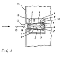
- FIGS. 2 and 3 show an element according to FIG. 1 in its insertion end and locking position in the longitudinal groove of a receiving part, the element in the case of FIG. 3 being inserted into the groove in reverse, ie with the rear part ahead.
- the element consists of a head part 1 designed as a hollow body and of a rear part 2 detachably combined therewith.
- the head part is approximately hollow box-shaped and has an insertion slot 4 on its rear wall 3 Provide rear section. The latter points to his.
- Front a wedge-like extension 5 and in its rear area a wedge-like extension 6, the wedge strength or wedge height of the extension 6 being larger than that of the extension 5.
- Both extensions 5 and 6 have undercuts 5 'and 6' and are by means of a Web 7 connected to each other.
- At least one rib-shaped extension 10, 11 is provided on the inside of the two side walls 8, 9 of the head part, each of which projects inwards and engages behind the front-side extension 5 of the rear part 2 in the starting position of the element according to FIG. 1.
- the two approaches 10 and 11 serve simultaneously as a guide for the web 7 of the rear part.
- FIG. 2 shows, when the element is pushed in through the opening slot 12 into the interior of the longitudinal groove 13 in the receiving part 14, the front of the head part comes into contact with the inner wall 15 of the longitudinal groove, as a result of which the rear part is displaced relative to the head part or the insertion force is maintained. moved on.
- the wedge effect exerted by the wedge-like extension 6 on the end faces of the two wall parts 3 'and 3 "delimiting the insertion slot 4 these wall parts are pressed apart.
- the two wall parts 3' and 3" of the head part finally undercut the undercuts 6 The wedge-like extension 6.
- the rear part is fixed in position within the head part.
- the wall parts 3 'and 3 "of the head part come into contact with the inner sides 16 and 16' of the longitudinal groove 13, as a result of which the element is secured against being pulled out of the opening slot 12 of the longitudinal groove 13 of the receiving part 14.
- the head part can also have another suitable hollow or cross-sectional shape, and the rear part can also be modified accordingly. Together is essential men impact of the head and tail in the sense of the invention.
- a so-called hard or soft plastic is suitable as the material, for example injectable hard or soft PVC.
- the wall part 17 consisting of deformable flat material or of solid material can be attached to the rear 6 ′′ of the wedge-like extension 6 of the rear part 1.
- the wedge-like extension 6 can optionally also be designed without a cavity and have a full cross-section.
- wall parts 17 can be provided with a hemstitch into which the element is inserted.
- a hemstitch is indicated in dashed lines in FIG. 2 and designated 18.
- the element serves, for example, as a piping for anchoring awnings in the undercut groove of a hollow shaft.
- the element is inserted in reverse into the longitudinal groove 13 of the receiving part 14, that is to say with the rear part 2 ahead (see arrow direction).
- This type of insertion is particularly suitable when material webs 17 provided with a hemstitch 18, for example in the form of an awning or the like, are to be anchored in the longitudinal groove.
- the course of the hemstitch in the area of the opening slot of the longitudinal groove is more favorable in this case because of the front side of the head part located here.
- the element is to be inserted with its head part 1 or with its rear part 2 ahead through the opening slot 12 into the longitudinal groove of the receiving part depends on the given conditions with regard to the nature of the wall parts to be anchored and the design and depth of the longitudinal groove of the receiving part .
Landscapes
- Engineering & Computer Science (AREA)
- Architecture (AREA)
- Civil Engineering (AREA)
- Structural Engineering (AREA)
- General Engineering & Computer Science (AREA)
- Mechanical Engineering (AREA)
- Dowels (AREA)
- Joining Of Building Structures In Genera (AREA)
Description
- Die Erfindung bezieht sich auf ein Element zum Verankern von mit diesem vereinigbaren Wandteilen aus verformbarem Flachmaterial oder aus festem Material in einer hinterschnittenen, einen Offnungsschlitz aufweisenden Längsnut eines Aufnahmeteil, wie es im Oberbegriff des Anspruchs 1 definiert ist.
- Durch die FR-A-1 333 639 sind einteilige, u-förmig ausgebildete Klammern zum Anklemmen auf Blechkanten bekannt, die insbesondere zur Befestigung von Randleisten an Kraftfahrzeugen dienen. Die u-förmigen Klammern sind dabei mit drei über die Klammerwandungen überstehenden, schräg nach innen gerichteten Krallen versehen, von denen zwei an den Seitenkanten des einen Klammerschenkels und die dritte etwa in der Mitte des anderen Klammerschenkels vorgesehen sind. Mittels dieser Krallen erfolgt zunächst die Befestigung der Klammern auf der betreffenden Blechkante, danach wird über die Klammern eine die Blechkante überdeckende, mit schräg nach innen weisenden Stützkanten versehene Abdeckleiste geschoben. Die nach außen ragenden Abschnitte der Krallen dienen dabei dazu, die Abdeck-bzw. Randleiste auf den Klammern zu verankern. Dies geschieht dadurch, daß die Stützkanten der Abdeckleiste schließlich hinter die nach außen gerichteten Krallenabschnitte der u-förmigen Klammern gelangen.
- Derartige, einteilig ausgestaltete Klammern eignen sich nicht zum Verankern von mit ihnen vereinigten Wandteilen in der hinterschittenen Längsnut eines starren Aufnahmeteils, deren Öffnungsschlitz breiter bemessen ist als die Stärke der Klammern. Die Funktion solcher Klammern erschöpft sich vielmehr darin, auf sie aufschiebbare, elastisch nachgiebige Abdeckbzw. Randleisten festzuhalten, wobei die Einheit Klammern-Abdeckleiste durch mittels Krallen bewirkter erhöhter Reibung auf der Blechkante fixiert ist.
- Der Erfindung liegt die Aufgabe zugrunde, ein Element zum sicheren Verankern einer mit diesem vereinigten Warenbahn aus verformbarem Flachmaterial oder aus festem Material in der hinterschnittenen Längsnut eines Aufnahmeteils zu schaffen, deren Öffnungsschlitz breiter bemessen ist als die ursprüngliche Stärke des Elements, so daß das mit der betreffende Warenbahn vereinigte Element nicht von der Seite her, also in Längsrichtung, in die Längsnut im Aufnahmeteil eingeschoben werden muß, sondern von der Frontseite her in diese Nut eingeführt werden kann.
- Diese Aufgabe ist durch ein Element gemäß dem Oberbegriff des Patentanspruchs 1 mit den erfindungsgemäßen Merkmalen im kennzeichnenden Teil dieses Anspruchs gelöst. Mit dieser Lösung wird eine einfache, zeitsparende und nur wenig Kraftaufwand erfordernde Verankerung des Elements mit der von diesem gehaltenen Warenbahn in der hinterschnittenen Längsnut des Aufnahmeteils ermöglicht.
- Weiterbildungen und zweckmäßige Ausgestaltungen der Erfindung sind in den abhängigen Ansprüchen charakterisiert.
- Ein Ausführungsbeispiel der Erfindung wird im nachstshenden anhand der Zeichnung erläutert.
- Es zeigen: Figur 1 eine Seitenansicht des Elements bei vereinigtem Kopf-und Heckteil im Ausgangs zustand und perspektivisch angedeuteter Längserstreckung,
- Figuren 2 und 3 ein Element gemäß Figur 1 in seiner Einführungsend-und Verriegelungslage in der Längsnut eines Aufnahmeteils, wobei das Element im Falle der Figur 3 umgekehrt, also mit dem Heckteil voraus, in die Nut eingeschoben ist.
- Wie die Figuren 1 bis 3 erkennen lassen, besteht das Element aus einem als Hohlkörper ausgebildeten Kopfteil 1 und aus einem mit diesem lösbar vereinigten Heckteil 2. Das Kopfteil ist beim Ausführungsbeispiel etwa hohlkastenförmig ausgestaltet und an seiner heckseitig gelegenen Wandung 3 mit einem Einführschlitz 4 für das Heckteil versehen. Letzteres weist an seiner.
- Frontseite eine keilartige Erweiterung 5 und in seinem rückwärtigen Bereich eine keilartige Erweiterung 6 auf, wobei die Keilstärke bzw. Keilhöhe der Erweiterung 6 größer bemessen ist als diejenige der Erweiterung 5. Beide Erweiterungen 5 und 6 besitzen Hinterschneidungen 5' und 6' und sind mittels eines Stegs 7 miteinander verbunden. An der Innenseite der beiden Seitenwandungen 8, 9 des Kopfteils ist jeweils wenigstens ein rippenförmiger Ansatz 10, 11 vorgesehen, von denen jeder nach innen ragt und in der Ausgangslage des Elements gemäß Figur 1 die frontseitige Erweiterung 5 des Heckteils 2 hintergreift. Die beiden Ansätze 10 und 11 dienen dabei gleichzeitig als Führung für den Steg 7 des Heckteils.
- Wie Figur 2 zeigt, kommt beim Einschieben des Elements durch den Öffnungsschlitz 12 hindurch in das Innere der Längsnut 13 im Aufnahmeteil 14 die Frontseite des Kopfteils zur Anlage an die Innenwandung 15 der Längsnut, wodurch sich bei aufrechterhaltener Einschubkraft das Heckteil relativ zum Kopfteil verschiebt bzw. weiterbewegt. Infolge der dabei durch die keilartige Erweiterung 6 auf die Stirnseiten der beiden den Einführschlitz 4 begrenzenden Wandungsteile 3' und 3" ausgeübten Keilwirkung werden diese Wandungsteile auseinandergedrückt. In der Endlage des Heckteils hinterfassen die beiden Wandungsteile 3' und 3" des Kopfteils schließlich die Hinterschneidungen 6' der keilartigen Erweiterung 6. Damit ist das Heckteil innerhalb des Kopfteils in seiner Lage fixiert. Zugleich kommen die Wandungsteile 3' und 3" des Kopfteils zur Anlage an die Innenseiten 16 und 16' der Längsnut 13, wodurch das Element gegen Herausziehen aus dem Öffnungsschlitz 12 der Längsnut 13 des Aufnahmeteils 14 gesichert ist.
- Anstelle der beim Ausführungsbeispiel gewählten Hohlkastenform mit frontseitiger Abrundung kann das Kopfteil auch eine andere geeignete Hohl- bzw. Querschnittsform aufweisen, desgleichen kann das Heckteil entsprechend modifiziert werden. Wesentlich ist das Zusammenwirken des Kopf- und Heckteils im Sinne der Erfindung.
- Als Werkstoff eignet sich je nach Anwendungsfall ein sogenannter harter oder weicher Kunststoff, beispielsweise spritzfähiges Hartoder Weich-PVC.
- Das aus verformbarem Flachmaterial oder aus festem Material bestehende Wandteil 17 kann an der Rückseite 6" der keilartigen Erweiterung 6 des Heckteils 1 befestigt werden. Die keilartige Erweiterung 6 kann gegebenenfalls auch ohne Hohlraum ausgeführt sein und Vollquerschnitt besitzen.
- Im Falle aus verformbarem Flachmaterial, beispielsweise aus textilem Material, bestehenden Wandteilen 17 können diese mit einem Hohlsaum versehen sein, in welchen das Element eingeschoben wird. Ein solcher Hohlsaum ist in Fig. 2 gestrichelt angedeutet und mit 18 bezeichnet. In einem solchen Fall dient das Element beispielsweise als Keder bei der Verankerung von Markisen in der hinterschnittenen Nut einer Hohlwelle.
- Im Falle der Figur 3 ist, anders als bei der Darstellung gemäß Figur 2, das Element umgekehrt in die Längsnut 13 des Aufnahmeteils 14 eingeschoben, das heißt, mit dem Heckteil 2 voraus (siehe Pfeilrichtung). Diese Einführart bietet sich insbesondere dann an, wenn mit einem Hohlsaum 18 versehene Materialbahnen 17, zum Beispiel in Form einer Markise oder dergleichen, in der Längsnut verankert werden sollen. Der Hohlsaumverlauf im Bereich des Öffnungsschlitzes der Längsnut ist in diesem Fall wegen der hier befindlichen Frontseite des Kopfteils günstiger. Ob das Element mit seinem Kopfteil 1 oder mit seinem Heckteil 2 voraus durch den Öffnungsschlitz 12 hindurch in die Längsnut des Aufnahmeteils eingeschoben werden soll, hängt von den jeweils gegebenen Voraussetzungen hinsichtlich der Beschaffenheit der zu verankernden Wandteile und der Ausbildung und Tiefe der Längsnut des Aufnahmeteils ab.
Claims (3)
Priority Applications (1)
| Application Number | Priority Date | Filing Date | Title |
|---|---|---|---|
| AT85113769T ATE56255T1 (de) | 1985-01-28 | 1985-10-29 | Element zum verankern von mit diesem vereinigbaren wandteilen in der hinterschnittenen, einen oeffnungsschlitz aufweisenden laengsnut eines aufnahmeteils. |
Applications Claiming Priority (2)
| Application Number | Priority Date | Filing Date | Title |
|---|---|---|---|
| DE3502728 | 1985-01-28 | ||
| DE19853502728 DE3502728A1 (de) | 1985-01-28 | 1985-01-28 | Element zum verankern von mit diesem vereinigbaren wandteilen in der hinterschnittenen, einen oeffnungsschlitz aufweisenden laengsnut eines aufnahmeteils |
Publications (3)
| Publication Number | Publication Date |
|---|---|
| EP0189530A2 EP0189530A2 (de) | 1986-08-06 |
| EP0189530A3 EP0189530A3 (en) | 1988-04-20 |
| EP0189530B1 true EP0189530B1 (de) | 1990-09-05 |
Family
ID=6260940
Family Applications (1)
| Application Number | Title | Priority Date | Filing Date |
|---|---|---|---|
| EP85113769A Expired - Lifetime EP0189530B1 (de) | 1985-01-28 | 1985-10-29 | Element zum Verankern von mit diesem vereinigbaren Wandteilen in der hinterschnittenen, einen Öffnungsschlitz aufweisenden Längsnut eines Aufnahmeteils |
Country Status (3)
| Country | Link |
|---|---|
| EP (1) | EP0189530B1 (de) |
| AT (1) | ATE56255T1 (de) |
| DE (2) | DE3502728A1 (de) |
Families Citing this family (3)
| Publication number | Priority date | Publication date | Assignee | Title |
|---|---|---|---|---|
| DE4032807C1 (de) * | 1990-10-16 | 1992-05-07 | Hans-Peter 7312 Kirchheim De Rueck | |
| GB2366185A (en) * | 2000-08-22 | 2002-03-06 | Eml Ltd | Channel member for support purposes |
| FR3017596A1 (fr) * | 2014-02-17 | 2015-08-21 | Christian Leviel | Ralingue d'ancrage |
Family Cites Families (2)
| Publication number | Priority date | Publication date | Assignee | Title |
|---|---|---|---|---|
| FR1333639A (fr) * | 1962-09-18 | 1963-07-26 | Raymond A | Attache en u, notamment pour le revêtement de bords de panneaux minces |
| FR2484501A1 (fr) * | 1980-06-13 | 1981-12-18 | Michelet Marceau | Cloisons amovibles a double panneaux et elements pour leur realisation |
-
1985
- 1985-01-28 DE DE19853502728 patent/DE3502728A1/de not_active Withdrawn
- 1985-10-29 DE DE8585113769T patent/DE3579583D1/de not_active Expired - Fee Related
- 1985-10-29 EP EP85113769A patent/EP0189530B1/de not_active Expired - Lifetime
- 1985-10-29 AT AT85113769T patent/ATE56255T1/de not_active IP Right Cessation
Also Published As
| Publication number | Publication date |
|---|---|
| EP0189530A2 (de) | 1986-08-06 |
| DE3502728A1 (de) | 1986-07-31 |
| ATE56255T1 (de) | 1990-09-15 |
| DE3579583D1 (de) | 1990-10-11 |
| EP0189530A3 (en) | 1988-04-20 |
Similar Documents
| Publication | Publication Date | Title |
|---|---|---|
| DE1779745C3 (de) | Vorrichtung zum Verbinden einer ersten Möbelwand mit einer zweiten Möbelwand | |
| DE9404642U1 (de) | Verbindungselement | |
| DE69506395T2 (de) | Formteil mit kanal | |
| DE2607240A1 (de) | Wandverkleidung mit befestigungsklammer | |
| DE9301324U1 (de) | Halter | |
| WO2010102735A1 (de) | Paneele | |
| CH649802A5 (en) | Panel-securing means for facade or roof structures | |
| EP1884702A2 (de) | Schelle zur Fixierung strangförmiger Bauteile | |
| DE69614237T2 (de) | Befestigungssystem für eine Kraftfahrzeuginnenverkleidung | |
| DE102014102465B4 (de) | Schaltschrank | |
| DE29607346U1 (de) | Anschlußprofil zwischen Fensterrahmen und Mauerwerksputz im Bereich einer Fensterlaibung | |
| DE3033651C2 (de) | ||
| CH429111A (de) | Mehrteilige Leiste | |
| DE2803972C2 (de) | Zähler- und Verteilerschrank aus Kunststoff-Extruderprofilen | |
| DE6909680U (de) | Rueckwandhalteprofil fuer moebel | |
| DE3212649A1 (de) | Haltevorrichtung fuer sockelleisten od.dgl. verkleidungsprofile | |
| EP0550882A1 (de) | Befestigungsvorrichtung für eine Gebäudewandverkleidung | |
| DE19726887A1 (de) | Profilleiste | |
| DE69711149T2 (de) | Abdichtungsvorrichtung des Stosses zwischen zwei Profilen eines Tür-, Fenster oder dgl. Rahmens | |
| EP0481260B1 (de) | Leistenförmiges Element zum Verankern von mit diesem vereinigbaren Wandteilen in der hinterschnittenen, einen Öffnungsschlitz aufweisenden Längsnut eines Aufnahmeteils | |
| EP0189530A2 (de) | Element zum Verankern von mit diesem vereinigbaren Wandteilen in der hinterschnittenen, einen Öffnungsschlitz aufweisenden Längsnut eines Aufnahmeteils | |
| DE202017102133U1 (de) | Zarge, insbesondere Türzarge | |
| DE9215844U1 (de) | Beschlagteileverbindung | |
| DE4307657C2 (de) | Wand aus Balken oder dergleichen mit einer Abdichtung | |
| DE20004349U1 (de) | Vorrichtung zum Halten von in Mauerschlitzen verlegten Leitungen |
Legal Events
| Date | Code | Title | Description |
|---|---|---|---|
| PUAI | Public reference made under article 153(3) epc to a published international application that has entered the european phase |
Free format text: ORIGINAL CODE: 0009012 |
|
| 17P | Request for examination filed |
Effective date: 19851029 |
|
| AK | Designated contracting states |
Kind code of ref document: A2 Designated state(s): AT BE CH DE FR GB IT LI NL |
|
| PUAL | Search report despatched |
Free format text: ORIGINAL CODE: 0009013 |
|
| AK | Designated contracting states |
Kind code of ref document: A3 Designated state(s): AT BE CH DE FR GB IT LI NL |
|
| 17Q | First examination report despatched |
Effective date: 19890306 |
|
| GRAA | (expected) grant |
Free format text: ORIGINAL CODE: 0009210 |
|
| AK | Designated contracting states |
Kind code of ref document: B1 Designated state(s): AT BE CH DE FR GB IT LI NL |
|
| REF | Corresponds to: |
Ref document number: 56255 Country of ref document: AT Date of ref document: 19900915 Kind code of ref document: T |
|
| REF | Corresponds to: |
Ref document number: 3579583 Country of ref document: DE Date of ref document: 19901011 |
|
| PGFP | Annual fee paid to national office [announced via postgrant information from national office to epo] |
Ref country code: FR Payment date: 19901017 Year of fee payment: 6 |
|
| PGFP | Annual fee paid to national office [announced via postgrant information from national office to epo] |
Ref country code: GB Payment date: 19901019 Year of fee payment: 6 |
|
| PGFP | Annual fee paid to national office [announced via postgrant information from national office to epo] |
Ref country code: AT Payment date: 19901023 Year of fee payment: 6 |
|
| PGFP | Annual fee paid to national office [announced via postgrant information from national office to epo] |
Ref country code: CH Payment date: 19901030 Year of fee payment: 6 |
|
| PGFP | Annual fee paid to national office [announced via postgrant information from national office to epo] |
Ref country code: NL Payment date: 19901031 Year of fee payment: 6 |
|
| ITF | It: translation for a ep patent filed | ||
| ET | Fr: translation filed | ||
| GBT | Gb: translation of ep patent filed (gb section 77(6)(a)/1977) | ||
| PGFP | Annual fee paid to national office [announced via postgrant information from national office to epo] |
Ref country code: BE Payment date: 19910116 Year of fee payment: 6 |
|
| PGFP | Annual fee paid to national office [announced via postgrant information from national office to epo] |
Ref country code: DE Payment date: 19910429 Year of fee payment: 6 |
|
| PLBE | No opposition filed within time limit |
Free format text: ORIGINAL CODE: 0009261 |
|
| STAA | Information on the status of an ep patent application or granted ep patent |
Free format text: STATUS: NO OPPOSITION FILED WITHIN TIME LIMIT |
|
| 26N | No opposition filed | ||
| PG25 | Lapsed in a contracting state [announced via postgrant information from national office to epo] |
Ref country code: GB Effective date: 19911029 Ref country code: AT Effective date: 19911029 |
|
| ITTA | It: last paid annual fee | ||
| PG25 | Lapsed in a contracting state [announced via postgrant information from national office to epo] |
Ref country code: LI Effective date: 19911031 Ref country code: CH Effective date: 19911031 Ref country code: BE Effective date: 19911031 |
|
| BERE | Be: lapsed |
Owner name: RUCK HANS-PETER Effective date: 19911031 |
|
| PG25 | Lapsed in a contracting state [announced via postgrant information from national office to epo] |
Ref country code: NL Effective date: 19920501 |
|
| NLV4 | Nl: lapsed or anulled due to non-payment of the annual fee | ||
| GBPC | Gb: european patent ceased through non-payment of renewal fee | ||
| PG25 | Lapsed in a contracting state [announced via postgrant information from national office to epo] |
Ref country code: FR Effective date: 19920630 |
|
| REG | Reference to a national code |
Ref country code: CH Ref legal event code: PL |
|
| PG25 | Lapsed in a contracting state [announced via postgrant information from national office to epo] |
Ref country code: DE Effective date: 19920701 |
|
| REG | Reference to a national code |
Ref country code: FR Ref legal event code: ST |