EP0189549B1 - Dispositif d'écoulement pour médias coulants - Google Patents
Dispositif d'écoulement pour médias coulants Download PDFInfo
- Publication number
- EP0189549B1 EP0189549B1 EP85115117A EP85115117A EP0189549B1 EP 0189549 B1 EP0189549 B1 EP 0189549B1 EP 85115117 A EP85115117 A EP 85115117A EP 85115117 A EP85115117 A EP 85115117A EP 0189549 B1 EP0189549 B1 EP 0189549B1
- Authority
- EP
- European Patent Office
- Prior art keywords
- bacteria filter
- filter
- wall surface
- discharge
- ring seal
- Prior art date
- Legal status (The legal status is an assumption and is not a legal conclusion. Google has not performed a legal analysis and makes no representation as to the accuracy of the status listed.)
- Expired - Lifetime
Links
- 241000894006 Bacteria Species 0.000 claims description 18
- 238000003825 pressing Methods 0.000 claims description 4
- 239000002537 cosmetic Substances 0.000 claims description 3
- 238000003466 welding Methods 0.000 claims description 3
- 230000009969 flowable effect Effects 0.000 claims description 2
- -1 polytetrafluoroethylene Polymers 0.000 claims description 2
- 229920001343 polytetrafluoroethylene Polymers 0.000 claims description 2
- 239000004810 polytetrafluoroethylene Substances 0.000 claims description 2
- 238000010276 construction Methods 0.000 claims 2
- 238000009423 ventilation Methods 0.000 description 20
- 238000003860 storage Methods 0.000 description 10
- 239000013543 active substance Substances 0.000 description 9
- 230000006835 compression Effects 0.000 description 7
- 238000007906 compression Methods 0.000 description 7
- 238000002360 preparation method Methods 0.000 description 5
- 239000003381 stabilizer Substances 0.000 description 4
- 244000052616 bacterial pathogen Species 0.000 description 3
- 238000004026 adhesive bonding Methods 0.000 description 2
- 230000002070 germicidal effect Effects 0.000 description 2
- 230000035515 penetration Effects 0.000 description 2
- 238000007789 sealing Methods 0.000 description 2
- 238000010521 absorption reaction Methods 0.000 description 1
- 238000005273 aeration Methods 0.000 description 1
- 230000001580 bacterial effect Effects 0.000 description 1
- 239000011324 bead Substances 0.000 description 1
- 238000009395 breeding Methods 0.000 description 1
- 230000001488 breeding effect Effects 0.000 description 1
- 230000000694 effects Effects 0.000 description 1
- 239000013013 elastic material Substances 0.000 description 1
- 239000000835 fiber Substances 0.000 description 1
- 238000009434 installation Methods 0.000 description 1
- 235000015097 nutrients Nutrition 0.000 description 1
- 230000035699 permeability Effects 0.000 description 1
- 239000011148 porous material Substances 0.000 description 1
- 239000005871 repellent Substances 0.000 description 1
- 230000007704 transition Effects 0.000 description 1
Images
Classifications
-
- A—HUMAN NECESSITIES
- A45—HAND OR TRAVELLING ARTICLES
- A45D—HAIRDRESSING OR SHAVING EQUIPMENT; EQUIPMENT FOR COSMETICS OR COSMETIC TREATMENTS, e.g. FOR MANICURING OR PEDICURING
- A45D34/00—Containers or accessories specially adapted for handling liquid toiletry or cosmetic substances, e.g. perfumes
-
- B—PERFORMING OPERATIONS; TRANSPORTING
- B05—SPRAYING OR ATOMISING IN GENERAL; APPLYING FLUENT MATERIALS TO SURFACES, IN GENERAL
- B05B—SPRAYING APPARATUS; ATOMISING APPARATUS; NOZZLES
- B05B11/00—Single-unit hand-held apparatus in which flow of contents is produced by the muscular force of the operator at the moment of use
- B05B11/0005—Components or details
- B05B11/0037—Containers
- B05B11/0039—Containers associated with means for compensating the pressure difference between the ambient pressure and the pressure inside the container, e.g. pressure relief means
- B05B11/0044—Containers associated with means for compensating the pressure difference between the ambient pressure and the pressure inside the container, e.g. pressure relief means compensating underpressure by ingress of atmospheric air into the container, i.e. with venting means
- B05B11/00444—Containers associated with means for compensating the pressure difference between the ambient pressure and the pressure inside the container, e.g. pressure relief means compensating underpressure by ingress of atmospheric air into the container, i.e. with venting means with provision for filtering or cleaning the air flow drawn into the container
-
- B—PERFORMING OPERATIONS; TRANSPORTING
- B05—SPRAYING OR ATOMISING IN GENERAL; APPLYING FLUENT MATERIALS TO SURFACES, IN GENERAL
- B05B—SPRAYING APPARATUS; ATOMISING APPARATUS; NOZZLES
- B05B11/00—Single-unit hand-held apparatus in which flow of contents is produced by the muscular force of the operator at the moment of use
- B05B11/01—Single-unit hand-held apparatus in which flow of contents is produced by the muscular force of the operator at the moment of use characterised by the means producing the flow
- B05B11/10—Pump arrangements for transferring the contents from the container to a pump chamber by a sucking effect and forcing the contents out through the dispensing nozzle
- B05B11/1001—Piston pumps
- B05B11/1023—Piston pumps having an outlet valve opened by deformation or displacement of the piston relative to its actuating stem
- B05B11/1026—Piston pumps having an outlet valve opened by deformation or displacement of the piston relative to its actuating stem the piston being deformable and its deformation allowing opening of the outlet
-
- B—PERFORMING OPERATIONS; TRANSPORTING
- B67—OPENING, CLOSING OR CLEANING BOTTLES, JARS OR SIMILAR CONTAINERS; LIQUID HANDLING
- B67D—DISPENSING, DELIVERING OR TRANSFERRING LIQUIDS, NOT OTHERWISE PROVIDED FOR
- B67D7/00—Apparatus or devices for transferring liquids from bulk storage containers or reservoirs into vehicles or into portable containers, e.g. for retail sale purposes
- B67D7/02—Apparatus or devices for transferring liquids from bulk storage containers or reservoirs into vehicles or into portable containers, e.g. for retail sale purposes for transferring liquids other than fuel or lubricants
- B67D7/0205—Apparatus or devices for transferring liquids from bulk storage containers or reservoirs into vehicles or into portable containers, e.g. for retail sale purposes for transferring liquids other than fuel or lubricants by manually operable pumping apparatus
Definitions
- the invention relates to a discharge device for flowable media contained in a memory, in particular for pharmaceutical and / or cosmetic preparations, according to the preamble of patent claim 1.
- DE-A-2 746 993 has disclosed a discharge device of this type, the filter of which is arranged as an annular coaxial filter between two jacket walls. If you want to achieve a sufficiently large filter area here, then a correspondingly large outside diameter of the filter and a correspondingly large diameter of the receptacle for the filter required. The neck of the storage device receiving the discharge device must then be correspondingly wide, which is why the known design is not suitable for numerous given storage sizes.
- filter arrangements have become known in which the filter is in any case outside the memory.
- the width of the discharge device in the area of the filter is so large that an introduction of this area through the storage neck and into the storage is excluded. It is also not a germ filter, but a water-repellent filter.
- the invention has for its object to provide a discharge device of the type mentioned so that the penetration of germs is largely avoided, such that the addition of germicidal stabilizing agents can be dispensed with even in preparations that could be a breeding ground for germs or the amount of these stabilizers can be significantly reduced.
- a discharge device of the type mentioned so that the penetration of germs is largely avoided, such that the addition of germicidal stabilizing agents can be dispensed with even in preparations that could be a breeding ground for germs or the amount of these stabilizers can be significantly reduced.
- the germ filter preferably consists of a fiber filter made of polytetrafluoroethylene or the like.
- the compact, space-saving housing of the germ filter is further improved by the fact that the germ filter is placed against the wall surface through which the ventilation duct has a through opening and is preferably parallel with a short distance or at constant distances from this wall surface.
- the ventilation channel in the area of the germ filter is sealed with at least one ring seal, the ring seal preferably being formed in one piece with the germ filter, so that even with a relatively heavily added germ filter it is prevented in any case that also only a part of the ventilation air drawn into the active substance storage can bypass the germ filter.
- the, in particular bead-like ring seal is formed by pressing, gluing, welding or the like. the ring seal expediently adjoins the associated wall surface of the dispenser.
- the germ filter is multiple, in particular many times larger than the rest of the cross-section of the ventilation connection, wherein preferably the germ filter with its ring seal and the associated wall surface penetrated by the ventilation channel delimits a filter inlet chamber into which the substantially smaller passage opening, in particular the Germ filter located centrally opposite, opens out.
- a window-like holding frame which is preferably attached directly to the wall surface, such as being welded, glued or the like, and on which the germ filter is preferably attached to the same, ring seal protruding over its thickness on both sides as against the wall surface, so that a good sealing pressure can be achieved.
- the germ filter lies within the active substance store mentioned, as a result of which it is effectively protected against mechanical loads or damage and only comes into contact with the air which flows into the store through the ventilation connection for volume compensation.
- a particularly simple assembly is obtained if the germ filter is arranged on an active substance discharge pump, such as the housing of a manually operated piston pump.
- the germ filter is expediently arranged at approximately constant intervals on a wall surface which is approximately curved about the central axis of the discharge channel and / or immediately afterwards on a fastening flange of the discharge pump which projects above this wall surface.
- the pump housing is in two parts, for example composed of a cylinder housing guiding the pump piston and a storage end cap closing it at the outer end, the germ filter is expediently only attached to one of these two components, preferably to the cylinder housing.
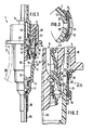
- the discharge pump 1 has an active substance store, which is otherwise not shown in detail, which is essentially axially symmetrical Pump housing 2, which consists essentially of a gradually narrowing towards the inner end of the cylinder housing 3 and an end cap 4, which is attached to the outer, furthest end of the housing 3 by clip-like snap-in so that it covers the jacket of the Cylinder housing 3 in the area of the associated end overlaps both on the inner and on the outer circumference.
- a pump piston 6 is slidably guided with a piston sleeve 7 made of elastic material, which tapers in the manner of a truncated cone to the outer end of the housing 2 and tapers with it inner end is guided in the manner of an annular sealing lip on the track 5.
- a piston sleeve 7 made of elastic material, which tapers in the manner of a truncated cone to the outer end of the housing 2 and tapers with it inner end is guided in the manner of an annular sealing lip on the track 5.
- an elastic compression sleeve 8 which is formed in one piece therewith, the outer end of which is fastened to a piston tappet 9 by annular clamping.
- the piston tappet 9 which protrudes from the cap 4 for manual operation, has a discharge channel 11 for the active substance which extends from the pump chamber 10 receiving the piston 6 to its outer end, the discharge channel 11 through the interior of the piston sleeve 7 and the Compression sleeve 8 leads.
- a discharge valve 12 is provided, the annular movable valve closing part of which is formed by a valve lip projecting annularly over the inner surface of the component which forms the piston sleeve 7 and / or the compression sleeve 8.
- the valve seat 14 for this valve closing part 13 is formed by the piston tappet 9 and is flared at an obtuse angle towards the inner end of the discharge pump 1.
- the valve closing part 13 is pressed against the valve seat 14 by the axial prestressing of the compression sleeve 8.
- the discharge valve 12 can be designed as a pressure relief valve or, as in the exemplary embodiment shown, as a mechanically opening valve which is opened at the end of the pump stroke by running the piston sleeve 7 onto a stop shoulder 15 of the pump housing 2.
- the pump piston 6 is loaded by a prestressed return spring 16 arranged in the cylinder housing 3, which is supported on the one hand at the inner end of the piston rod 9 and on the other hand in the region of an inlet valve 17 designed as a check valve for the pump chamber 10 relative to the pump housing 2.
- the discharge pump 1 is expediently arranged in or in the storage indicated by dash-dotted lines at 20 in such a way that the pump housing 2 engages in the neck 21 of the storage 20 following the end cap 4 and one provided on the cap 4 and above it
- the circumferential projecting annular fastening flange 22 is sealed against the outer end face of the neck 21.
- a discharge channel 23 leads through the discharge pump 1 as a ventilation connection between the interior of the reservoir 20 and the outside atmosphere.
- the ventilation channel 23 is formed between the outside atmosphere and a ventilation valve 24 located inside the pump housing 2 in a filter inlet chamber 25 by an annular gap, which is located radially on the inside is delimited by the outer section of the piston tappet 9 and the compression sleeve 8 adjoining it and radially on the outside by an inner sleeve 26 which that engages in the cylinder housing 3 section of the end cap 4.
- the wall 27 of the housing 3 is penetrated by an axially slot-shaped passage opening 28, which establishes the ventilation connection to the inlet chamber 25 and the interior of the store 20.
- the movable valve closing part 29 of the ventilation valve 24 is formed by a portion of the piston sleeve 7 or the compression sleeve 8 which is enlarged in the shape of a truncated cone on the outer circumference against the pump chamber 10, this portion lying essentially in the same axial area as the valve closing part 13.
- the valve seat 30 for the valve closing part 29 the inner end of the inner sleeve 26 is provided, on the radially inner end edge of which the valve closing part 29 bears under initial tension in the initial position of the pump piston 6 such that the discharge valve 12 is simultaneously under closing pressure. In the starting position, both the discharge duct 11 and the ventilation duct 23 are therefore necessarily sealed.
- the valve closing part 29 lifts off the valve seat 30, so that the ventilation valve 24 and thus the ventilation channel 23 are opened into the interior of the accumulator 20.
- a germ filter 31 is arranged, which is placed directly adjacent to the outer periphery of the cylinder housing 3 on its associated wall surface 32.
- the flat, for example circular disc-shaped germ filter 31 is arranged in the region of the passage opening 28 and symmetrically to the axial plane of the discharge pump 1 passing through it in such a way that that of the input chamber 25 ventilation air flowing into the storage 20 can only and completely enter the storage 20 only through the germ filter 31.
- the germ filter 31 is formed in one piece with a circumferential ring seal 33 which is closed adjacent to its outer circumference and projects in the manner of ring beads on both sides approximately equally far beyond the surfaces of the germ filter 31, such that a protruding ring seal is formed on each surface and the two ring seals in View of the germ filter 31 are substantially congruent with each other.
- the germ filter 31 is pressed under pressure on the one hand against the wall surface 32 and on the other hand the ring seal 33 with its side facing away from this wall surface 32 is in contact with a window-like holding frame 34 which, for example, by pressing, gluing, welding or the like on the cylinder -Housing 3, in particular is exclusively attached to the wall surface 32;
- the holding frame 34 is designed so that it is also attached to the end cap 4 in the region of the inner end face of the fastening flange 22, but in most cases it is expedient to hold the holding frame 34 only on one of the two, that Fasten the pump housing 2 forming components and, if necessary, to engage in the end cap 4 in the area of the mounting flange 22.
- the central opening of the holding frame 34 forms the inlet opening for the ventilation air emerging from the germ filter 31 into the reservoir 20; this inlet opening is only slightly smaller than the filter field within the ring seal 33.
- the holding frame 34 is expediently at least partially angular in cross section, so that one angle leg overlaps the ring seal 33 and the other angle leg is used for attachment to the pump housing 2.
- the holding frame 34 can also be formed, for example, by at least one ring or sleeve which is pushed and / or welded onto the pump housing 2, for example by pressing, in such a way that the holding frame surrounds the housing 2 on the outer circumference or in the central axis 35 of the discharge pump 1.
Landscapes
- Engineering & Computer Science (AREA)
- Mechanical Engineering (AREA)
- Containers And Packaging Bodies Having A Special Means To Remove Contents (AREA)
- Medical Preparation Storing Or Oral Administration Devices (AREA)
- Closures For Containers (AREA)
- Details Of Reciprocating Pumps (AREA)
- Reciprocating Pumps (AREA)
- Infusion, Injection, And Reservoir Apparatuses (AREA)
Claims (10)
- Dispositif distributeur pour substances de grande fluidité renfermées par un réservoir (20), en particulier pour préparations pharmaceutiques et/ou cosmétiques, comprenant un corps de base (2, 4) présentant une partie de fixation jusqu'à laquelle le dispositif distributeur peut être introduit dans le réservoir, et par l'intermédiaire de laquelle il peut être relié audit réservoir (20), et une région attenante à la partie de fixation et conçue pour être introduite dans un orifice du réservoir, avec une enveloppe de carter (27) formant des surfaces de paroi périphérique (32), ainsi qu'avec un canal (11) délivreur de la substance, et une liaison de ventilation qui forme un canal de ventilation (23) pour la compensation de volume de la substance délivrée, et traverse un filtre de stérilisation (31) installé sur l'enveloppe de carter, et dans la région d'un orifice (28) de circulation d'air, caractérisé par le fait que le filtre de stérilisation (31) est de réalisation mince et aplatie, et se trouve sur l'une des surfaces de paroi périphérique (32), pour l'essentiel parallèlement et à faible distance de cette dernière, la surface de paroi (32) étant traversée, par l'orifice de circulation (28), pour l'essentiel radialement et transversalement par rapport au filtre aplati de stérilisation (31).
- Dispositif selon la revendication 1, caractérisé par le fait que le filtre de stérilisation (31) est d'une réalisation de type membrane et consiste, de préférence, en un filtre en fibres de polytétrafluoréthylène ou matière similaire.
- Dispositif selon la revendication 1 ou 2, caractérisé par le fait que le filtre de stérilisation (31) est appliqué contre la surface de paroi (32) et se trouve, notamment, à une distance approximativement constante de cette surface de paroi (32) matérialisant, de préférence, une surface périphérique extérieure de l'enveloppe de carter (27).
- Dispositif selon l'une des revendications précédentes, caractérisé par le fait que le canal de ventilation (23) est rendu étanche, dans la région du filtre de stérilisation (31), par au moins une garniture annulaire d'étanchement (33), cette garniture annulaire d'étanchement (33) étant préférentiellement réalisée d'un seul tenant avec le filtre de stérilisation (31).
- Dispositif selon la revendication 4, caractérisé par le fait que la garniture annulaire d'étanchement (33), notamment du type bourrelet, est formée par compression, collage, soudage ou procédé similaire, et/ou est attenante à la surface de paroi associée (32) du dispositif distributeur.
- Dispositif selon l'une des revendications précédentes, caractérisé par le fait que la dimension du filtre de stérilisation (31) est plusieurs fois supérieure à celle du reste de la section transversale de la liaison de ventilation ; et par le fait que le filtre de stérilisation (31) délimite de préférence, avec sa garniture annulaire d'étanchement (33) et la surface de paroi associée (32) traversée par le canal de ventilation (23), une chambre d'entrée de filtration (25) dans laquelle débouche l'orifice de circulation (28) qui est notablement plus petit et se trouve, notamment, en vis-à-vis du filtre de stérilisation (31).
- Dispositif selon l'une des revendications précédentes, caractérisé par le fait que, sur son côté tourné à l'opposé de la surface de paroi (32), le filtre de stérilisation (31) est entouré par un cadre de retenue (34) du type fenêtre, qui est de préférence directement fixé à la surface de paroi (32), par exemple rapporté par soudage, collé ou assujetti d'une manière similaire ; et par le fait que le filtre de stérilisation (31) est notamment appliqué, contre ce cadre de retenue (34), par la même garniture annulaire d'étanchement (33) par laquelle il est appliqué contre la surface de paroi (32), et qui fait de part et d'autre saillie au-delà de son épaisseur.
- Dispositif selon l'une des revendications précédentes, caractérisé par le fait que le filtre de stérilisation (31) est installé sur une pompe (1) de distribution de substances, comme le carter (2) d'une pompe à piston actionnable à la main.
- Dispositif selon l'une des revendications précédentes, caractérisé par le fait que la surface de paroi (32) est curviligne dans la région du filtre de stérilisation (31), en particulier approximativement autour de l'axe médian (35) d'un canal délivreur (11) ; et/ou par le fait que le filtre de stérilisation (31) est installé dans la continuité directe d'une bride (22) de fixation du dispositif distributeur, qui déborde de la surface de paroi (32).
- Dispositif selon l'une des revendications précédentes, caractérisé par le fait qu'une soupape d'évent (24) est prévue dans le canal de ventilation (23) et/ou une soupape de distribution (12) est prévue dans le canal délivreur (11) ; et par le fait que, de préférence, au moins une soupape est fermée à force dans la position initiale de la pompe de distribution (1).
Applications Claiming Priority (2)
| Application Number | Priority Date | Filing Date | Title |
|---|---|---|---|
| DE3503354 | 1985-02-01 | ||
| DE19853503354 DE3503354A1 (de) | 1985-02-01 | 1985-02-01 | Wirkstoff-spender |
Publications (3)
| Publication Number | Publication Date |
|---|---|
| EP0189549A2 EP0189549A2 (fr) | 1986-08-06 |
| EP0189549A3 EP0189549A3 (en) | 1987-08-19 |
| EP0189549B1 true EP0189549B1 (fr) | 1991-10-16 |
Family
ID=6261359
Family Applications (1)
| Application Number | Title | Priority Date | Filing Date |
|---|---|---|---|
| EP85115117A Expired - Lifetime EP0189549B1 (fr) | 1985-02-01 | 1985-11-28 | Dispositif d'écoulement pour médias coulants |
Country Status (4)
| Country | Link |
|---|---|
| US (1) | US4694976A (fr) |
| EP (1) | EP0189549B1 (fr) |
| JP (1) | JPS61178570A (fr) |
| DE (2) | DE3503354A1 (fr) |
Cited By (1)
| Publication number | Priority date | Publication date | Assignee | Title |
|---|---|---|---|---|
| DE102016109612A1 (de) * | 2016-05-25 | 2017-11-30 | Gerresheimer Regensburg Gmbh | Abgabeeinrichtung zur dosierten Abgabe eine sterilen Fluids |
Families Citing this family (40)
| Publication number | Priority date | Publication date | Assignee | Title |
|---|---|---|---|---|
| DE3641390C1 (de) * | 1986-12-04 | 1988-02-11 | Schwan Stabilo Schwanhaeusser | Auftragsgeraet |
| US5039316A (en) * | 1990-03-01 | 1991-08-13 | Critical-Vac Filtration Corporation | Glove bag adaptor control |
| US5074440A (en) * | 1990-07-16 | 1991-12-24 | Alcon Laboratories, Inc. | Container for dispensing preservative-free preparations |
| FR2669379A1 (fr) * | 1990-11-21 | 1992-05-22 | Promotion Rech Innovation Tec | Pompe doseuse pour produits liquides. |
| US5527161A (en) * | 1992-02-13 | 1996-06-18 | Cybor Corporation | Filtering and dispensing system |
| PH30867A (en) | 1992-07-31 | 1997-12-09 | Leiras Oy | Method and equipment for installing a medicine capsule on a support. |
| ATE163578T1 (de) * | 1992-11-11 | 1998-03-15 | Tee Enterprises Ltd | Zerstäuber |
| US5490765A (en) * | 1993-05-17 | 1996-02-13 | Cybor Corporation | Dual stage pump system with pre-stressed diaphragms and reservoir |
| US5353969A (en) * | 1993-10-13 | 1994-10-11 | Calmar Inc. | Invertible pump sprayer having spiral vent path |
| SI9600118A (en) * | 1995-04-13 | 1996-10-31 | Monturas Sa | Precompression pump sprayer |
| EP0861128B1 (fr) * | 1995-11-17 | 2003-02-19 | Ursatec Verpackung Gmbh | Distributeur de fluides protegeant ces derniers contre une contamination |
| DE19610457A1 (de) * | 1996-03-16 | 1997-09-18 | Pfeiffer Erich Gmbh & Co Kg | Austragvorrichtung für Medien |
| DE19627228A1 (de) * | 1996-07-05 | 1998-01-08 | Pfeiffer Erich Gmbh & Co Kg | Austragvorrichtung für Medien |
| FR2762589B1 (fr) * | 1997-04-28 | 1999-07-16 | Sofab | Flacon de distribution pour liquide, creme ou gel comportant un dispositif filtrant de l'air entrant |
| DE19729117A1 (de) * | 1997-07-08 | 1999-01-21 | Erich Wunsch | Spraymechanismus für Dosier-Sprayflaschen |
| FR2781767B1 (fr) | 1998-07-31 | 2000-10-13 | Valois Sa | Dispositif de distribution de produit fluide |
| FR2781768B1 (fr) | 1998-08-03 | 2000-10-13 | Valois Sa | Dispositif de distribution de produit fluide adapte a eviter toute contamination du produit contenu dans le recipient |
| DE19840721A1 (de) * | 1998-09-07 | 2000-03-09 | Pfeiffer Erich Gmbh & Co Kg | Spender für Medien |
| DE19840723A1 (de) | 1998-09-07 | 2000-03-09 | Pfeiffer Erich Gmbh & Co Kg | Spender für Medien |
| US6170713B1 (en) * | 1998-10-28 | 2001-01-09 | Emson, Inc. | Double spring precompression pump with priming feature |
| GB2344857B (en) * | 1998-12-15 | 2001-03-14 | Bespak Plc | Improvements in or relating to dispensing apparatus |
| FR2794727B1 (fr) * | 1999-06-10 | 2001-08-24 | Valois Sa | Dispositif de distribution de produit fluide ameliore |
| FR2798368B1 (fr) * | 1999-09-09 | 2001-11-23 | Valois Sa | Pompe de distribution de produit fluide amelioree, et dispositif de distribution de produit fluide comportant une telle pompe |
| DE10015968A1 (de) * | 2000-03-30 | 2001-10-04 | Pfeiffer Erich Gmbh & Co Kg | Spender für Medien |
| DE20018518U1 (de) * | 2000-10-28 | 2001-02-01 | Boehringer Ingelheim Pharma KG, 55218 Ingelheim | Zerstäuber für Nasenspray |
| DE102005009295A1 (de) * | 2004-07-13 | 2006-02-16 | Ing. Erich Pfeiffer Gmbh | Dosiervorrichtung für Medien |
| DE102004050679A1 (de) * | 2004-10-13 | 2006-04-20 | Ing. Erich Pfeiffer Gmbh | Dosiervorrichtung |
| DE102004050977A1 (de) * | 2004-10-14 | 2006-04-20 | Ing. Erich Pfeiffer Gmbh | Dosiervorrichtung für wenigstens ein Medium |
| DE602005008429D1 (de) * | 2005-08-08 | 2008-09-04 | Guala Dispensing Spa | Lüftungseinsatz für einen Flüssigkeitsspender sowie Verfahren zum Aufbringen einer Membran darauf |
| JP6172741B2 (ja) * | 2013-05-14 | 2017-08-02 | 株式会社三谷バルブ | 内容物放出用ポンプ機構およびこの内容物放出用ポンプ機構を備えたポンプ式製品 |
| WO2015038692A1 (fr) * | 2013-09-13 | 2015-03-19 | Gojo Industries, Inc. | Distributeurs pour récipients non repliables et pompes d'aération |
| US9648992B2 (en) | 2013-12-19 | 2017-05-16 | Gojo Industries, Inc. | Pumps with vents to vent inverted containers and refill units having non-collapsing containers |
| WO2015127338A1 (fr) | 2014-02-24 | 2015-08-27 | Gojo Industries, Inc. | Récipients non repliables mis à l'air libre, récipients de re-remplissage rechargeables, distributeurs et unités de re-remplissage |
| CA2956212C (fr) | 2014-07-30 | 2023-03-28 | Gojo Industries, Inc. | Unites ventilees de recharge et distributeurs presentant des unites ventilees de recharge |
| DE102016113673A1 (de) * | 2016-07-25 | 2018-01-25 | Friedrich Fischer | Dosierspendersystem |
| US10137257B2 (en) | 2016-11-30 | 2018-11-27 | Belmont Instrument, Llc | Slack-time heating system for blood and fluid warming |
| WO2018102354A1 (fr) * | 2016-11-30 | 2018-06-07 | Belmont Instrument, Llc | Dispositif de perfusion rapide doté d'un trajet d'écoulement avantageux permettant de réchauffer du sang et du fluide, et composants, systèmes et procédés associés |
| ES1173259Y (es) * | 2016-12-15 | 2017-03-22 | Inst De Tecnologia Y Estetica Pharma S L | Kit de utilizacion in situ para garantizar la calidad de un producto cosmetico aplicable a seres vivos |
| FR3102940A1 (fr) * | 2019-11-08 | 2021-05-14 | Nemera La Verpilliere | Dispositif de distribution d’un produit, comportant une pompe |
| EP3821987B1 (fr) * | 2019-11-15 | 2022-09-28 | Aptar Radolfzell GmbH | Distributeur de liquide à aération de bouteille |
Citations (1)
| Publication number | Priority date | Publication date | Assignee | Title |
|---|---|---|---|---|
| EP0126718A2 (fr) * | 1983-05-20 | 1984-11-28 | Bengt Gustavsson | Dispositif pour transmettre une substance d'un récipient à un autre récipient, ainsi que l'application proposée |
Family Cites Families (24)
| Publication number | Priority date | Publication date | Assignee | Title |
|---|---|---|---|---|
| US2301989A (en) * | 1940-07-17 | 1942-11-17 | Andrew M Zamborsky | Detecting mechanism for fire alarm box |
| US2301988A (en) * | 1941-03-10 | 1942-11-17 | Mead Johnson & Co | Dispensing closure for sterile liquid containers |
| US2754821A (en) * | 1954-07-26 | 1956-07-17 | Burbig Henry | Eye cup dispenser |
| US3134512A (en) * | 1961-07-25 | 1964-05-26 | Beckman Instruments Inc | Dispensing apparatus |
| US3149758A (en) * | 1961-11-01 | 1964-09-22 | Millipore Filter Corp | Combination filter and flow divider for gas and liquid |
| US3194447A (en) * | 1964-02-10 | 1965-07-13 | Vilbiss Co | Atomizer pump |
| CH414977A (fr) * | 1964-06-22 | 1966-06-15 | Zyma Sa | Distributeur de produit liquide |
| FR2133259A5 (fr) * | 1971-04-08 | 1972-11-24 | Step | |
| US3760987A (en) * | 1971-06-02 | 1973-09-25 | American Home Prod | Snap assembled dispensing package and cover |
| FR2149669A5 (fr) * | 1971-08-19 | 1973-03-30 | Step | |
| US3840006A (en) * | 1973-04-26 | 1974-10-08 | Department Of Health Education | Respirator |
| DE2403244C3 (de) * | 1974-01-24 | 1980-12-04 | Riedel-De Haen Ag, 3016 Seelze | Für Gase permeable, flüssigkeitsdichte Absperrvorrichtung |
| US3986851A (en) * | 1975-06-23 | 1976-10-19 | The Harshaw Chemical Company | Filter of polytetrafluoroethylene fibers |
| FR2368306A2 (fr) * | 1976-10-20 | 1978-05-19 | Oreal | Flacon vaporisateur a soupape de reprise d'air |
| US4025679A (en) * | 1976-08-06 | 1977-05-24 | W. L. Gore & Associates, Inc. | Fibrillated polytetrafluoroethylene woven filter fabric |
| DE2836604A1 (de) * | 1978-08-22 | 1980-03-06 | Bayer Ag | Vorrichtung zum genauen dosieren von fluessigkeiten |
| DE2902624C2 (de) * | 1979-01-24 | 1985-10-10 | Pfeiffer Zerstäuber Vertriebsgesellschaft mbH & Co KG, 7760 Radolfzell | Ausgabepumpe |
| US4235344A (en) * | 1979-01-29 | 1980-11-25 | Baxter Travenol Laboratories, Inc. | Irrigation cap |
| DE7917942U1 (de) * | 1979-06-22 | 1979-09-20 | Biotest-Serum-Institut Gmbh, 6000 Frankfurt | Blut- bzw. plasmabeutel mit integriertem mikrofilter |
| US4262671A (en) * | 1979-10-31 | 1981-04-21 | Baxter Travenol Laboratories, Inc. | Airway connector |
| US4253501A (en) * | 1979-11-09 | 1981-03-03 | Ims Limited | Transfer system |
| FR2487680A3 (fr) * | 1980-08-01 | 1982-02-05 | Lefrancq Laboratoires | Dispositif pour preparer un solute therapeutique et procede s'y rapportant |
| US4533068A (en) * | 1981-08-17 | 1985-08-06 | Health Care Concepts, Inc. | Sterile solution delivery and venting devices |
| US4612340A (en) * | 1983-03-09 | 1986-09-16 | Yoshinori Ohachi | Medical device |
-
1985
- 1985-02-01 DE DE19853503354 patent/DE3503354A1/de not_active Withdrawn
- 1985-11-28 DE DE8585115117T patent/DE3584441D1/de not_active Expired - Lifetime
- 1985-11-28 EP EP85115117A patent/EP0189549B1/fr not_active Expired - Lifetime
- 1985-12-24 JP JP60289547A patent/JPS61178570A/ja active Pending
-
1986
- 1986-01-02 US US06/815,569 patent/US4694976A/en not_active Expired - Lifetime
Patent Citations (1)
| Publication number | Priority date | Publication date | Assignee | Title |
|---|---|---|---|---|
| EP0126718A2 (fr) * | 1983-05-20 | 1984-11-28 | Bengt Gustavsson | Dispositif pour transmettre une substance d'un récipient à un autre récipient, ainsi que l'application proposée |
Cited By (2)
| Publication number | Priority date | Publication date | Assignee | Title |
|---|---|---|---|---|
| DE102016109612A1 (de) * | 2016-05-25 | 2017-11-30 | Gerresheimer Regensburg Gmbh | Abgabeeinrichtung zur dosierten Abgabe eine sterilen Fluids |
| DE102016109612B4 (de) | 2016-05-25 | 2018-10-31 | Gerresheimer Regensburg Gmbh | Abgabeeinrichtung zur dosierten Abgabe eines sterilen Fluids und Behältnis für ein steriles Fluid |
Also Published As
| Publication number | Publication date |
|---|---|
| EP0189549A2 (fr) | 1986-08-06 |
| DE3584441D1 (de) | 1991-11-21 |
| JPS61178570A (ja) | 1986-08-11 |
| US4694976A (en) | 1987-09-22 |
| DE3503354A1 (de) | 1986-08-07 |
| EP0189549A3 (en) | 1987-08-19 |
Similar Documents
| Publication | Publication Date | Title |
|---|---|---|
| EP0189549B1 (fr) | Dispositif d'écoulement pour médias coulants | |
| EP0800869B1 (fr) | Dispositif de décharge d'un fluide | |
| EP0922499B1 (fr) | Distributeur de fluides | |
| EP0738543B1 (fr) | Pompe de distribution en matière plastique pour matière pâteuse | |
| DE10300494B4 (de) | Pumpe zum Abgeben von fließfähigem Material | |
| DE1907358B2 (de) | Pumpvorrichtung | |
| EP1590257B1 (fr) | Dispositif de valve unidirectionnelle | |
| DE10217655B4 (de) | Einwegventil zur Abgabe eines fließfähigen Materials | |
| EP0934123B1 (fr) | Pompe | |
| EP0357726A1 (fr) | Recipient aerosol | |
| EP0358899A2 (fr) | Soupape de retenue avec dispositif d'etranglement | |
| DE102010048986A1 (de) | Dosierpumpe | |
| EP4151317B1 (fr) | Tête de distribution et distributeur de liquide doté d'une tête de distribution | |
| EP1588772B1 (fr) | Pompe de dosage et son procédé de fabrication | |
| EP0286925B1 (fr) | Dispositif pour la distribution de liquides | |
| DE20102271U1 (de) | Abgabevorrichtung für Fluide | |
| DE8815577U1 (de) | Lagerbehälter für Tennisbälle | |
| DE8504473U1 (de) | Druckminderventil | |
| DE9320056U1 (de) | Pumpenkopfanordnung | |
| DE3535908A1 (de) | Vorrichtung zur dichten befestigung eines ansatzstuecks in dem hals eines behaelters sowie mit einer solchen vorrichtung ausgestattete aerosolflasche | |
| WO2003035272A1 (fr) | Dispositif de distribution de liquide | |
| DE8706470U1 (de) | Rückschlagventil | |
| EP1207963A1 (fr) | Pompe de distribution servant a distribuer des liquides, gels ou substances similaires | |
| DE9420008U1 (de) | Be- und/oder Entlüftungsventil | |
| DE29703080U1 (de) | Vorrichtung zum Abgeben von Flüssigkeiten oder Gasen |
Legal Events
| Date | Code | Title | Description |
|---|---|---|---|
| PUAI | Public reference made under article 153(3) epc to a published international application that has entered the european phase |
Free format text: ORIGINAL CODE: 0009012 |
|
| AK | Designated contracting states |
Kind code of ref document: A2 Designated state(s): CH DE FR GB IT LI NL SE |
|
| PUAL | Search report despatched |
Free format text: ORIGINAL CODE: 0009013 |
|
| AK | Designated contracting states |
Kind code of ref document: A3 Designated state(s): CH DE FR GB IT LI NL SE |
|
| 17P | Request for examination filed |
Effective date: 19880119 |
|
| 17Q | First examination report despatched |
Effective date: 19890920 |
|
| RAP1 | Party data changed (applicant data changed or rights of an application transferred) |
Owner name: ING. ERICH PFEIFFER GMBH & CO. KG |
|
| GRAA | (expected) grant |
Free format text: ORIGINAL CODE: 0009210 |
|
| AK | Designated contracting states |
Kind code of ref document: B1 Designated state(s): CH DE FR GB IT LI NL SE |
|
| REF | Corresponds to: |
Ref document number: 3584441 Country of ref document: DE Date of ref document: 19911121 |
|
| GBT | Gb: translation of ep patent filed (gb section 77(6)(a)/1977) | ||
| ITF | It: translation for a ep patent filed | ||
| ET | Fr: translation filed | ||
| PLBE | No opposition filed within time limit |
Free format text: ORIGINAL CODE: 0009261 |
|
| STAA | Information on the status of an ep patent application or granted ep patent |
Free format text: STATUS: NO OPPOSITION FILED WITHIN TIME LIMIT |
|
| 26N | No opposition filed | ||
| EAL | Se: european patent in force in sweden |
Ref document number: 85115117.5 |
|
| PGFP | Annual fee paid to national office [announced via postgrant information from national office to epo] |
Ref country code: GB Payment date: 20011105 Year of fee payment: 17 |
|
| PGFP | Annual fee paid to national office [announced via postgrant information from national office to epo] |
Ref country code: NL Payment date: 20011123 Year of fee payment: 17 |
|
| PGFP | Annual fee paid to national office [announced via postgrant information from national office to epo] |
Ref country code: SE Payment date: 20011126 Year of fee payment: 17 |
|
| REG | Reference to a national code |
Ref country code: GB Ref legal event code: IF02 |
|
| PGFP | Annual fee paid to national office [announced via postgrant information from national office to epo] |
Ref country code: DE Payment date: 20020115 Year of fee payment: 17 |
|
| PGFP | Annual fee paid to national office [announced via postgrant information from national office to epo] |
Ref country code: FR Payment date: 20021118 Year of fee payment: 18 |
|
| PGFP | Annual fee paid to national office [announced via postgrant information from national office to epo] |
Ref country code: CH Payment date: 20021122 Year of fee payment: 18 |
|
| PG25 | Lapsed in a contracting state [announced via postgrant information from national office to epo] |
Ref country code: GB Free format text: LAPSE BECAUSE OF NON-PAYMENT OF DUE FEES Effective date: 20021128 |
|
| PG25 | Lapsed in a contracting state [announced via postgrant information from national office to epo] |
Ref country code: SE Free format text: LAPSE BECAUSE OF NON-PAYMENT OF DUE FEES Effective date: 20021129 |
|
| PG25 | Lapsed in a contracting state [announced via postgrant information from national office to epo] |
Ref country code: NL Free format text: LAPSE BECAUSE OF NON-PAYMENT OF DUE FEES Effective date: 20030601 |
|
| PG25 | Lapsed in a contracting state [announced via postgrant information from national office to epo] |
Ref country code: DE Free format text: LAPSE BECAUSE OF NON-PAYMENT OF DUE FEES Effective date: 20030603 |
|
| EUG | Se: european patent has lapsed | ||
| GBPC | Gb: european patent ceased through non-payment of renewal fee | ||
| NLV4 | Nl: lapsed or anulled due to non-payment of the annual fee |
Effective date: 20030601 |
|
| PG25 | Lapsed in a contracting state [announced via postgrant information from national office to epo] |
Ref country code: LI Free format text: LAPSE BECAUSE OF NON-PAYMENT OF DUE FEES Effective date: 20031130 Ref country code: CH Free format text: LAPSE BECAUSE OF NON-PAYMENT OF DUE FEES Effective date: 20031130 |
|
| REG | Reference to a national code |
Ref country code: CH Ref legal event code: PL |
|
| PG25 | Lapsed in a contracting state [announced via postgrant information from national office to epo] |
Ref country code: FR Free format text: LAPSE BECAUSE OF NON-PAYMENT OF DUE FEES Effective date: 20040730 |
|
| REG | Reference to a national code |
Ref country code: FR Ref legal event code: ST |