EP0189647B1 - Servomechanik zum Abfeuern von automatischen Waffen - Google Patents
Servomechanik zum Abfeuern von automatischen Waffen Download PDFInfo
- Publication number
- EP0189647B1 EP0189647B1 EP85308515A EP85308515A EP0189647B1 EP 0189647 B1 EP0189647 B1 EP 0189647B1 EP 85308515 A EP85308515 A EP 85308515A EP 85308515 A EP85308515 A EP 85308515A EP 0189647 B1 EP0189647 B1 EP 0189647B1
- Authority
- EP
- European Patent Office
- Prior art keywords
- trigger
- pressure member
- weapon
- automatic
- ramp
- Prior art date
- Legal status (The legal status is an assumption and is not a legal conclusion. Google has not performed a legal analysis and makes no representation as to the accuracy of the status listed.)
- Expired
Links
- 230000007246 mechanism Effects 0.000 title claims abstract description 24
- 238000010304 firing Methods 0.000 claims abstract description 19
- 230000007547 defect Effects 0.000 description 1
- 230000005923 long-lasting effect Effects 0.000 description 1
- 238000003801 milling Methods 0.000 description 1
Images




Classifications
-
- F—MECHANICAL ENGINEERING; LIGHTING; HEATING; WEAPONS; BLASTING
- F41—WEAPONS
- F41A—FUNCTIONAL FEATURES OR DETAILS COMMON TO BOTH SMALLARMS AND ORDNANCE, e.g. CANNONS; MOUNTINGS FOR SMALLARMS OR ORDNANCE
- F41A19/00—Firing or trigger mechanisms; Cocking mechanisms
- F41A19/06—Mechanical firing mechanisms, e.g. counterrecoil firing, recoil actuated firing mechanisms
- F41A19/12—Sears; Sear mountings
-
- F—MECHANICAL ENGINEERING; LIGHTING; HEATING; WEAPONS; BLASTING
- F41—WEAPONS
- F41A—FUNCTIONAL FEATURES OR DETAILS COMMON TO BOTH SMALLARMS AND ORDNANCE, e.g. CANNONS; MOUNTINGS FOR SMALLARMS OR ORDNANCE
- F41A19/00—Firing or trigger mechanisms; Cocking mechanisms
- F41A19/06—Mechanical firing mechanisms, e.g. counterrecoil firing, recoil actuated firing mechanisms
- F41A19/25—Mechanical firing mechanisms, e.g. counterrecoil firing, recoil actuated firing mechanisms having only slidably-mounted striker elements, i.e. percussion or firing pins
- F41A19/27—Mechanical firing mechanisms, e.g. counterrecoil firing, recoil actuated firing mechanisms having only slidably-mounted striker elements, i.e. percussion or firing pins the percussion or firing pin being movable relative to the breech-block
- F41A19/29—Mechanical firing mechanisms, e.g. counterrecoil firing, recoil actuated firing mechanisms having only slidably-mounted striker elements, i.e. percussion or firing pins the percussion or firing pin being movable relative to the breech-block propelled by a spring under tension
- F41A19/30—Mechanical firing mechanisms, e.g. counterrecoil firing, recoil actuated firing mechanisms having only slidably-mounted striker elements, i.e. percussion or firing pins the percussion or firing pin being movable relative to the breech-block propelled by a spring under tension in bolt-action guns
- F41A19/33—Arrangements for the selection of automatic or semi-automatic fire
Definitions
- the present invention relates to a device for use in a mechanical servo trigger mechanism in an automatic weapon, the device being adapted to be provided on the bottom of the weapon cradle and comprising a pressure member which moves the trigger of the weapon between a non-firing position and a firing position, and a spring biased triggering system arranged for actuating the pressure member and releasable by a further trigger, the triggering system being adjustable between single shot and automatic firing modes of operation.
- trigger mechanisms for automatic guns There are various known embodiments of trigger mechanisms for automatic guns. However, they are usually provided with an electric or electrohydraulic drive requiring the presence of power supplies, which may create a problem, especially in the case of field guns and particularly in cases of long-lasting fire. Furthermore, servo trigger mechanisms of a mechanical kind as described in the preamble of claim 1 are known, but the known mechanisms have a relatively complicated structure comprising a series of precision mechanical members so that such mechanisms are sensitive and difficult to maintain.
- a device of the type defined initially is characterised in that the pressure member is mounted in a parallelogram linkage with a base frame and is liftable to a raised position by the action of a link means that is parallel with the parallelogram linkage and is biased to a raised position by spring biasing means, and in that the triggering system includes a spring biased trigger locking hook that is movable via a spring biased trigger rod mechanism, the locking hook being arranged for locking the said link means in a lowered position with its spring biasing means in a stressed condition, and an automatic locking means operable via an arm, said locking means being provided with a contact surface which, in the single shot mode, lies out of contact with the pressure member, and, in the automatic mode, lies in contact with the pressure member with the pressure member in its raised position.
- the servo trigger mechanism is usually arranged below the weapon per se and it is, thus, essential that the overall height of the mechanism be not too large.
- the trigger force necessary for the trigger of automatic guns is also relatively high, e.g. approximately 100 kp. This means, in turn, that the servo trigger mechanism must be able to exert relatively high force and stand the necessary load in connection with said force as well. Consequently, all elements must be structured for exerting relatively large moments.
- the servo trigger mechanism should be of such a kind as to be driven i.e. cocked by the recoil force of the gun after an initial cocking movement that has to be carried out manually or, e.g. with the aid of an external drive member.
- a mechanical servo trigger mechanism is achieved that is comprised of simple, sturdy elements that may easily be exchanged in case of a defect.
- the entire device is arranged on a common bottom frame which is shaped in such a manner by simple milling methods that bearings for links and points of attachment are easily accessible.
- the device is easily mounted in the cradle of the weapon directly below the gun and with the aid of a simple rod mechanism it may be set in a cocked condition by the recoil force of the gun.
- the device is constructed in such a manner that very few movements need be executed in connection with automatic firing and wear may be reduced to a minimum.
- the mechanical servo trigger mechanism is not shown in its entirety in the drawings. Instead those portions that are essential according to the invention are shown.
- the perspective view of Fig. 1 shows how different pivots and fixing points for the separate members of the mechanism of the device are arranged on a base plate 2 serving as a frame for the mechanism of the device.
- a base plate 2 serving as a frame for the mechanism of the device.
- shaft mountings and fixing points for elements 3, 4, 7, 11, 14, 10 and 9 are indicated.
- the device according to the invention will now be described with reference to the perspective illustrations in Fig. 2-5, and the perspective view in Fig. 6, the elements and their positioning being disclosed in connection with the operation of the device.
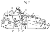
- the trigger 17 of the weapon is indicated is broken line in Figs. 2 and 3.
- the element of the servo trigger mechanism which acts on the gun trigger 17 is a pressure ramp 1.
- the ramp 1 is connected with the base plate 2 via a link connection having two link members 3 arranged mutually parallel to form a parallelogram linkage.
- the ramp 1 is liftable by the action of further link members 4 parallel with the link members 3.
- the link members 4 are parallel on common shafts, the uppermost of these shafts 4a being indicated in Figs. 2 and 3.
- the shaft 4a bears freely against one end of the ramp 1 as shown in Fig. 3.
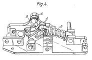
- a spring 5 (indicated in Fig. 4) coupled to the shaft 4a.
- the spring 5 is shown in a compressed position in Fig. 4, i.e. a position in which the shaft 4a is held down as disclosed in more detail below.
- the ramp 1 can be held in its raised position by engagement with a stop 7.
- the stop 7 is indicated most clearly in Fig. 3 in which it is seen in a disengaged position.
- the ramp 1 Before a first shot is fired, the ramp 1 is moved from its starting position, i.e. its raised position, to its lowered position, with the aid of a manual cocking arm of the weapon (not shown in the drawings), which may be of a conventional kind.
- This manual cocking arm is also lockable and, thus, acts as a safety means for the weapon.
- the cocking means may be alternatively another manual cocking mechanism or be electrically or hydraulically operated.
- the lowered position of the ramp 1 is its cocked position.
- the ramp 1 After firing of the first shot the ramp 1 will automatically be moved to its cocked position by the action of a cocking rod 8 (Fig. 5) which is operated by the gun recoil.
- the cocking rod 8 is acted on by a member (not shown) on the weapon that is moved to the right in Fig. 5 due to recoil movement and, to compress the spring 5 (Fig. 4) via link members 4, itself acts on a roller 9 on these link members.
- the counteracting force exerted by roller 9 is resisted by a second roller 10 mounted on an arm that is rigidly attached to the base plate 2.
- the rod 8 has a chamfered portion at the end area between the two rollers 9 and 10.
- the link members 4 In the recoil movement of the rod 8, the link members 4 are rotated rearwards and the ramp 1 on the parallelogram link members 3 is moved into its lowered position, i.e. its cocked position.
- the ramp 1 will remain in the cocked position due to the fact that the link members 4 are kept down by a trigger hook 11, friction and springs 15 - and 20, the hook 11 being in engagement with the shaft 4a. This holding action is shown in Fig. 2.
- the trigger hook 11 When a single shot is to be fired, the trigger hook 11 is retracted by a trigger rod 12 provided with a trigger (not shown).
- the trigger rod 12 is located in a support 13 which in turn is mounted on a shaft 14.
- Trigger hook 11 When its trigger is pulled, trigger rod 12 releases trigger hook 11 from the link shaft 4a.
- Trigger hook 11 is automatically moved forward by the spring force of a spring 20 shown in Fig. 2 to catch shaft 4a when the ramp 1 returns into its cocked position.
- the trigger hook per se is moved back into a position in which it is engaged with the shaft 4a by the spring 20.
- the trigger rod 12 is moved forward by spring 15 when its trigger is released.
- the device also comprises an automatic locking means in the form of the stop 7 indicated in Fig. 3.
- the stop 7 is used in connection with automatic firing and is operated by an arm 6.
- the arm 6 is locked in its forward position, which is shown in Fig. 3.
- the arm 6 is unlocked, the trigger rod 12 pulled back, and spring 15 pushes against the arm 6 (see Fig. 6).
- the spring 15, acting through the arm 6 has turned the stop 7 to a position with a surface 18 of the stop 7 in contact with a surface 18' on the ramp 1, which prevents the ramp 1 from falling down, the link members 4 being held in their lowered position by the trigger hook 11 after the firing of the first automatic shot.
- the gun trigger 17 is held in a permanent firing position without further movement of the ramp 1 and link members 4 and, thus, with reduced wear.
Landscapes
- Engineering & Computer Science (AREA)
- General Engineering & Computer Science (AREA)
- Portable Nailing Machines And Staplers (AREA)
- Toys (AREA)
- Spray Control Apparatus (AREA)
Claims (3)
Priority Applications (1)
| Application Number | Priority Date | Filing Date | Title |
|---|---|---|---|
| AT85308515T ATE41512T1 (de) | 1984-11-26 | 1985-11-22 | Servomechanik zum abfeuern von automatischen waffen. |
Applications Claiming Priority (2)
| Application Number | Priority Date | Filing Date | Title |
|---|---|---|---|
| NO844695 | 1984-11-26 | ||
| NO844695A NO155637C (no) | 1984-11-26 | 1984-11-26 | Anordning ved mekanisk servoavtrekkermekanisme for automatkanoner. |
Publications (2)
| Publication Number | Publication Date |
|---|---|
| EP0189647A1 EP0189647A1 (de) | 1986-08-06 |
| EP0189647B1 true EP0189647B1 (de) | 1989-03-15 |
Family
ID=19887957
Family Applications (1)
| Application Number | Title | Priority Date | Filing Date |
|---|---|---|---|
| EP85308515A Expired EP0189647B1 (de) | 1984-11-26 | 1985-11-22 | Servomechanik zum Abfeuern von automatischen Waffen |
Country Status (4)
| Country | Link |
|---|---|
| EP (1) | EP0189647B1 (de) |
| AT (1) | ATE41512T1 (de) |
| DE (1) | DE3568864D1 (de) |
| NO (1) | NO155637C (de) |
Families Citing this family (3)
| Publication number | Priority date | Publication date | Assignee | Title |
|---|---|---|---|---|
| AT388241B (de) * | 1986-07-17 | 1989-05-26 | Steyr Daimler Puch Ag | Ausloesevorrichtung zum abfeuern von maschinenkanonen |
| NO318101B1 (no) * | 1997-03-14 | 2005-01-31 | Vinghogs Mek Verksted As | Avtrekkssystem for rekyldrevne vapen |
| CN109269364B (zh) * | 2018-11-23 | 2023-09-12 | 中国人民解放军陆军工程大学 | 倒药装置 |
Family Cites Families (3)
| Publication number | Priority date | Publication date | Assignee | Title |
|---|---|---|---|---|
| DE712152C (de) * | 1936-03-11 | 1941-10-14 | Brandenburger Fahrrad Und Moto | Abzugseinrichtung fuer ruecklaufbeweglich lafettierte Maschinenwaffen |
| CH509563A (de) * | 1969-06-03 | 1971-06-30 | Oerlikon Buehrle Ag | Automatische Feuerwaffe |
| DE3001490C2 (de) * | 1980-01-17 | 1982-11-04 | Industrie-Werke Karlsruhe Augsburg AG Zweigniederlassung Keller & Knappich Augsburg, 8900 Augsburg | Mechanische Abzugsvorrichtung für Maschinenwaffen |
-
1984
- 1984-11-26 NO NO844695A patent/NO155637C/no unknown
-
1985
- 1985-11-22 AT AT85308515T patent/ATE41512T1/de not_active IP Right Cessation
- 1985-11-22 EP EP85308515A patent/EP0189647B1/de not_active Expired
- 1985-11-22 DE DE8585308515T patent/DE3568864D1/de not_active Expired
Also Published As
| Publication number | Publication date |
|---|---|
| NO844695L (no) | 1986-05-27 |
| NO155637B (no) | 1987-01-19 |
| ATE41512T1 (de) | 1989-04-15 |
| EP0189647A1 (de) | 1986-08-06 |
| DE3568864D1 (en) | 1989-04-20 |
| NO155637C (no) | 1987-04-29 |
Similar Documents
| Publication | Publication Date | Title |
|---|---|---|
| US6256918B1 (en) | Firing pin locking assembly for a semi-automatic handgun | |
| US5857280A (en) | Low pressure trigger pull with cocked position safety for a semiautomatic firearm | |
| US5349773A (en) | Double barrel break-action shotgun | |
| US2249231A (en) | Trigger mechanism | |
| EP0982557B1 (de) | Pistole mit Spannabzugseinrichtung | |
| US4680884A (en) | Safety firearm mechanism | |
| US5086578A (en) | Sear positioning spring for a firearm | |
| US4545143A (en) | Trigger mechanism for double barrel shotgun | |
| GB2195750A (en) | Gun with pivoting barrel and cocking mechanism | |
| CA2344147A1 (en) | Discharging device | |
| US4449312A (en) | Mechanism adaptable for single action revolvers | |
| US4625443A (en) | Single- or double-action tripping mechanism for four-barrelled pistols | |
| US5214233A (en) | Cocking and loading device for self-loading small firearms | |
| US4399628A (en) | Firing mechanism for firearms | |
| US3988848A (en) | Safety device for firearms | |
| EP0189647A1 (de) | Servomechanik zum Abfeuern von automatischen Waffen | |
| JP2694273B2 (ja) | 二連式銃のモノトリガ機構 | |
| US5705763A (en) | Fire selector system for selecting between automatic and semi-automatic operation of a gun | |
| FI80144C (fi) | Avtryckarmekanism foer laett tryck. | |
| US3183616A (en) | Selective one and two-stage trigger mechanism for firearms | |
| GB2327115A (en) | Transverse action breech block for a weapon | |
| US2186969A (en) | Machine gun structure | |
| US4315377A (en) | Single trigger firing of double barrel side-by-side or over-under firearms | |
| IT1202208B (it) | Meccanismo di percussione con dispositivo di sicurezza integrale | |
| US3459100A (en) | Mechanism for locking a missile retainer to a launching apparatus |
Legal Events
| Date | Code | Title | Description |
|---|---|---|---|
| PUAI | Public reference made under article 153(3) epc to a published international application that has entered the european phase |
Free format text: ORIGINAL CODE: 0009012 |
|
| AK | Designated contracting states |
Kind code of ref document: A1 Designated state(s): AT CH DE FR IT LI SE |
|
| 17P | Request for examination filed |
Effective date: 19870204 |
|
| 17Q | First examination report despatched |
Effective date: 19870924 |
|
| GRAA | (expected) grant |
Free format text: ORIGINAL CODE: 0009210 |
|
| AK | Designated contracting states |
Kind code of ref document: B1 Designated state(s): AT CH DE FR IT LI SE |
|
| REF | Corresponds to: |
Ref document number: 41512 Country of ref document: AT Date of ref document: 19890415 Kind code of ref document: T |
|
| ITF | It: translation for a ep patent filed | ||
| RAP2 | Party data changed (patent owner data changed or rights of a patent transferred) |
Owner name: NORSK FORSVARSTEKNOLOGI A/S |
|
| REF | Corresponds to: |
Ref document number: 3568864 Country of ref document: DE Date of ref document: 19890420 |
|
| ET | Fr: translation filed | ||
| PLBE | No opposition filed within time limit |
Free format text: ORIGINAL CODE: 0009261 |
|
| STAA | Information on the status of an ep patent application or granted ep patent |
Free format text: STATUS: NO OPPOSITION FILED WITHIN TIME LIMIT |
|
| 26N | No opposition filed | ||
| PGFP | Annual fee paid to national office [announced via postgrant information from national office to epo] |
Ref country code: SE Payment date: 19911030 Year of fee payment: 7 |
|
| PGFP | Annual fee paid to national office [announced via postgrant information from national office to epo] |
Ref country code: FR Payment date: 19911107 Year of fee payment: 7 |
|
| PGFP | Annual fee paid to national office [announced via postgrant information from national office to epo] |
Ref country code: AT Payment date: 19911112 Year of fee payment: 7 |
|
| PGFP | Annual fee paid to national office [announced via postgrant information from national office to epo] |
Ref country code: CH Payment date: 19911127 Year of fee payment: 7 |
|
| ITTA | It: last paid annual fee | ||
| PGFP | Annual fee paid to national office [announced via postgrant information from national office to epo] |
Ref country code: DE Payment date: 19911230 Year of fee payment: 7 |
|
| PG25 | Lapsed in a contracting state [announced via postgrant information from national office to epo] |
Ref country code: AT Effective date: 19921122 |
|
| PG25 | Lapsed in a contracting state [announced via postgrant information from national office to epo] |
Ref country code: SE Effective date: 19921123 |
|
| PG25 | Lapsed in a contracting state [announced via postgrant information from national office to epo] |
Ref country code: LI Effective date: 19921130 Ref country code: CH Effective date: 19921130 |
|
| PG25 | Lapsed in a contracting state [announced via postgrant information from national office to epo] |
Ref country code: FR Effective date: 19930730 |
|
| REG | Reference to a national code |
Ref country code: CH Ref legal event code: PL |
|
| PG25 | Lapsed in a contracting state [announced via postgrant information from national office to epo] |
Ref country code: DE Effective date: 19930803 |
|
| REG | Reference to a national code |
Ref country code: FR Ref legal event code: ST |
|
| EUG | Se: european patent has lapsed |
Ref document number: 85308515.7 Effective date: 19930610 |