EP0189770A2 - Cassette de ruban encreur pour dispositifs d'impression électrothermique imprimant sans frappe des signes matriciels à points - Google Patents
Cassette de ruban encreur pour dispositifs d'impression électrothermique imprimant sans frappe des signes matriciels à points Download PDFInfo
- Publication number
- EP0189770A2 EP0189770A2 EP86100342A EP86100342A EP0189770A2 EP 0189770 A2 EP0189770 A2 EP 0189770A2 EP 86100342 A EP86100342 A EP 86100342A EP 86100342 A EP86100342 A EP 86100342A EP 0189770 A2 EP0189770 A2 EP 0189770A2
- Authority
- EP
- European Patent Office
- Prior art keywords
- cleaning
- ink ribbon
- ribbon
- printing
- electrodes
- Prior art date
- Legal status (The legal status is an assumption and is not a legal conclusion. Google has not performed a legal analysis and makes no representation as to the accuracy of the status listed.)
- Withdrawn
Links
Images
Classifications
-
- B—PERFORMING OPERATIONS; TRANSPORTING
- B41—PRINTING; LINING MACHINES; TYPEWRITERS; STAMPS
- B41J—TYPEWRITERS; SELECTIVE PRINTING MECHANISMS, i.e. MECHANISMS PRINTING OTHERWISE THAN FROM A FORME; CORRECTION OF TYPOGRAPHICAL ERRORS
- B41J32/00—Ink-ribbon cartridges
-
- B—PERFORMING OPERATIONS; TRANSPORTING
- B41—PRINTING; LINING MACHINES; TYPEWRITERS; STAMPS
- B41J—TYPEWRITERS; SELECTIVE PRINTING MECHANISMS, i.e. MECHANISMS PRINTING OTHERWISE THAN FROM A FORME; CORRECTION OF TYPOGRAPHICAL ERRORS
- B41J29/00—Details of, or accessories for, typewriters or selective printing mechanisms not otherwise provided for
- B41J29/17—Cleaning arrangements
Definitions
- the invention relates to an ink ribbon cassette for an electrothermal printing device for the non-stop printing of dot matrix characters on a recording medium of the type specified in the preamble of claim 1.
- the invention has for its object to provide an ink ribbon cassette for an electrothermal printing device for the non-stop printing of dot matrix characters on a recording medium by means of an electrically conductive ink ribbon, with which a simple automatic cleaning of the print head with the recording electrodes is possible in such a way that printing from on the Recording medium sharply delimited points is always guaranteed.
- This object is achieved by the invention characterized in claim 1.
- each ink ribbon has at least one section covered with cleaning material, there is always an automatic cleaning of the recording electrodes after a certain number of printing processes. In this way, the generation of records with high font quality is always guaranteed. Due to the advantageous embodiment of the subject matter of the invention, the recording electrodes are always cleaned before the use of a new ink ribbon.
- the supply spool and the take-up spool with the ink ribbon are advantageously arranged in an ink ribbon cassette. It is no longer necessary to replace an ink ribbon cassette with an ink ribbon without a cleaning section for a cartridge with a cleaning tape.
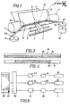
- FIG. 1 shows an electrothermal printing device for the non-stop printing of dot matrix characters on a recording medium 1 by means of an electrically conductive ink ribbon 2, the color particles of which are solid at room temperature and, after heating to a threshold temperature, have melted and adhere to the recording medium 1.
- the record carrier 1 can be transported by a platen roller 3, which can be driven by a stepping motor, not shown.
- the ribbon 2 consists according to Figure 5 z. B.
- the print head 7 presses the ink ribbon 2 against the recording medium 1, which supports the adhesion of the melted ink 4 on the recording medium 1.
- the carriage 4 with the print head 7 is advanced column by column to generate dot matrix characters.
- the ink ribbon 2 is unwound from a supply spool 14 according to FIG. 1 with the aid of a device customary in typewriters and rewound onto a take-up spool 15, the ink ribbon 2 being guided along deflection pins 16, 17 along the recording medium 1 at a close distance from the latter.
- the supply reel 14 and the take-up reel 15 are rotatably mounted outside the printing area in the frame, the take-up reel 15 being driven by a drive motor 18 for transporting the ink ribbon 2 for an entire line. Since the recording electrodes 8 and the counterelectrode 12 on the printhead 7 become dirty due to friction on the recording medium 1 or due to other dust, the ink ribbon according to FIG.
- FIG. 4 shows an ink ribbon 21 with at least one section 22 arranged transversely to its longitudinal direction, which is covered with cleaning material on its side facing the recording electrodes 8.
- This section 22 may e.g. B. in the middle of the longitudinal direction of the ink ribbon 21 or on the core 23 of the supply reel 14 as a trailing ribbon.
- the transition point from the ink ribbon 21 to the section 22 covered with cleaning material must, however, be monitored by a scanning device in such a way that no pressure pulses are lost for the generation of dot matrix characters.
- This ink ribbon 21 also produces a cleaning of the printhead 7 which can be triggered automatically at certain time intervals.
- the ink ribbon 24 according to FIG. 3 can also have two fields 25, 26 divided in the longitudinal direction, of which one field 25 has a color layer facing the recording medium 1 and the other field 26 has a layer of cleaning material facing the recording electrodes 8.
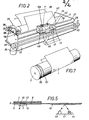
- FIG. 2 shows an electrothermal printing device which shows a carriage 29 which can be moved along the recording medium 1 on guide axes 27, 28 and on which the print head 7 with the recording electrodes 8 of the counterelectrode 12 is pivotably mounted.
- the print head 7 lies against the recording medium 1 during the printing process, while it is lifted in a known manner during non-printing processes in order to avoid unnecessary wear of the print head 7.
- the ends of a belt 30 are fastened to the carriage 29 and are deflected on the one hand by a deflection roller 31 and on the other hand by a drive roller 32 in the frame 33.
- the driving role 32 is in drive connection with a stepper motor 34.
- the record carrier 1 can be driven by a stepper motor 35 via a belt drive 36, 37, 38.
- a supply reel 39 and a take-up reel 40 are rotatably mounted in an ink ribbon cassette 42 that can be placed on a holding device 41 of the carriage 29.
- the ribbon 43 of this ribbon cassette 42 has, for. B. a with the core of the take-up reel 40 leader tape 59 with a cleaning material.
- the ribbon cassette 42 is provided with control means, by means of which control elements in the printing device can be acted upon.
- the receiving device 41 can have a scanning device for the ink ribbon 43, by means of which a program for an automatic cleaning of the print head 7 can be triggered when a section with cleaning material is detected on the ink ribbon 43.
- the scanning device can consist of optical sensing elements with a light transmitter 44 and a light receiver 45.
- the scanning device can consist of the print head 7 and the counterelectrode 12, which act like contact elements, scan the surface of the ink ribbon 43 and which are electrically connected to the printing group control and / or function or fault display.
- the controls may also be responsive to contact with the bottom 46 of the ribbon cartridge 42 electrical switches, e.g. B. a microswitch 47 according to FIG. 2. If the microswitch 47 is pivoted from the dashed to the solid representation when the ink ribbon cassette 42 is placed on the receiving device 41, the circuit is closed to a special key 49 arranged in the keyboard 48, see FIG. 6. By actuating this special key 49, trigger pulses are applied to a Given control 50, which, for. B. can be a microprocessor.
- This control element 50 gives drive pulses via an amplifier 51 to an electromagnet 52 for pivoting the print head 7 in pressure contact contact with the recording medium 1 and the platen roller 3, the electrodes 8 and 12 lie on the section with the cleaning material.
- control element 50 transmits drive pulses via amplifiers 53, 54 to the stepper motors 34, 55 for the carriage 29 and the take-up spool 40.
- the ink ribbon released by the supply spool 39 is rewound by the take-up spool 40 by means of the stepper motor 55.
- the print head 7 slides smoothly over the surface of the cleaning material in such a way that the free end faces of the electrodes 8 are cleaned and ground smooth.
- This cleaning process is ended when the ink ribbon with the ink layer has reached the point of printing.
- the print head 7 is pivoted into the lift-off position and the ink ribbon is again transported so far that the ink layer is now in the area of the print head 7.
- the cleaning process is now complete and the printing process can now begin with a cleaned print head 7. In this way, clean dot matrix characters are always generated on the recording medium 1.
- the bottom surface 46 of the ink ribbon cassette 42 can have a membrane, which initially closes the switch 47, but is released when the ink ribbon cassette 42 is locked on the receiving device 41, thereby destroying the membrane. This prevents the switch 47 from being acted upon again when a ribbon cassette 42 that has already been used is inserted.
- the cleaning element can consist of a cleaning pad 56 arranged outside the platen roller 3 transporting the recording medium 1.
- the platen roller 3 transporting the recording medium 1 can also have a circumferential depression which is arranged outside the printing area and is filled by a cleaning strip 57 designed as a cleaning element, see FIG. 7.
- the printing roller 3 is compared to the one with the cleaning strip 57 in contact electrodes 8 of the printhead 7 rotated.
- the surface of the print head 7 is ground in such a way that the electrodes 8 are clean and sharp-edged again.
- the ribbon cassette 42 must be removed, and the control for triggering a cleaning process can be carried out automatically by removing the ribbon cassette 42. This makes it possible to clean the print head, which is dusty or dirty after a long period of non-use, even if the ink ribbon cassette has not yet been written completely empty.
- the cleaning process of the print head 7 can also be switched off if the print head 7 and the counter electrode 12 come into contact with the electrically conductive ink ribbon after leaving the cleaning section.
- the ribbon end can also be displayed via these contacting elements 7, 12.
Landscapes
- Impression-Transfer Materials And Handling Thereof (AREA)
- Accessory Devices And Overall Control Thereof (AREA)
- Electronic Switches (AREA)
Applications Claiming Priority (2)
| Application Number | Priority Date | Filing Date | Title |
|---|---|---|---|
| DE3502725 | 1985-01-28 | ||
| DE19853502725 DE3502725A1 (de) | 1985-01-28 | 1985-01-28 | Elektrothermische druckvorrichtung zum anschlaglosen drucken von punktmatrixzeichen |
Publications (2)
| Publication Number | Publication Date |
|---|---|
| EP0189770A2 true EP0189770A2 (fr) | 1986-08-06 |
| EP0189770A3 EP0189770A3 (fr) | 1988-07-06 |
Family
ID=6260939
Family Applications (1)
| Application Number | Title | Priority Date | Filing Date |
|---|---|---|---|
| EP86100342A Withdrawn EP0189770A3 (fr) | 1985-01-28 | 1986-01-13 | Cassette de ruban encreur pour dispositifs d'impression électrothermique imprimant sans frappe des signes matriciels à points |
Country Status (3)
| Country | Link |
|---|---|
| EP (1) | EP0189770A3 (fr) |
| JP (1) | JPS61222783A (fr) |
| DE (1) | DE3502725A1 (fr) |
Cited By (1)
| Publication number | Priority date | Publication date | Assignee | Title |
|---|---|---|---|---|
| US5037216A (en) * | 1988-09-23 | 1991-08-06 | Datacard Corporation | System and method for producing data bearing cards |
Families Citing this family (2)
| Publication number | Priority date | Publication date | Assignee | Title |
|---|---|---|---|---|
| JPS6440662U (fr) * | 1987-09-04 | 1989-03-10 | ||
| DE102004050379A1 (de) * | 2004-10-15 | 2006-04-27 | Avery Dennison Corp., Pasadena | Etikettendrucksystem mit austauschbarer Reinigungswalze |
Family Cites Families (2)
| Publication number | Priority date | Publication date | Assignee | Title |
|---|---|---|---|---|
| GB1390187A (en) * | 1971-05-14 | 1975-04-09 | Barron R M | Method of cleaning printing type |
| FR2190060A5 (fr) * | 1972-06-19 | 1974-01-25 | Honeywell Bull |
-
1985
- 1985-01-28 DE DE19853502725 patent/DE3502725A1/de not_active Withdrawn
-
1986
- 1986-01-13 EP EP86100342A patent/EP0189770A3/fr not_active Withdrawn
- 1986-01-27 JP JP61013950A patent/JPS61222783A/ja active Pending
Cited By (3)
| Publication number | Priority date | Publication date | Assignee | Title |
|---|---|---|---|---|
| US5037216A (en) * | 1988-09-23 | 1991-08-06 | Datacard Corporation | System and method for producing data bearing cards |
| US5401111A (en) * | 1988-09-23 | 1995-03-28 | Datacard Corporation | System and method for cleaning data bearing cards |
| US5588763A (en) * | 1988-09-23 | 1996-12-31 | Datacard Corporation | System and method for cleaning and producing data bearing cards |
Also Published As
| Publication number | Publication date |
|---|---|
| JPS61222783A (ja) | 1986-10-03 |
| EP0189770A3 (fr) | 1988-07-06 |
| DE3502725A1 (de) | 1986-09-18 |
Similar Documents
| Publication | Publication Date | Title |
|---|---|---|
| DE2315226C3 (de) | Aufzeichnungsvorrichtung | |
| DE3145221C2 (de) | Verfahren und Vorrichtung zur Steuerung der Transporteinrichtung für das Farbband in Wärmedruckvorrichtungen | |
| EP0730974B1 (fr) | Dispositif et cartouche à ruban encreur pour l'impression par transfert thermique | |
| DE3108367C2 (de) | Verfahren zur Steuerung der Bewegung zwischen dem Thermokopf und einem Aufzeichnungsmaterial in einer Thermodruckvorrichtung | |
| DD233101B5 (de) | Postfrankiermaschine | |
| DE2434626C3 (de) | Elektronischer Taschenrechner | |
| EP0195949B1 (fr) | Imprimante à un ou plusieurs postes d'impression | |
| DE3026438A1 (de) | Schlaglosdruckvorrichtung und -verfahren | |
| EP0099120B1 (fr) | Dispositif universel d'alimentation de papier pour feuilles et bandes dans une imprimante ligne pour ligne | |
| DE3119025A1 (de) | Thermodrucker | |
| DE2232590B2 (de) | Schreibeinrichtung zum Abdrucken von Zeichen | |
| DE3502535C2 (fr) | ||
| DE1512401B2 (de) | Verfahren und Einrichtung zur elektrographischen Aufzeichnung | |
| EP0189770A2 (fr) | Cassette de ruban encreur pour dispositifs d'impression électrothermique imprimant sans frappe des signes matriciels à points | |
| DE69019813T2 (de) | Aufzeichnungsgerät. | |
| DE3614841C2 (fr) | ||
| DE3146242C2 (fr) | ||
| DE2642069C2 (de) | Vorrichtung zum Längstransport einmalig verwendbarer Farb- oder Löschbänder in kraftangetriebenen Schreib- oder ähnlichen Büromaschinen | |
| DE69503996T2 (de) | Vorrichtung zur erkennung einer erschöpfung des tintenvorrates und tintenstrahldrucker | |
| DE1088071B (de) | Tabuliereinrichtung an Schreibmaschinen | |
| DE3705950C2 (fr) | ||
| DE3421406C1 (de) | Farbbandkassette fuer Schreib- oder aehnliche Maschinen | |
| DE1242912B (de) | Elektrographische Druckeinrichtung | |
| DE2705328A1 (de) | Tintenschreibwerk | |
| EP0116943A2 (fr) | Dispositif à impression matricielle pour étiquettes de marchandise, en particulier balance avec délivrance d'étiquettes |
Legal Events
| Date | Code | Title | Description |
|---|---|---|---|
| PUAI | Public reference made under article 153(3) epc to a published international application that has entered the european phase |
Free format text: ORIGINAL CODE: 0009012 |
|
| AK | Designated contracting states |
Kind code of ref document: A2 Designated state(s): CH DE FR GB LI SE |
|
| RAP1 | Party data changed (applicant data changed or rights of an application transferred) |
Owner name: AEG OLYMPIA AKTIENGESELLSCHAFT |
|
| PUAL | Search report despatched |
Free format text: ORIGINAL CODE: 0009013 |
|
| RHK1 | Main classification (correction) |
Ipc: B41J 31/05 |
|
| AK | Designated contracting states |
Kind code of ref document: A3 Designated state(s): CH DE FR GB LI SE |
|
| 17P | Request for examination filed |
Effective date: 19880826 |
|
| RAP1 | Party data changed (applicant data changed or rights of an application transferred) |
Owner name: AEG OLYMPIA OFFICE GMBH |
|
| 17Q | First examination report despatched |
Effective date: 19900111 |
|
| STAA | Information on the status of an ep patent application or granted ep patent |
Free format text: STATUS: THE APPLICATION HAS BEEN WITHDRAWN |
|
| 18W | Application withdrawn |
Withdrawal date: 19901115 |
|
| R18W | Application withdrawn (corrected) |
Effective date: 19901115 |
|
| RIN1 | Information on inventor provided before grant (corrected) |
Inventor name: KONRAD, RUDI |