EP0189828A2 - Transporteur à chaînes pour le dispositif de sortie des machines à imprimer - Google Patents
Transporteur à chaînes pour le dispositif de sortie des machines à imprimer Download PDFInfo
- Publication number
- EP0189828A2 EP0189828A2 EP86100746A EP86100746A EP0189828A2 EP 0189828 A2 EP0189828 A2 EP 0189828A2 EP 86100746 A EP86100746 A EP 86100746A EP 86100746 A EP86100746 A EP 86100746A EP 0189828 A2 EP0189828 A2 EP 0189828A2
- Authority
- EP
- European Patent Office
- Prior art keywords
- gripper
- chain conveyor
- conveyor according
- base body
- gripper system
- Prior art date
- Legal status (The legal status is an assumption and is not a legal conclusion. Google has not performed a legal analysis and makes no representation as to the accuracy of the status listed.)
- Granted
Links
- 238000007639 printing Methods 0.000 title claims abstract description 12
- XAGFODPZIPBFFR-UHFFFAOYSA-N aluminium Chemical compound [Al] XAGFODPZIPBFFR-UHFFFAOYSA-N 0.000 claims abstract description 40
- 229910052782 aluminium Inorganic materials 0.000 claims abstract description 40
- 229910000831 Steel Inorganic materials 0.000 claims abstract description 16
- 239000010959 steel Substances 0.000 claims abstract description 16
- 230000005484 gravity Effects 0.000 claims abstract description 4
- 239000004033 plastic Substances 0.000 claims description 10
- 238000005452 bending Methods 0.000 claims description 2
- 239000002991 molded plastic Substances 0.000 claims description 2
- 230000002349 favourable effect Effects 0.000 claims 1
- 238000005266 casting Methods 0.000 description 7
- 238000010137 moulding (plastic) Methods 0.000 description 4
- 239000013585 weight reducing agent Substances 0.000 description 3
- 238000004519 manufacturing process Methods 0.000 description 2
- 239000000463 material Substances 0.000 description 2
- 229910001208 Crucible steel Inorganic materials 0.000 description 1
- 238000004026 adhesive bonding Methods 0.000 description 1
- 238000001816 cooling Methods 0.000 description 1
- 238000009826 distribution Methods 0.000 description 1
- 238000005553 drilling Methods 0.000 description 1
- 230000000694 effects Effects 0.000 description 1
- 238000010438 heat treatment Methods 0.000 description 1
- 238000003780 insertion Methods 0.000 description 1
- 230000037431 insertion Effects 0.000 description 1
- 238000003754 machining Methods 0.000 description 1
- 238000000034 method Methods 0.000 description 1
- 230000008092 positive effect Effects 0.000 description 1
Images


Classifications
-
- B—PERFORMING OPERATIONS; TRANSPORTING
- B65—CONVEYING; PACKING; STORING; HANDLING THIN OR FILAMENTARY MATERIAL
- B65H—HANDLING THIN OR FILAMENTARY MATERIAL, e.g. SHEETS, WEBS, CABLES
- B65H29/00—Delivering or advancing articles from machines; Advancing articles to or into piles
- B65H29/02—Delivering or advancing articles from machines; Advancing articles to or into piles by mechanical grippers engaging the leading edge only of the articles
- B65H29/04—Delivering or advancing articles from machines; Advancing articles to or into piles by mechanical grippers engaging the leading edge only of the articles the grippers being carried by endless chains or bands
- B65H29/041—Delivering or advancing articles from machines; Advancing articles to or into piles by mechanical grippers engaging the leading edge only of the articles the grippers being carried by endless chains or bands and introducing into a pile
-
- B—PERFORMING OPERATIONS; TRANSPORTING
- B65—CONVEYING; PACKING; STORING; HANDLING THIN OR FILAMENTARY MATERIAL
- B65H—HANDLING THIN OR FILAMENTARY MATERIAL, e.g. SHEETS, WEBS, CABLES
- B65H29/00—Delivering or advancing articles from machines; Advancing articles to or into piles
- B65H29/02—Delivering or advancing articles from machines; Advancing articles to or into piles by mechanical grippers engaging the leading edge only of the articles
- B65H29/04—Delivering or advancing articles from machines; Advancing articles to or into piles by mechanical grippers engaging the leading edge only of the articles the grippers being carried by endless chains or bands
- B65H29/045—Details of grippers
-
- B—PERFORMING OPERATIONS; TRANSPORTING
- B65—CONVEYING; PACKING; STORING; HANDLING THIN OR FILAMENTARY MATERIAL
- B65H—HANDLING THIN OR FILAMENTARY MATERIAL, e.g. SHEETS, WEBS, CABLES
- B65H2801/00—Application field
- B65H2801/03—Image reproduction devices
- B65H2801/21—Industrial-size printers, e.g. rotary printing press
Definitions
- the invention relates to chain conveyors for the delivery arm of printing machines, in which the gripper systems are carried by endless transport chains, the gripper systems being fastened to the transport chain by means of connecting lugs which are fastened to the transport chain by means of bolts.
- a wide variety of chain conveyors have become known, e.g. under DE-OS 2 424 917 a chain conveyor which is carried directly by endless chains and which each carry four adjacent bolts of four successive chain roller bolts, each of which has a common connecting link, each of which has an axis parallel to the chain bolts and directed towards the center of the machine and carrying the gripper system is.
- the gripper system consists of a gripper shaft and a support tube. Individual gripper pads are attached to the support tube. The gripper pads are fastened by screwing. Furthermore, bearings for guiding and holding the gripper shaft are provided on the support tube, these being fastened with pins. The assembly of these gripper pads and bearings on the support tube was very complex and therefore very expensive. Mainly through the precise alignment and adjustment of these many individual parts. Furthermore, the screw connections could loosen after some operating time if they had not been screwed or secured properly.
- the invention has for its object to provide a chain conveyor that is torsionally rigid and rigid and in the deflection area of the Chain conveyor has low inertial forces even at high machine speeds.
- the gripper system is formed from a one-piece aluminum base body, that the aluminum base body has sprue points that a cast steel tube is arranged approximately in the center of gravity of the aluminum body over its entire length that the steel tube is approximately the same distance from the outer shell of the aluminum base body, and that the moments of inertia are adapted to the main load levels in which the long underside of the trapezoidal aluminum base body is arranged opposite the force-absorbing side with the sprue points.
- the gripper system is made of a one-piece aluminum body.
- the material aluminum significantly reduces the total weight. Due to the shape of the gripper system, the deflection and twisting has significantly improved with the mentioned weight reduction.
- the outer shape of the gripper system is chosen so that, with given dimensions and functions of the gripper system, optimum bending and torsional rigidity has been achieved with a minimal weight.
- the aluminum hollow profile is self-contained and adapted with its area moment of inertia to the main load level. This is achieved by arranging the long underside of the trapezoidal aluminum body opposite the force-absorbing side with the sprue points, here the gripper pads. This also optimally absorbs the forces that occur during the deflection of the gripper systems, as well as the torsional forces that act on the gripper systems from the roller levers.
- the design of the shape of the gripper system takes into account the necessary freedom from shadows, so that the use of dryers can be used on the printing press. Since the bearing of the gripper shaft is cast onto the aluminum base body, the rigidity of the gripper system increases again.
- the aluminum base body has sprue points which are used for the bearing points of the gripper shaft and for the gripper pads.
- the simple processing of the aluminum body in two steps leads to the above-mentioned simplification of assembly.
- a cast-in steel tube is arranged in the center of gravity of the aluminum body over its entire length.
- sand core production could be dispensed with.
- the structure of the entire casting is optimally evened out by the shape, that is to say the approximately the same wall thicknesses over the entire length of the casting.
- the steel pipe is literally shrunk on in the casting after cooling, since the coefficient of expansion of aluminum is significantly larger than the coefficient of expansion of steel. A loosening of the steel pipe is not possible even with long operating times.
- the hollow shape increases the rigidity by a substantial amount compared to a full shape.
- the above-mentioned weight reduction also has a particularly positive effect on the overall behavior of the printing press due to optimal, smooth running, especially at high press speeds.
- the above-mentioned weight reduction due to the shape and the choice of materials in aluminum enable the printing press with the maximum speeds required today, i.e. more than 10,000 b / h, without the gripper systems not being able to cope with the deflection area, the resulting centrifugal forces and the resulting loads.
- the gate points are gripper pads.
- the shape of the gripper pads is chosen so that the plastic molded parts are used in the direction of the gripper closing movement, so that falling out or loosening of the plastic molded parts is not possible, since the closing movement of the gripper repeatedly pushes the plastic molded parts into their secured end positions.
- the plastic molded parts have a central semicircular guide, which achieves the optimum folding effect with easy assembly.
- the gripper shaft is preloaded by a torsion bar split in the middle.
- the two roller levers are evenly loaded by this simple measure.
- the torsion bar spring is held by a special Opening in the gripper shaft and screwed to the aluminum body.
- An angle bracket is attached to the transport chain to connect the gripper systems as a connecting link.
- the one-piece aluminum body is assembled by simply screwing both ends of the aluminum body onto the angle of the transport chain with two screws each.
- the gripper systems can be replaced simply by loosening the screws.
- the chains are firmly arranged in the lateral guide of the printing machine during assembly of the aluminum base body, so the chains are not open, which would make assembly of the gripper systems considerably more difficult.
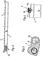
- a gripper system 1 for the delivery of a printing machine is shown.
- the gripper system 1 is held on a transport chain 2 by means of bolts 3.
- the transport chain 2 is locked in the areas in which the gripper systems 1 are provided by means of connecting straps 4.
- an angle 5 is fastened to the transport chain 2 by means of the bolts 3.
- On the other side of the transport chain 2 there is the connecting link 4 opposite, which are also locked with the bolts 3 on the transport chain 2.
- the connecting link 4 and the angle 5 are thus firmly anchored in the transport chain 2 by the bolts 3.
- the gripper system 1 is mounted in the printing press by screwing it onto the angles 5 with screws 13, 14.
- the transport chain 2 is particularly easily closed during the assembly process.
- the fitter fastens a gripper system 1 and then moves the transport chain 2 only by a partial amount up to the next angle 5 half of the transport chain 2 and screwed the next gripper system 1 to the angle 5 with the screws 13, 14.
- the gripper system 1 is thus optimally held at both ends with the angles 5 and the assembly can be carried out with the transport chain 2 closed.
- the gripper system 1 is formed from a one-piece aluminum base body 6.
- the assembly time of the gripper system 1 is reduced considerably due to the one-piece aluminum base body 6.
- the aluminum base body 6 is shown in its side length in its entire length.
- a steel tube 9 is arranged in the interior of the aluminum base body 6.
- the steel tube 9 significantly increases the rigidity of the aluminum base body 6.
- the aluminum base body 6 has sprue points 7 which can be brought to their final shape with machines in one operation after the casting process. The sprue 7 are thus casting after the production of the raw shape of the aluminum base body 6, which can be machined inexpensively in one operation.
- the gate 8 is a bearing 10 for a gripper shaft 11.
- the bearing 10 is produced with a tool aligned over the entire length of the gripper system 1, i.e. one side of the gripper system 1 is open in order to be able to install the gripper shaft 11 on one side and the opposite side on the gripper system 1 is closed. The open side is closed on the front side after the insertion of the gripper shaft 11 with a closure part 12.
- the sprue 7 on the aluminum base body 6 of the gripper system 1 is shown in detail.
- a semicircular web 17 is milled into the sprue 7, in which a counter-profile in the form of a plastic molded part 16 is then inserted and glued.
- the plastic molding 16 is the gripper pad and the gripper, not shown, cannot loosen the plastic molding 16 because the pushing movement of the gripper presses the plastic molding 16 against an end stop of a holder 15.
- the plastic molded part 16 is formed at right angles and lies on the holder 15 with the rectangular outer shape.
- the rectangular support, the semicircular web 17 and the gluing of the plastic molded part 16 leads to an inseparable gripper pad.
- FIG. 5 shows the top view of the gripper system 1 with the gripper shaft 11 used.
- the gripper shaft 11 is held in the bearings 10.
- the bearings 10 are produced in one operation by drilling out the sprue 8.
- the sprue 8 additionally stiffen the aluminum base body 6.
- the illustration shows the distribution of the sprue points 7 on the aluminum base body 6.
- the holders 15 for the gripper pads, the plastic molded parts 16, can be produced by simple machining of the sprue points 7.
- the gripper system 1 is screwed at its two lateral ends with the screws 13, 14 to the angles 5 of the transport chain 2.
- the trapezoidal aluminum base body 6 is shown.
- the area moments of inertia are adapted to the main load levels by the choice of shape.
- Central inside is the cast-in steel tube 9.
- the deflection and twisting of the gripper system 1 can be substantially improved by this shape and design as a hollow form with an inserted steel tube 9.
Landscapes
- Engineering & Computer Science (AREA)
- Mechanical Engineering (AREA)
- Discharge By Other Means (AREA)
- Feeding Of Articles By Means Other Than Belts Or Rollers (AREA)
- Delivering By Means Of Belts And Rollers (AREA)
- Adornments (AREA)
- Inking, Control Or Cleaning Of Printing Machines (AREA)
- Casings For Electric Apparatus (AREA)
Priority Applications (1)
| Application Number | Priority Date | Filing Date | Title |
|---|---|---|---|
| AT86100746T ATE53816T1 (de) | 1985-01-26 | 1986-01-21 | Kettenfoerderer fuer den ausleger von druckmaschinen. |
Applications Claiming Priority (2)
| Application Number | Priority Date | Filing Date | Title |
|---|---|---|---|
| DE3502663A DE3502663C1 (de) | 1985-01-26 | 1985-01-26 | Kettenfoerderer fuer den Ausleger von Druckmaschinen |
| DE3502663 | 1985-01-26 |
Publications (3)
| Publication Number | Publication Date |
|---|---|
| EP0189828A2 true EP0189828A2 (fr) | 1986-08-06 |
| EP0189828A3 EP0189828A3 (en) | 1988-04-27 |
| EP0189828B1 EP0189828B1 (fr) | 1990-05-02 |
Family
ID=6260880
Family Applications (1)
| Application Number | Title | Priority Date | Filing Date |
|---|---|---|---|
| EP86100746A Expired - Lifetime EP0189828B1 (fr) | 1985-01-26 | 1986-01-21 | Transporteur à chaînes pour le dispositif de sortie des machines à imprimer |
Country Status (6)
| Country | Link |
|---|---|
| US (1) | US4693362A (fr) |
| EP (1) | EP0189828B1 (fr) |
| JP (1) | JPH0735215B2 (fr) |
| AT (1) | ATE53816T1 (fr) |
| BR (1) | BR8600481A (fr) |
| DE (1) | DE3502663C1 (fr) |
Cited By (1)
| Publication number | Priority date | Publication date | Assignee | Title |
|---|---|---|---|---|
| EP0669210A1 (fr) * | 1994-01-26 | 1995-08-30 | ORMAG S.p.A. | Dispositif de montage pour les barres supportant les pinces dans des machines pour imprimer des cartes ou des papiers-valeur |
Families Citing this family (14)
| Publication number | Priority date | Publication date | Assignee | Title |
|---|---|---|---|---|
| DE3701103A1 (de) * | 1987-01-16 | 1988-07-28 | Roland Man Druckmasch | Vorrichtung zum transport von in einer druckmaschine bedruckten bogen mittels kettenuebergabesystemen |
| US4915283A (en) * | 1988-10-06 | 1990-04-10 | Curwood, Inc. | Clamping arrangement for gripping and carrying web material |
| DE3939250C1 (fr) * | 1989-11-28 | 1990-12-13 | Miller-Johannisberg Druckmaschinen Gmbh, 6222 Geisenheim, De | |
| JPH06100197A (ja) * | 1992-09-21 | 1994-04-12 | Xerox Corp | シート掴み機構 |
| US5383326A (en) * | 1993-11-24 | 1995-01-24 | Premark Feg Corporation | Sheet material gripping system |
| CH690097A5 (fr) * | 1994-05-04 | 2000-04-28 | Bobst Sa | Dispositif d'attache d'une barre de pinces à un train de chaînes au sein d'une machine de traitement d'éléments en plaque. |
| CH690098A5 (fr) * | 1994-05-04 | 2000-04-28 | Bobst Sa | Barre de pinces comportant un dispositif d'attache à un train de chaînes au sein d'une machine de traitement d'éléments en plaque. |
| DE19513420A1 (de) * | 1995-04-08 | 1996-10-10 | Heidelberger Druckmasch Ag | Kettentrieb |
| DE19527439C2 (de) * | 1995-07-27 | 2002-10-24 | Heidelberger Druckmasch Ag | Greiferbrücke für Ausleger von Druckmaschinen |
| US6786482B2 (en) * | 2001-02-01 | 2004-09-07 | Hallmark Cards Incorporated | Material handler apparatus |
| DE102008011052C5 (de) * | 2007-03-22 | 2019-08-01 | Heidelberger Druckmaschinen Ag | Vorrichtung zum Transport von Bogen mittels einer kettengetriebenen Greiferbrücke |
| CN109368108B (zh) * | 2018-11-09 | 2024-05-28 | 武汉锦隆工程技术有限公司 | 一种用于炼钢精炼区域测温取样自动料库的装置 |
| DE102023109057A1 (de) | 2023-04-11 | 2024-10-17 | Koenig & Bauer Ag | Vorrichtung zum Transport von Bogen |
| DE102023109056A1 (de) | 2023-04-11 | 2024-10-17 | Koenig & Bauer Ag | Vorrichtung zum Transport von Bogen |
Family Cites Families (14)
| Publication number | Priority date | Publication date | Assignee | Title |
|---|---|---|---|---|
| US2024140A (en) * | 1934-04-23 | 1935-12-17 | Christensen Machine Co | Sheet gripping device |
| US2756995A (en) * | 1950-03-30 | 1956-07-31 | Roland Offsetmaschf | Sheet transferring device for multiunit printing machines |
| US2827292A (en) * | 1951-03-22 | 1958-03-18 | Roland Offsetmaschf | Printing machine mechanism |
| US2882049A (en) * | 1955-03-12 | 1959-04-14 | Roland Offsetmaschf | Gripper for use in printing machines |
| US2984178A (en) * | 1956-03-07 | 1961-05-16 | Roland Offsetmaschf | Gripper for use in printing machines |
| DE1232595B (de) * | 1966-06-01 | 1967-01-19 | Roland Offsetmaschf | Greifervorrichtung an Bogenfoerdervorrichtungen |
| CH483926A (de) * | 1968-02-28 | 1970-01-15 | Roland Offsetmaschf | Vorrichtung zur passgerechten Bogenübergabe an Druckwerken |
| DE2157993C2 (de) * | 1971-11-23 | 1974-01-31 | Roland Offsetmaschinenfabrik Faber & Schleicher Ag, 6050 Offenbach | Vorrichtung zum Transport von Bogen in einer Bogendruckmaschine |
| DE2246061B1 (de) * | 1972-09-20 | 1973-10-18 | Roland Offsetmaschinenfabrik Faber & Schleicher Ag, 6050 Offenbach | Greiferwagen-Transportkettenpaar aa Bogen verarbeitenden Maschinen, insbesondere Offsetmaschinen |
| DE2424917A1 (de) * | 1974-05-22 | 1975-11-27 | Roland Offsetmaschf | Kettenfoerderer fuer druckmaschinen |
| SE7701468L (sv) * | 1976-02-18 | 1977-08-19 | Maschf Augsburg Nuernberg Ag | Bojstyv griparvagn, serskilt avsedd for offsettryckmaskiner |
| DE2606347A1 (de) * | 1976-02-18 | 1977-08-25 | Maschf Augsburg Nuernberg Ag | Biegesteifer greiferwagen, insbesondere fuer offsetdruckmaschinen, und verfahren zur herstellung von biegesteifen greiferwagenstrukturen |
| CH635298A5 (fr) * | 1980-05-05 | 1983-03-31 | De La Rue Giori Sa | Dispositif de transport pour le transfert des feuilles fraichement imprimees. |
| DE8034521U1 (de) * | 1980-12-24 | 1981-05-27 | M.A.N.- Roland Druckmaschinen AG, 6050 Offenbach | Vorrichtung zur schwingungsarmen bogenuebergabe zwischen druckwerken an mehrfarbendruckmaschinen |
-
1985
- 1985-01-26 DE DE3502663A patent/DE3502663C1/de not_active Expired
-
1986
- 1986-01-21 EP EP86100746A patent/EP0189828B1/fr not_active Expired - Lifetime
- 1986-01-21 AT AT86100746T patent/ATE53816T1/de not_active IP Right Cessation
- 1986-01-24 US US06/822,021 patent/US4693362A/en not_active Expired - Fee Related
- 1986-01-24 BR BR8600481A patent/BR8600481A/pt not_active IP Right Cessation
- 1986-01-27 JP JP61013971A patent/JPH0735215B2/ja not_active Expired - Lifetime
Cited By (2)
| Publication number | Priority date | Publication date | Assignee | Title |
|---|---|---|---|---|
| EP0669210A1 (fr) * | 1994-01-26 | 1995-08-30 | ORMAG S.p.A. | Dispositif de montage pour les barres supportant les pinces dans des machines pour imprimer des cartes ou des papiers-valeur |
| US5611280A (en) * | 1994-01-26 | 1997-03-18 | Ormag S.P.A. | Mounting arrangement of the bars supporting the grippers in map-making or security-paper printing machines |
Also Published As
| Publication number | Publication date |
|---|---|
| EP0189828A3 (en) | 1988-04-27 |
| US4693362A (en) | 1987-09-15 |
| ATE53816T1 (de) | 1990-06-15 |
| BR8600481A (pt) | 1986-10-21 |
| JPS61174059A (ja) | 1986-08-05 |
| JPH0735215B2 (ja) | 1995-04-19 |
| DE3502663C1 (de) | 1986-06-05 |
| EP0189828B1 (fr) | 1990-05-02 |
Similar Documents
| Publication | Publication Date | Title |
|---|---|---|
| EP0189828B1 (fr) | Transporteur à chaînes pour le dispositif de sortie des machines à imprimer | |
| DE69215273T2 (de) | Linearschlitten | |
| EP1176286A1 (fr) | Dispositif de fixation d'un turbocompresseur | |
| EP0089633B1 (fr) | Dispositif pour fixation amovible de tiges sur des platines de support | |
| DE3118711A1 (de) | Vorrichtung zum spannen eines umreifungsbandes | |
| DE2462538A1 (de) | Schubladenfuehrung mit verstelleinrichtung | |
| EP0308798B1 (fr) | Dispositif pour tendre les clichés flexibles sur le cylindre d'impression d'une machine rotative | |
| DE3634118C2 (fr) | ||
| DE2310511C3 (de) | Wälzlager | |
| EP1799457B1 (fr) | Dispositif comportant plusieurs rouleaux | |
| DE3142572C2 (de) | Vorrichtung zum lösbaren Verbinden von Seilenden, insbesondere von Seilen bei umlaufenden Seiltrieben, Seilförderern oder Aufhängungen | |
| DE463499C (de) | Befestigung von Zahnstangen, Fuehrungsleisten oder aehnlichen Koerpern auf ihren Unterlagen | |
| DE3135988C2 (de) | Vorrichtung zur Halterung der Lagerträger einer Welle einer Bandumlenkung eines Bandförderers | |
| DE19816512B4 (de) | Bogengreifer in einer Bogenrotationsdruckmaschine | |
| DE2801828A1 (de) | Loesbarer klemmhalter mit einem handgriff zum aufsetzen vorzugsweise auf den spindelhals einer bohrmaschine | |
| DE3313196C1 (de) | Vorrichtung zum Spannen eines bandförmigen Förderorganes | |
| EP0532454A1 (fr) | Dispositif de fixation d'un couvercle stationnaire d'une carde | |
| EP0121921B1 (fr) | Dispositif de serrage d'une installation de transport en forme de ruban | |
| WO2002022472A1 (fr) | Unite d'entrainement pour un moyen de transport sans fin d'un systeme de transfert | |
| DE2805612B1 (de) | Gurttraegerkette | |
| DE2656773A1 (de) | Strangfuehrung einer stranggiessanlage | |
| DE2857839C1 (de) | Spannvorrichtung | |
| DE10358257A1 (de) | Deckelstab für eine Karde, der einen Tragkörper mit einem Garnituraufnahmeteil aufweist, bei dem dem Tragkörper zwei Endkopfteile zugeordnet sind | |
| DE2436998A1 (de) | Kettenfoerdervorrichtung an bogenrotations-offsetdruckmaschinen | |
| DE19834889A1 (de) | Türschließer |
Legal Events
| Date | Code | Title | Description |
|---|---|---|---|
| PUAI | Public reference made under article 153(3) epc to a published international application that has entered the european phase |
Free format text: ORIGINAL CODE: 0009012 |
|
| AK | Designated contracting states |
Kind code of ref document: A2 Designated state(s): AT CH FR GB IT LI NL SE |
|
| PUAL | Search report despatched |
Free format text: ORIGINAL CODE: 0009013 |
|
| AK | Designated contracting states |
Kind code of ref document: A3 Designated state(s): AT CH FR GB IT LI NL SE |
|
| 17P | Request for examination filed |
Effective date: 19880324 |
|
| 17Q | First examination report despatched |
Effective date: 19890316 |
|
| GRAA | (expected) grant |
Free format text: ORIGINAL CODE: 0009210 |
|
| AK | Designated contracting states |
Kind code of ref document: B1 Designated state(s): AT CH FR GB IT LI NL SE |
|
| REF | Corresponds to: |
Ref document number: 53816 Country of ref document: AT Date of ref document: 19900615 Kind code of ref document: T |
|
| ET | Fr: translation filed | ||
| ITF | It: translation for a ep patent filed | ||
| GBT | Gb: translation of ep patent filed (gb section 77(6)(a)/1977) | ||
| ITTA | It: last paid annual fee | ||
| PLBE | No opposition filed within time limit |
Free format text: ORIGINAL CODE: 0009261 |
|
| STAA | Information on the status of an ep patent application or granted ep patent |
Free format text: STATUS: NO OPPOSITION FILED WITHIN TIME LIMIT |
|
| 26N | No opposition filed | ||
| EAL | Se: european patent in force in sweden |
Ref document number: 86100746.6 |
|
| PGFP | Annual fee paid to national office [announced via postgrant information from national office to epo] |
Ref country code: GB Payment date: 19951214 Year of fee payment: 11 |
|
| PGFP | Annual fee paid to national office [announced via postgrant information from national office to epo] |
Ref country code: FR Payment date: 19951219 Year of fee payment: 11 |
|
| PGFP | Annual fee paid to national office [announced via postgrant information from national office to epo] |
Ref country code: SE Payment date: 19951221 Year of fee payment: 11 Ref country code: NL Payment date: 19951221 Year of fee payment: 11 |
|
| PGFP | Annual fee paid to national office [announced via postgrant information from national office to epo] |
Ref country code: CH Payment date: 19951222 Year of fee payment: 11 |
|
| PG25 | Lapsed in a contracting state [announced via postgrant information from national office to epo] |
Ref country code: GB Effective date: 19970121 |
|
| PG25 | Lapsed in a contracting state [announced via postgrant information from national office to epo] |
Ref country code: SE Effective date: 19970122 |
|
| PG25 | Lapsed in a contracting state [announced via postgrant information from national office to epo] |
Ref country code: LI Effective date: 19970131 Ref country code: CH Effective date: 19970131 |
|
| PG25 | Lapsed in a contracting state [announced via postgrant information from national office to epo] |
Ref country code: NL Effective date: 19970801 |
|
| GBPC | Gb: european patent ceased through non-payment of renewal fee |
Effective date: 19970121 |
|
| REG | Reference to a national code |
Ref country code: CH Ref legal event code: PL |
|
| PG25 | Lapsed in a contracting state [announced via postgrant information from national office to epo] |
Ref country code: FR Effective date: 19970930 |
|
| NLV4 | Nl: lapsed or anulled due to non-payment of the annual fee |
Effective date: 19970801 |
|
| EUG | Se: european patent has lapsed |
Ref document number: 86100746.6 |
|
| REG | Reference to a national code |
Ref country code: FR Ref legal event code: ST |
|
| PGFP | Annual fee paid to national office [announced via postgrant information from national office to epo] |
Ref country code: AT Payment date: 19971223 Year of fee payment: 13 |
|
| PG25 | Lapsed in a contracting state [announced via postgrant information from national office to epo] |
Ref country code: AT Free format text: LAPSE BECAUSE OF NON-PAYMENT OF DUE FEES Effective date: 19990121 |
|
| PG25 | Lapsed in a contracting state [announced via postgrant information from national office to epo] |
Ref country code: IT Free format text: LAPSE BECAUSE OF NON-PAYMENT OF DUE FEES;WARNING: LAPSES OF ITALIAN PATENTS WITH EFFECTIVE DATE BEFORE 2007 MAY HAVE OCCURRED AT ANY TIME BEFORE 2007. THE CORRECT EFFECTIVE DATE MAY BE DIFFERENT FROM THE ONE RECORDED. Effective date: 20050121 |