EP0189906A2 - Werkzeug zum Spritzgiessen von stapelbaren Behältern - Google Patents
Werkzeug zum Spritzgiessen von stapelbaren Behältern Download PDFInfo
- Publication number
- EP0189906A2 EP0189906A2 EP86101130A EP86101130A EP0189906A2 EP 0189906 A2 EP0189906 A2 EP 0189906A2 EP 86101130 A EP86101130 A EP 86101130A EP 86101130 A EP86101130 A EP 86101130A EP 0189906 A2 EP0189906 A2 EP 0189906A2
- Authority
- EP
- European Patent Office
- Prior art keywords
- sprue
- cavity
- tool
- wall
- walls
- Prior art date
- Legal status (The legal status is an assumption and is not a legal conclusion. Google has not performed a legal analysis and makes no representation as to the accuracy of the status listed.)
- Granted
Links
Images
Classifications
-
- B—PERFORMING OPERATIONS; TRANSPORTING
- B29—WORKING OF PLASTICS; WORKING OF SUBSTANCES IN A PLASTIC STATE IN GENERAL
- B29C—SHAPING OR JOINING OF PLASTICS; SHAPING OF MATERIAL IN A PLASTIC STATE, NOT OTHERWISE PROVIDED FOR; AFTER-TREATMENT OF THE SHAPED PRODUCTS, e.g. REPAIRING
- B29C45/00—Injection moulding, i.e. forcing the required volume of moulding material through a nozzle into a closed mould; Apparatus therefor
- B29C45/17—Component parts, details or accessories; Auxiliary operations
- B29C45/26—Moulds
- B29C45/27—Sprue channels ; Runner channels or runner nozzles
- B29C45/2701—Details not specific to hot or cold runner channels
-
- B—PERFORMING OPERATIONS; TRANSPORTING
- B29—WORKING OF PLASTICS; WORKING OF SUBSTANCES IN A PLASTIC STATE IN GENERAL
- B29C—SHAPING OR JOINING OF PLASTICS; SHAPING OF MATERIAL IN A PLASTIC STATE, NOT OTHERWISE PROVIDED FOR; AFTER-TREATMENT OF THE SHAPED PRODUCTS, e.g. REPAIRING
- B29C45/00—Injection moulding, i.e. forcing the required volume of moulding material through a nozzle into a closed mould; Apparatus therefor
- B29C45/0025—Preventing defects on the moulded article, e.g. weld lines, shrinkage marks
- B29C2045/0027—Gate or gate mark locations
-
- B—PERFORMING OPERATIONS; TRANSPORTING
- B29—WORKING OF PLASTICS; WORKING OF SUBSTANCES IN A PLASTIC STATE IN GENERAL
- B29L—INDEXING SCHEME ASSOCIATED WITH SUBCLASS B29C, RELATING TO PARTICULAR ARTICLES
- B29L2031/00—Other particular articles
- B29L2031/712—Containers; Packaging elements or accessories, Packages
- B29L2031/7134—Crates, e.g. for bottles
Definitions
- the invention relates to a tool for the injection molding of stackable containers made of plastic with at least one multi-walled wall, the partial walls of which delimit at least one cavity, consisting of a core and an outer shape which can be moved relative to one another and, in the closed position, enclose cavities for receiving spray material , with which the spray material is injected into the cavities at different locations via sprue channels, at least one sprue channel being provided at least for the outer partial wall of the multi-walled wall.
- a tool emerges from EP-PS 0 019 336.
- the containers that can be produced with this tool can be box-shaped, for example, with a rectangular or square cross-section. But they can also be circular or oval.
- the containers are open at the top when in use. They are used, for example, as transport containers for bottles, cans, Bags, granules, powders or liquids are used.
- “Multi-walled” means that the corresponding wall has at least two partial walls, that is to say it is double-walled. However, three or more partial walls can also be present.
- the containers must be stable enough to be able to accommodate a larger number of such objects or heavier objects. On the other hand, they should be light so that they themselves contribute as little as possible to the total weight.
- the plastic containers are made by injection molding.
- a suitable tool can be found in EP 0 019 336 described at the outset.
- the spray material is injected into the cavity of the tool via a plurality of sprue channels.
- the sprue channels are arranged in such a way that the pin-shaped gates remaining on the same when the containers are removed from the mold do not interfere, since they are located in depressions in the container. However, this does not apply to the sprues remaining on the outer part walls. If these very hard sprues are left on the containers, the containers are no longer stackable. There is then also the danger that other objects will be damaged by the protruding sprues when the containers are moved.
- the sprues must either be subsequently removed with great effort, for example by milling, or it must be prevented with even more effort that such sprues occur on the containers at all. This can be done, for example, by using needle valve nozzles that can be controlled pneumatically or hydraulically.
- the invention has the object 6 and to provide a tool for injection molding with which, in a simple manner and in particular without the use of expensive special nozzles, disruptive sprues on the outer partial walls of multi-walled containers can be avoided.
- the sprue for the outer partial wall is guided so cheaply that it runs transversely to the direction of movement when the finished container is removed from the mold.
- the sprue is therefore sheared off the outer part wall when the container is removed from the mold, which is therefore free of sprues.
- a complex reworking is no longer necessary and expensive special nozzles are not required.
- the sprue remaining in the sprue does not interfere with the subsequent spraying process, since it is pressed out of the sprue by the spray material injected into the cavity of the tool with considerable pressure.
- a double-walled box is shown.
- This box and its production or the corresponding tool are explained on behalf of all geometrically possible containers, which can also have more than two part walls.
- the walls or part walls do not have to be flat or run parallel to one another, but corrugated partial walls can also be present on the container.
- the cavities in the tool must then be designed accordingly.
- the container 1 designates a container made of plastic, which is, for example, a bottle crate.
- the container 1 is mechanically so stable that a larger number of filled bottles can be transported in it. It can be provided with openings 2 and 3 in two opposite walls, which serve as recessed grips. At least one of the walls of the container 1 consists of two part walls 4 and 5 (FIG. 2), which run parallel to one another and delimit a cavity 6.
- the cavity 6 can also be divided into two or more cavities for the sake of simplicity.
- the partition wall 4 is in the illustrated embodiment is shorter than the partition wall 5.
- the partition wall 5 is at its one end in the Bo - to 7 of the container 1 over, while it is connected at the other end 8 of the partition wall 4 so that this wall of the Container 1 is approximately U-shaped in cross section. Partial wall 4 lies outside of container 1.
- An injection molding tool is used to produce a container 1, as is shown in detail in FIG. 3.
- the tool consists of a core 9 and an outer shape 10 which can be moved relative to one another in the direction of the double arrow D.
- interconnected cavities 11 remain between the core 9 and the outer mold 10, into which 1 spray material is injected to produce a container.
- the spray material is injected into the same via sprue channels 12 which are mounted in the outer mold 10 and open into the cavities 11.
- the cavity 13 present in the tool for producing the outer partial wall 4, which belongs to the cavities 11 as a whole, has at least one separate sprue 14.
- the sprue 14 does not open in the direction of the by the arrow P indicated direction of demolding, but transversely to the cavity 13.
- the end 15 of the sprue 14 is preferably in the inner side surface 16 of the cavity 13, and preferably in the vicinity of the end of this cavity, which corresponds to the free end of the outer partial wall 4 of the container 1 to be manufactured.
- the runner 14 is appropriately guided so that it opens at right angles into the cavity 13.
- a sprue channel 17, which ends in the outer side surface 18 of the cavity 13, can also be used for the outer partial wall 4.
- the sprue channel 17 can also open into the cavity 13 at right angles. However, it can also - just like the sprue. channel 14 - as shown in Fig. 3, open obliquely into the cavity 13.
- the special guidance of the sprue channels 14 and 17 has the advantage that when a molded container 1 is removed from the mold, the sprue tears off at the ends 15 and 19 of the sprue channels 14 and 17 from the outer partial wall 4 and remains in the sprue channel.
- the outer part wall 4 is therefore free of sprues after the demolding of the container 1 without reworking.
- the sprue 14 is used, since then there are no impressions or dents on the outer surface of the container 1, which could result from the shearing of the sprue.
Landscapes
- Engineering & Computer Science (AREA)
- Manufacturing & Machinery (AREA)
- Mechanical Engineering (AREA)
- Containers Having Bodies Formed In One Piece (AREA)
- Moulds For Moulding Plastics Or The Like (AREA)
- Devices For Opening Bottles Or Cans (AREA)
- Containers And Packaging Bodies Having A Special Means To Remove Contents (AREA)
- Injection Moulding Of Plastics Or The Like (AREA)
Abstract
Description
- Die Erfindung bezieht sich auf ein Werkzeug zum Spritzgießen von stapelbaren Behältern aus Kunststoff mit mindestens einer mehrwandigen Wandung, deren Teilwände mindestens einen Hohlraum begrenzen, bestehend aus einem Kern und einer Außenform, die relativ zueinander bewegbar sind und in geschlossener Position Hohlräume zur Aufnahme von Spritzmaterial einschließen, mit welchem das Spritzmaterial über Angußkanäle an unterschiedlichen Stellen in die Hohlräume eingespritzt wird, wobei mindestens für die äußere Teilwand der mehrwandigen Wandung mindestens ein Angußkanal vorgesehen ist. Ein solches Werkzeug geht aus der EP-PS 0 019 336 hervor.
- Die mit diesem Werkzeug herstellbaren Behälter können beispielsweise kastenförmig sein, mit rechteckigem oder quadratischem Querschnitt. Sie können aber auch kreisförmig oder oval ausgeführt sein. In Gebrauchslage sind die Behälter oben offen. Sie werden beispielsweise als Transportbehälter für Flaschen, Dosen, Tüten, Granulate, Pulver oder Flüssigkeiten verwendet. "Mehrwandig" bedeutet, daß die entsprechende Wandung mindestens zwei Teilwände aufweist, also doppelwandig ausgebildet ist. Es können aber auch drei oder mehr Teilwände vorhanden sein. Die Behälter müssen einerseits stabil genug sein, um eine größere Anzahl solcher Gegenstände oder auch schwerere Gegenstände aufnehmen zu können. Auf der anderen Seite sollen sie leicht sein, damit sie selbst zum Gesamtgewicht möglichst wenig beitragen. Es ist daher bekannt, solche Behälter nicht mit massiven Wandungen, sondern mehrwandig auszubilden, wobei zwischen den in der Regel durch Stege verbundenen Teilwänden Hohlräume eingeschlossen sind. Derartige Wandungen sind bei geringerem Materialaufwand mechanisch stabiler als einteilige Wände und die Behälter werden durch den Einschluß der Hohlräume insgesamt leichter.
- Die aus Kunststoff bestehenden Behälter werden durch Spritzgießen hergestellt. Ein dafür geeignetes Werkzeug geht aus der eingangs geschilderten EP-PS 0 019 336 hervor. Das Spritzmaterial wird bei diesem bekannten Werkzeug über eine Vielzahl von Angußkanälen in den Hohlraum des Werkzeugs eingespritzt. Die Angußkanäle sind bei diesem Werkzeug zum größten Teil so angeordnet, daß die beim Entformen der Behälter an denselben verbleibenden stiftförmigen Angüsse nicht stören, da sie sich in Vertiefungen des Behälters befinden. Das gilt jedoch nicht für die an den äußeren Teilwänden verbleibenden Angüsse. Wenn diese sehr harten Angüsse an den Behältern belassen werden, sind die Behälter nicht mehr stapelbar. Es besteht dann auch die Gefahr, daß andere Gegenstände beim Bewegen der Behälter durch die abstehenden Angüsse beschädigt werden. Die Angüsse müssen also entweder mit großem Aufwand nachträglich entfernt werden, beispielsweise durch Fräsen, oder es muß mit noch mehr Aufwand verhindert werden, daß solche Angüsse an den Behältern überhaupt entstehen. Das kann beispielsweise durch den Einsatz von Nadelverschlußdüsen geschehen, die pneumatisch oder hydraulisch gesteuert werden können.
- Der Erfindung liegt die Aufgabe zugtund6, ein Werkzeug zum Spritzgießen anzugeben, mit dem auf einfache Weise und insbesondere ohne den Einsatz von teuren Spezialdüsen störende Angüsse an den äußeren Teilwänden von mehrwandigen Behältern vermieden werden können.
- Diese Aufgabe wird bei einem Werkzeug der eingangs geschilderten Art gemäß der Erfindung dadurch gelöst, daß der Angußkanal für die äußere Teilwand im Werkzeug so geführt ist, daß er an einer der beiden Seitenflächen des im Werkzeug für die äußere Teilwand vorgesehenen Hohlraums in denselben einmündet.
- In diesem Werkzeug ist der Angußkanal für die äußere Teilwand so günstig geführt, daß er quer zur Bewegungsrichtung beim Entformen des fertigen Behälters verläuft. Der Anguß wird daher beim Entformen des Behälters von der äußeren Teilwand abgeschert, die damit angußfrei ist. Ein aufwendiges Nachbearbeiten ist nicht mehr erforderlich und teure Spezialdüsen werden nicht benötigt. Der im Angußkanal verbleibende Anguß stört beim nachfolgenden Spritzvorgang nicht, da er durch das mit erheblichem Druck in den Hohlraum des Werkzeugs eingespritzte Spritzmaterial aus dem Angußkanal herausgedrückt wird.
- Ein Ausführungsbeispiel des Erfindungsgegenstandes ist in den Zeichnungen dargestellt.
- Es zeigen:
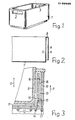
- Fig. 1 in schematischer Darstellung eine Ansicht eines mit dem Werkzeug nach der Erfindung herstellbaren Behälters.
- Fig. 2 einen teilweisen Schnitt durch den Behälter in vergrößerter Darstellung.
- Fig. 3 einen Ausschnitt aus einem Werkzeug nach der Erfindung.
- Im dargestellten Ausführungsbeispiel ist ein doppelwandiger Kasten gezeigt. Dieser Kasten und seine Herstellung bzw. das entsprechende Werkzeug werden stellvertretend für alle geometrisch möglichen Behälter erläutert, die auch mehr als zwei Teilwände haben können. Die Wandungen bzw. Teilwände müssen auch nicht eben sein bzw. parallel zueinander verlaufen, sondern es können auch gewellte Teilwände am Behälter vorhanden sein. Die Hohlräume im Werkzeug müssen dann entsprechend gestaltet sein.
- Mit 1 ist ein aus Kunststoff bestehender Behälter bezeichnet, bei welchem es sich beispielsweise um einen Flaschenkasten handelt. Der Behälter 1 ist mechanisch so stabil, daß eine größere Anzahl von gefüllten Flaschen darin transportiert werden kann. Er kann in zwei einander gegenüber liegenden Wänden mit Durchbrechungen 2 und 3 versehen sein, welche als Griffmulden dienen. Mindestens eine der Wandungen des Behälters 1 besteht aus zwei Teilwänden 4 und 5 (Fig. 2), die parallel zueinander verlaufen und einen Hohlraum 6 begrenzen. Der Hohlraum 6 kann durch der Einfachheit halber nicht dargestellte Stege auch in zwei oder mehr Hohlräume unterteilt sein.
- Die Teilwand 4 ist im dargestellten Ausführungsbeispiel kürzer als die Teilwand 5. Die Teilwand 5 geht an ihrem einen Ende in den Bo-den 7 des Behälters 1 über, während sie am anderen Ende 8 mit der Teilwand 4 verbunden ist, so daß diese Wandung des Behälters 1 im Querschnitt etwa U-förmig ausgeführt ist. Die Teilwand 4 liegt beim Behälter 1 außen.
- Zur Herstellung eines Behälters 1 wird ein Spritzgieß-Werkzeug verwendet, wie es ausschnittsweise in Fig. 3 dargestellt ist. Das Werkzeug besteht aus einem Kern 9 und einer Außenform 10, die in Richtung des Doppelpfeiles D relativ zueinander bewegbar sind. Bei geschlossenem Werkzeug verbleiben zwischen Kern 9 und Außenform 10 zusammenhängende Hohlräume 11, in welche zur Erzeugung eines Behälters 1 Spritzmaterial eingespritzt wird. Das Spritzmaterial wird dabei über Angußkanäle 12, die in der Außenform 10 angebracht sind und in die Hohlräume 11 münden, in dieselben eingespritzt.
- Der zur Erzeugung der äußeren Teilwand 4 im Werkzeug vorhandene Hohlraum 13, welcher insgesamt zu den Hohlräumen 11 gehört, hat mindestens einen eigenen Angußkanal 14. Im Gegensatz zu den Angußkanälen 12 mündet der Angußkanal 14 nicht in Richtung der durch den Pfeil P angedeuteten Entformungsrichtung, sondern quer dazu in den Hohlraum 13 ein. Das Ende 15 des Angußkanals 14 liegt dabei vorzugsweise in der inneren Seitenfläche 16 des Hohlraums 13, und zwar vorzugsweise in der Nähe des Endes dieses Hohlraums, das dem freien Ende der äußeren Teilwand 4 des herzustellenden Behälters 1 entspricht. Außerdem wird der Angußkanal 14 zweckmäßig so geführt, daß er rechtwinklig in den Hohlraum 13 einmündet.
- Für die äußere Teilwand 4 kann auch ein Angußkanal 17 verwendet werden, der in der äußeren Seitenfläche 18 des Hohlraums 13 endet. Auch der Angußkanal 17 kann rechtwinklig in den Hohlraum 13 einmünden. Er kann jedoch auch - ebenso wie der Anguß-. kanal 14 - so wie in Fig. 3 gezeigt, schräg in den Hohlraum 13 münden.
- Die spezielle Führung der Angußkanäle 14 und 17 hat den Vorteil, daß beim Entformen eines gespritzten Behälters 1 der Anguß an den Enden 15 und 19 der Angußkanäle 14 und 17 von der äußeren Teilwand 4 abreißt und im Angußkanal bleibt. Die äußere Teilwand 4 ist daher nach dem Entformen des Behälters 1 ohne Nachbearbeitung frei von Angüssen. In bevorzugter Ausführungsform wird der Angußkanal 14 eingesetzt, da dann an der äußeren Oberfläche des Behälters 1 keine Abdrücke bzw. Dellen vorhanden sind, die durch das Abscheren des Angusses entstehen könnten.
Claims (5)
Priority Applications (1)
| Application Number | Priority Date | Filing Date | Title |
|---|---|---|---|
| AT86101130T ATE34118T1 (de) | 1985-01-30 | 1986-01-29 | Werkzeug zum spritzgiessen von stapelbaren behaeltern. |
Applications Claiming Priority (2)
| Application Number | Priority Date | Filing Date | Title |
|---|---|---|---|
| DE19853503006 DE3503006A1 (de) | 1985-01-30 | 1985-01-30 | Werkzeug zum spritzgiessen von stapelbaren behaeltern |
| DE3503006 | 1985-01-30 |
Publications (3)
| Publication Number | Publication Date |
|---|---|
| EP0189906A2 true EP0189906A2 (de) | 1986-08-06 |
| EP0189906A3 EP0189906A3 (en) | 1986-10-29 |
| EP0189906B1 EP0189906B1 (de) | 1988-05-11 |
Family
ID=6261111
Family Applications (1)
| Application Number | Title | Priority Date | Filing Date |
|---|---|---|---|
| EP86101130A Expired EP0189906B1 (de) | 1985-01-30 | 1986-01-29 | Werkzeug zum Spritzgiessen von stapelbaren Behältern |
Country Status (4)
| Country | Link |
|---|---|
| EP (1) | EP0189906B1 (de) |
| AT (1) | ATE34118T1 (de) |
| DE (2) | DE3503006A1 (de) |
| DK (1) | DK161061C (de) |
Cited By (1)
| Publication number | Priority date | Publication date | Assignee | Title |
|---|---|---|---|---|
| GB2250468B (en) * | 1990-06-20 | 1994-11-16 | Takata Corp | Method of molding a modular cover for an air bag device |
Families Citing this family (1)
| Publication number | Priority date | Publication date | Assignee | Title |
|---|---|---|---|---|
| US2734497A (en) * | 1956-02-14 | chayne |
Family Cites Families (2)
| Publication number | Priority date | Publication date | Assignee | Title |
|---|---|---|---|---|
| GB1281969A (en) * | 1970-10-27 | 1972-07-19 | Flambeau Plastics Corp | Injection moulding machine for a plastics container |
| US4277435A (en) * | 1979-03-28 | 1981-07-07 | Logic Devices, Inc. | Plastic tumbler and method and apparatus for making same |
-
1985
- 1985-01-30 DE DE19853503006 patent/DE3503006A1/de not_active Withdrawn
-
1986
- 1986-01-29 EP EP86101130A patent/EP0189906B1/de not_active Expired
- 1986-01-29 AT AT86101130T patent/ATE34118T1/de not_active IP Right Cessation
- 1986-01-29 DE DE8686101130T patent/DE3660181D1/de not_active Expired
- 1986-01-30 DK DK047486A patent/DK161061C/da not_active IP Right Cessation
Cited By (1)
| Publication number | Priority date | Publication date | Assignee | Title |
|---|---|---|---|---|
| GB2250468B (en) * | 1990-06-20 | 1994-11-16 | Takata Corp | Method of molding a modular cover for an air bag device |
Also Published As
| Publication number | Publication date |
|---|---|
| ATE34118T1 (de) | 1988-05-15 |
| DK47486D0 (da) | 1986-01-30 |
| DK161061C (da) | 1991-11-11 |
| EP0189906B1 (de) | 1988-05-11 |
| EP0189906A3 (en) | 1986-10-29 |
| DK47486A (da) | 1986-07-31 |
| DK161061B (da) | 1991-05-27 |
| DE3660181D1 (en) | 1988-06-16 |
| DE3503006A1 (de) | 1986-08-07 |
Similar Documents
| Publication | Publication Date | Title |
|---|---|---|
| DE2918926C2 (de) | Spritzgießform zum Herstellen von aus mindestens zwei verschiedenen Kunststoffmassen bestehenden und mindestens zwei unterschiedliche Bereiche aufweisenden Spritzgußteilen | |
| EP2098352B1 (de) | Spritzgiesswerkzeug | |
| EP0490165B1 (de) | Transportbehälter, insbesondere Flaschenkasten aus Kunststoff | |
| DE3113071C2 (de) | ||
| EP0189906B1 (de) | Werkzeug zum Spritzgiessen von stapelbaren Behältern | |
| EP0061072A2 (de) | Spritzgiessform | |
| DE2348608B2 (de) | Vorrichtung zum Herstellen von Schaum- oder Homogenstoffen aus fließfähigen Reaktionskomponenten | |
| EP0595203B1 (de) | Spritzgussvorrichtung | |
| DE2848374A1 (de) | Flaschenverpackung | |
| DE3900894A1 (de) | Verfahren zur herstellung von flaschenkaesten mit waagrechten griffholmen sowie entsprechende flaschenkaesten | |
| DE102004009406A1 (de) | Werkzeug | |
| EP0687630B1 (de) | Im Spritzgiessverfahren hergestelltes Kunstoffteil | |
| EP0753390B1 (de) | Spritzgiesswerkzeug zur Herstellung eines aus Kunststoff bestehenden Kastens | |
| DE4203696C2 (de) | Vorrichtung zum Spritzgießen eines Formteils aus Kunststoff | |
| DE2753337C2 (de) | Spritzgießform zum Herstellen eines dosenförmigen Spitzers mit einem umspritzten Messer | |
| DE2325949C3 (de) | Gewindekern für eine SpritzgieBvorr ich tu ng zum Herstellen eines mit einem Innen-Gewinde versehenen Formteils | |
| DE19932515A1 (de) | Kasten aus Kunststoff und Vorrichtung zur Herstellung eines Kastens | |
| DE2849145A1 (de) | Spritzgiessform fuer transportkaesten, insbesondere flaschenkaesten | |
| DE1479748C2 (de) | Maschine zum Herstellen von Formteilen aus expandierbaren Kunststoffen | |
| EP0465492B1 (de) | Teilbarer flaschenkasten | |
| DE1529988C (de) | Spritzguß Vorrichtung | |
| DE3111216C2 (de) | Spritzgießform für kastenförmige Spritzlinge, insbesondere Flaschenkästen | |
| DE4330998A1 (de) | Transportkasten aus Kunststoff | |
| EP0484763A2 (de) | Verfahren und Vorrichtung zur Herstellung von Transportkästen, insbesondere Flaschenkästen | |
| DE4421685A1 (de) | Im Spritzgießverfahren hergestelltes Kunststoffteil |
Legal Events
| Date | Code | Title | Description |
|---|---|---|---|
| PUAI | Public reference made under article 153(3) epc to a published international application that has entered the european phase |
Free format text: ORIGINAL CODE: 0009012 |
|
| AK | Designated contracting states |
Kind code of ref document: A2 Designated state(s): AT BE CH DE FR GB IT LI LU NL SE |
|
| PUAL | Search report despatched |
Free format text: ORIGINAL CODE: 0009013 |
|
| ITCL | It: translation for ep claims filed |
Representative=s name: MODIANO & ASSOCIATI S.R.L. |
|
| AK | Designated contracting states |
Kind code of ref document: A3 Designated state(s): AT BE CH DE FR GB IT LI LU NL SE |
|
| EL | Fr: translation of claims filed | ||
| TCNL | Nl: translation of patent claims filed | ||
| 17P | Request for examination filed |
Effective date: 19861112 |
|
| 17Q | First examination report despatched |
Effective date: 19870729 |
|
| GRAA | (expected) grant |
Free format text: ORIGINAL CODE: 0009210 |
|
| AK | Designated contracting states |
Kind code of ref document: B1 Designated state(s): AT BE CH DE FR GB IT LI LU NL SE |
|
| REF | Corresponds to: |
Ref document number: 34118 Country of ref document: AT Date of ref document: 19880515 Kind code of ref document: T |
|
| REF | Corresponds to: |
Ref document number: 3660181 Country of ref document: DE Date of ref document: 19880616 |
|
| ET | Fr: translation filed | ||
| ITF | It: translation for a ep patent filed | ||
| GBT | Gb: translation of ep patent filed (gb section 77(6)(a)/1977) | ||
| PG25 | Lapsed in a contracting state [announced via postgrant information from national office to epo] |
Ref country code: LU Free format text: LAPSE BECAUSE OF NON-PAYMENT OF DUE FEES Effective date: 19890131 |
|
| PLBE | No opposition filed within time limit |
Free format text: ORIGINAL CODE: 0009261 |
|
| 26N | No opposition filed | ||
| ITTA | It: last paid annual fee | ||
| PGFP | Annual fee paid to national office [announced via postgrant information from national office to epo] |
Ref country code: FR Payment date: 19911125 Year of fee payment: 7 |
|
| PGFP | Annual fee paid to national office [announced via postgrant information from national office to epo] |
Ref country code: CH Payment date: 19911128 Year of fee payment: 7 |
|
| PGFP | Annual fee paid to national office [announced via postgrant information from national office to epo] |
Ref country code: BE Payment date: 19911129 Year of fee payment: 7 |
|
| PGFP | Annual fee paid to national office [announced via postgrant information from national office to epo] |
Ref country code: GB Payment date: 19911218 Year of fee payment: 7 |
|
| PGFP | Annual fee paid to national office [announced via postgrant information from national office to epo] |
Ref country code: SE Payment date: 19920117 Year of fee payment: 7 |
|
| PGFP | Annual fee paid to national office [announced via postgrant information from national office to epo] |
Ref country code: AT Payment date: 19920128 Year of fee payment: 7 |
|
| PGFP | Annual fee paid to national office [announced via postgrant information from national office to epo] |
Ref country code: NL Payment date: 19920131 Year of fee payment: 7 |
|
| PGFP | Annual fee paid to national office [announced via postgrant information from national office to epo] |
Ref country code: DE Payment date: 19920525 Year of fee payment: 7 |
|
| PG25 | Lapsed in a contracting state [announced via postgrant information from national office to epo] |
Ref country code: GB Effective date: 19930129 Ref country code: AT Effective date: 19930129 |
|
| PG25 | Lapsed in a contracting state [announced via postgrant information from national office to epo] |
Ref country code: SE Effective date: 19930130 |
|
| PG25 | Lapsed in a contracting state [announced via postgrant information from national office to epo] |
Ref country code: CH Effective date: 19930131 Ref country code: BE Effective date: 19930131 Ref country code: LI Effective date: 19930131 |
|
| BERE | Be: lapsed |
Owner name: FRIEDRICH THEYSOHN G.M.B.H. Effective date: 19930131 |
|
| PG25 | Lapsed in a contracting state [announced via postgrant information from national office to epo] |
Ref country code: NL Effective date: 19930801 |
|
| NLV4 | Nl: lapsed or anulled due to non-payment of the annual fee | ||
| GBPC | Gb: european patent ceased through non-payment of renewal fee |
Effective date: 19930129 |
|
| PG25 | Lapsed in a contracting state [announced via postgrant information from national office to epo] |
Ref country code: FR Effective date: 19930930 |
|
| REG | Reference to a national code |
Ref country code: CH Ref legal event code: PL |
|
| PG25 | Lapsed in a contracting state [announced via postgrant information from national office to epo] |
Ref country code: DE Effective date: 19931001 |
|
| REG | Reference to a national code |
Ref country code: FR Ref legal event code: ST |
|
| EUG | Se: european patent has lapsed |
Ref document number: 86101130.2 Effective date: 19930810 |
|
| PG25 | Lapsed in a contracting state [announced via postgrant information from national office to epo] |
Ref country code: IT Free format text: LAPSE BECAUSE OF NON-PAYMENT OF DUE FEES;WARNING: LAPSES OF ITALIAN PATENTS WITH EFFECTIVE DATE BEFORE 2007 MAY HAVE OCCURRED AT ANY TIME BEFORE 2007. THE CORRECT EFFECTIVE DATE MAY BE DIFFERENT FROM THE ONE RECORDED. Effective date: 20050129 |