EP0189909A2 - Procédé et dispositif pour la fabrication des flancs de boîtes pliables - Google Patents
Procédé et dispositif pour la fabrication des flancs de boîtes pliables Download PDFInfo
- Publication number
- EP0189909A2 EP0189909A2 EP86101145A EP86101145A EP0189909A2 EP 0189909 A2 EP0189909 A2 EP 0189909A2 EP 86101145 A EP86101145 A EP 86101145A EP 86101145 A EP86101145 A EP 86101145A EP 0189909 A2 EP0189909 A2 EP 0189909A2
- Authority
- EP
- European Patent Office
- Prior art keywords
- grooves
- plotter
- folding box
- holder
- folding
- Prior art date
- Legal status (The legal status is an assumption and is not a legal conclusion. Google has not performed a legal analysis and makes no representation as to the accuracy of the status listed.)
- Withdrawn
Links
- 238000000034 method Methods 0.000 title claims description 18
- 238000005520 cutting process Methods 0.000 claims abstract description 20
- 238000004519 manufacturing process Methods 0.000 claims description 11
- 238000003825 pressing Methods 0.000 claims description 5
- 238000011960 computer-aided design Methods 0.000 claims description 4
- 238000004080 punching Methods 0.000 description 5
- 206010040954 Skin wrinkling Diseases 0.000 description 2
- 238000010586 diagram Methods 0.000 description 2
- 238000003801 milling Methods 0.000 description 2
- 239000011324 bead Substances 0.000 description 1
- 230000015572 biosynthetic process Effects 0.000 description 1
- 238000010276 construction Methods 0.000 description 1
- 239000000463 material Substances 0.000 description 1
- 239000011148 porous material Substances 0.000 description 1
Images
Classifications
-
- B—PERFORMING OPERATIONS; TRANSPORTING
- B31—MAKING ARTICLES OF PAPER, CARDBOARD OR MATERIAL WORKED IN A MANNER ANALOGOUS TO PAPER; WORKING PAPER, CARDBOARD OR MATERIAL WORKED IN A MANNER ANALOGOUS TO PAPER
- B31F—MECHANICAL WORKING OR DEFORMATION OF PAPER, CARDBOARD OR MATERIAL WORKED IN A MANNER ANALOGOUS TO PAPER
- B31F1/00—Mechanical deformation without removing material, e.g. in combination with laminating
- B31F1/08—Creasing
- B31F1/10—Creasing by rotary tools
-
- B—PERFORMING OPERATIONS; TRANSPORTING
- B31—MAKING ARTICLES OF PAPER, CARDBOARD OR MATERIAL WORKED IN A MANNER ANALOGOUS TO PAPER; WORKING PAPER, CARDBOARD OR MATERIAL WORKED IN A MANNER ANALOGOUS TO PAPER
- B31F—MECHANICAL WORKING OR DEFORMATION OF PAPER, CARDBOARD OR MATERIAL WORKED IN A MANNER ANALOGOUS TO PAPER
- B31F1/00—Mechanical deformation without removing material, e.g. in combination with laminating
- B31F1/08—Creasing
-
- B—PERFORMING OPERATIONS; TRANSPORTING
- B31—MAKING ARTICLES OF PAPER, CARDBOARD OR MATERIAL WORKED IN A MANNER ANALOGOUS TO PAPER; WORKING PAPER, CARDBOARD OR MATERIAL WORKED IN A MANNER ANALOGOUS TO PAPER
- B31B—MAKING CONTAINERS OF PAPER, CARDBOARD OR MATERIAL WORKED IN A MANNER ANALOGOUS TO PAPER
- B31B50/00—Making rigid or semi-rigid containers, e.g. boxes or cartons
- B31B50/25—Surface scoring
- B31B50/252—Surface scoring using presses or dies
-
- B—PERFORMING OPERATIONS; TRANSPORTING
- B31—MAKING ARTICLES OF PAPER, CARDBOARD OR MATERIAL WORKED IN A MANNER ANALOGOUS TO PAPER; WORKING PAPER, CARDBOARD OR MATERIAL WORKED IN A MANNER ANALOGOUS TO PAPER
- B31B—MAKING CONTAINERS OF PAPER, CARDBOARD OR MATERIAL WORKED IN A MANNER ANALOGOUS TO PAPER
- B31B50/00—Making rigid or semi-rigid containers, e.g. boxes or cartons
- B31B50/25—Surface scoring
- B31B50/256—Surface scoring using tools mounted on a drum
Definitions
- the invention relates to a method for producing a folding box blank, in which it is cut out of a cardboard sheet and at least one groove is pressed into it to form each folding line, and a device for carrying out this method.
- the usual known method of this type is that for each folding line a deep groove is pressed in on the side of the cardboard sheet, which forms the outside of the folding box after folding.
- This groove must be so deep that it emerges as a bulge on the side of the folding box blank that forms the inside after the folding box has been folded. Thereby folding becomes possible without tearing the material.
- the folding box blank is punched out of a cardboard sheet by means of a punching tool which at the same time forms the grooves.
- the base on which the cardboard sheet is placed must have channels for receiving the grooves embossed during punching. Both the punching tool itself and the base for punching out a folding box blank are relatively complicated tools to manufacture. For cost reasons, this known method is therefore unsuitable for the production of patterns for folding boxes.
- a cardboard sheet is placed with the side on the form that later forms the inside of the folded folding box.
- the cardboard sheet is then pressed onto the form plate by means of a cylindrically curved surface, so that the folding box blank is cut out and the grooves are pressed in at the same time.
- the known folding box blanks for folding box patterns are therefore produced in such a way that the grooves necessary for folding are made by hand by the pattern maker in a blank cut from a cardboard sheet.
- the folding box blank not yet provided with grooves is placed with the side that later forms the inside of the folding box on a template with a channel groove in such a way that the channel groove lies under the desired groove.
- the pattern maker then embosses the groove into the outside of the box cut with a folding leg. Since a folding box blank has many grooves running in different directions, this process is very cumbersome and also expensive because of the high labor costs.
- the invention is based on the object of specifying a method and creating a device by means of which folding box blanks can be produced in small numbers, that is to say for folding box patterns, with little effort.
- the method according to the invention for producing a folding box blank consists in that a plotter with a computer system for computer-aided design and manufacture is used for cutting and pressing in the grooves and its computer system is preprogrammed such that its holder is longitudinal after a first and a second program Paths is guided, which correspond to the course of the grooves or the outline of the folding box cut, that the cardboard sheet is detachably held on the uninterrupted surface of the table of the plotter, that a printing tool is inserted into the holder of the plotter and the plotter is switched on, so that when Carrying out the first program of the holder moves the printing tool along the preprogrammed paths and thereby presses in the grooves, that the printing tool in the holder is then exchanged for a cutting tool and, when carrying out the second program, the holder moves the cutting tool along the outline and thereby the groove provided folding box cut out.
- “Plotter” is understood here to mean a machine which, like an EDP system-controlled drawing machine, has a table and a holder which can be moved over the table according to XY coordinates.
- the cardboard sheet is placed on a smooth surface, namely the surface of the plotter table, and then the grooves are pressed in by a printing tool guided over the surface of the cardboard sheet, the folding box blank produced in this way along the folding lines defined by these grooves can be folded properly.
- Particularly advantageous conditions result when the cardboard sheet is placed with one side on the plotter's table and at least two mutually parallel grooves are pressed into the other side of the cardboard sheet for each folding line of the folding box blank,
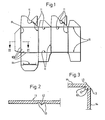
- the folding box blank of cardboard shown in FIG. 1 has, on the side which forms the inside of the folding box after folding, groove pairs 11 formed from mutually parallel grooves 10. As can be seen from FIG. 2, the groove depth is less than half and the distance between the groove centers from one another is approximately twice the cardboard thickness. Through these grooves it is achieved that the inner cardboard surface 12 of a folding box made from the folding box blank bulges slightly between the two grooves 10 of each pair of grooves 11. This has the consequence that when the carton is folded around the fold lines defined by the pairs of grooves 11, the inner carton surface 12 forms a bulge, as is shown enlarged in FIG. At the same time, the locations on the outside of the carton opposite the bottoms of the two grooves 10 form the crease lines 13 shown in FIG. 3, which delimit the flat areas 14 on the outside of the folding box.
- the folding box blank according to FIG. 1 described above is a preferred embodiment. Instead of two grooves 10 forming a groove pair 11, only one or more than two, e.g. three grooves may be provided. The grooves can also be pressed into the side that later forms the outside of the folding box.
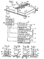
- a conventional EDP system-controlled drawing machine can be used for the machine for producing the folding box blanks shown in FIG. It is therefore briefly referred to below as a plotter and accordingly has an uninterrupted flat table surface of a table 20 which has parallel rails 21 and 22 on two opposite longitudinal sides, on which a carriage 23 extending over the table 20 along one in the Drawing with X designated coordinate is movable.
- a carriage 24 is displaceable through transverse rails 25 and 26 perpendicular to the X axis, that is to say along the axis designated Y in the drawing.
- the carriage 24 carries a holder S8, in which, as with the plotter. a drawing pen or the like, a printing tool or a cutting tool can be used.
- This holder 28 can be moved up and down along the axis designated Z in the drawing, perpendicular to the surface of the table 20, and is rotatably mounted in the slide 24 about the Z axis.
- the table top can be made of a porous material, so that cardboard sheets placed on the table can be detachably held thereon by applying a vacuum to the underside of the table top.
- the four arrows 30 shown in Fig. 4 are intended to indicate such a means for holding the cardboard sheet on the table top, which means both by said vacuum or by another, e.g. mechanical means can be realized.
- the plotter shown in simplified form in FIG. 4 has drives, not shown in the drawing, for the translational movement of the carriage 23 along the X axis, for the translational movement of the carriage 24 along the Y axis, for the translational movement of the holder 28 along the Z axis and for the rotation of the holder 28 about the Z axis.
- the schematic diagram according to FIG. 5 shows an EDP system 35 for computer-aided design and manufacture with a screen 37 and the drive controls 31, 32 and 33 for the translational movement of the carriage along the X axis, the carriage along the Y axis and of the holder along the Z-axis and a controller 34 for rotating the holder 28 about the Z-axis.
- the desired folding lines and cutting lines can be arranged exactly with respect to one another, so that the preprogramming for the EDP system for performing the movements of the holder for pressing in the grooves and for cutting out the folding box blank results.
- the EDP system must therefore be preprogrammed for two different programs, namely for a program for producing the grooves 10 and for a second program for cutting out the folding box blank, which run in succession with the appropriate tools, and also an automatic changing device, not shown in the drawing can be provided, which automatically exchanges the tool for pressing in the grooves against a cutting tool after the end of the first program and then allows the second program to run.
- FIG. 6 shows a simplified view of a printing tool 40 for producing two mutually parallel grooves 10.
- This tool has a shaft 41 which can be inserted into the chuck of the holder 28 and which is provided with a slot 42 around the shaft 41 in a rotationally fixed manner with the holder 28 to connect.
- a pressure roller 43 is connected to the shaft 41 so as to be rotatable about an axis 24 perpendicular to the shaft and thus to the Z axis of the holder 28 and has two beads 45 which are provided for simultaneously pressing grooves 10 parallel to one another.
- a ball 47 which is rotatably mounted on all sides at the lower end of the shaft 41 is provided.
- a construction corresponding to the known ballpoint pens can be used for this printing tool.
- This embodiment has been particularly well suited. While the holder 28 must be rotated about the Z-axis in the embodiment according to FIG. 6 for pairs of grooves which form angles with one another, this is not necessary in the embodiment according to FIG. 6A.
- the control of this printing tool 40" must correspond to the control of the Pressure tool 40 according to Figure 6 take place, ie here, too, the tool for indenting grooves that form angles with one another must be rotated about the Z axis.
- a cutting tool 50 is shown only schematically in FIG. 7, which has a shaft 51 which, like the shaft 41 of the printing tools, has a slot 52 in order to connect it to the holder 28 in a rotationally fixed manner.
- a circular knife 53 is rotatably mounted about the axis 54 perpendicular to the Z axis.
- a fixed knife can also be provided, which is guided in a tangential cut over the cardboard sheet.
- the computer system 35 is first preprogrammed with the aid of the screen for the two programs for producing the grooves 10 and for cutting out the folding box blank. Then a cardboard sheet 46 is placed with the side on the table surface of the plotter table 20, which later forms the outside of the folded folding box. After a printing tool 40, 40 'or 40 "has been inserted into the holder 28, the first programmed program of the computer system is run so that the grooves 10 are pressed in pairs for each folding line without them being on the outside of the Then use a cutting tool, such as a milling cutter, a tangential knife or a circular knife 53 (Fig.
Landscapes
- Engineering & Computer Science (AREA)
- Mechanical Engineering (AREA)
- Making Paper Articles (AREA)
Applications Claiming Priority (2)
| Application Number | Priority Date | Filing Date | Title |
|---|---|---|---|
| DE3503001 | 1985-01-30 | ||
| DE3503001 | 1985-01-30 |
Publications (1)
| Publication Number | Publication Date |
|---|---|
| EP0189909A2 true EP0189909A2 (fr) | 1986-08-06 |
Family
ID=6261107
Family Applications (1)
| Application Number | Title | Priority Date | Filing Date |
|---|---|---|---|
| EP86101145A Withdrawn EP0189909A2 (fr) | 1985-01-30 | 1986-01-29 | Procédé et dispositif pour la fabrication des flancs de boîtes pliables |
Country Status (1)
| Country | Link |
|---|---|
| EP (1) | EP0189909A2 (fr) |
Cited By (18)
| Publication number | Priority date | Publication date | Assignee | Title |
|---|---|---|---|---|
| US4816015A (en) * | 1985-08-01 | 1989-03-28 | Karl Holder | Machine for producing pattern cardboard articles |
| US4994008A (en) * | 1989-06-01 | 1991-02-19 | Rsr Machine Builders, Inc. | Machine for producing container blanks from flat stock |
| US5001325A (en) * | 1988-09-07 | 1991-03-19 | Lpf Verpakkingen B.V. | Method of providing score lines in packaging material |
| US5010231A (en) * | 1989-05-19 | 1991-04-23 | Lpf Verpakkingen B.V. | Method of forming lines of weakness in or grooving a plastic material, especially a packaging material |
| WO1997037837A1 (fr) * | 1996-04-10 | 1997-10-16 | Comag Printing & Converting Systems Ag | Procede de production d'objets par pliage de materiau plat et objet produit a l'aide dudit procede |
| AT406353B (de) * | 1998-06-30 | 2000-04-25 | Wolf Systembau Gmbh & Co Kg | Markierungseinrichtung zum verbinden von holzbalken mittels nagelplatten |
| WO2002070241A1 (fr) * | 2001-03-06 | 2002-09-12 | Hilfling Royalty A/S | Procede et outil permettant d'estamper un bord de pliage dans un materiau d'emballage |
| DE19851091B4 (de) * | 1997-11-07 | 2004-12-09 | Griffin Automation, Inc. | Verfahren zum Formen geschlitzter und gefalzter Schachtel-Zuschnitte |
| US7311648B2 (en) * | 2001-03-06 | 2007-12-25 | Jes Hilfing Petersen | Method for stamping a bending edge in a package material |
| DE19944099B4 (de) * | 1998-09-17 | 2008-04-30 | Caretec Ges.M.B.H. | Vorrichtung zur Herstellung von taktil erfassbaren Erhabenheiten |
| ITBO20100519A1 (it) * | 2010-08-11 | 2012-02-12 | Swisslog Italia Spa | Dispositivo e procedimento per singolarizzare prodotti |
| JP2014176958A (ja) * | 2013-03-13 | 2014-09-25 | Xerox Corp | 媒体を切断および折り目付けする装置、システム、および方法 |
| CN104890292A (zh) * | 2015-05-27 | 2015-09-09 | 蚌埠市振华包装机械有限责任公司 | 一种便于操作的纸箱压痕装置 |
| CN104890291A (zh) * | 2015-05-27 | 2015-09-09 | 蚌埠市振华包装机械有限责任公司 | 一种全自动可调纸箱压痕装置 |
| CN104924669A (zh) * | 2015-05-27 | 2015-09-23 | 蚌埠市振华包装机械有限责任公司 | 一种纸箱全自动压痕装置 |
| CN104960244A (zh) * | 2015-05-27 | 2015-10-07 | 蚌埠市振华包装机械有限责任公司 | 一种压线精准的纸箱压痕机 |
| CN117901482A (zh) * | 2024-02-29 | 2024-04-19 | 武汉虹之彩包装印刷有限公司 | 一种硬质卡纸的开槽装置、方法及制盒系统 |
| WO2024151983A1 (fr) * | 2023-01-13 | 2024-07-18 | Electronics For Imaging, Inc | Imprimante à plat à fonctions de rainage et découpe intégrées |
-
1986
- 1986-01-29 EP EP86101145A patent/EP0189909A2/fr not_active Withdrawn
Cited By (23)
| Publication number | Priority date | Publication date | Assignee | Title |
|---|---|---|---|---|
| US4816015A (en) * | 1985-08-01 | 1989-03-28 | Karl Holder | Machine for producing pattern cardboard articles |
| US5001325A (en) * | 1988-09-07 | 1991-03-19 | Lpf Verpakkingen B.V. | Method of providing score lines in packaging material |
| US5010231A (en) * | 1989-05-19 | 1991-04-23 | Lpf Verpakkingen B.V. | Method of forming lines of weakness in or grooving a plastic material, especially a packaging material |
| US4994008A (en) * | 1989-06-01 | 1991-02-19 | Rsr Machine Builders, Inc. | Machine for producing container blanks from flat stock |
| WO1997037837A1 (fr) * | 1996-04-10 | 1997-10-16 | Comag Printing & Converting Systems Ag | Procede de production d'objets par pliage de materiau plat et objet produit a l'aide dudit procede |
| DE19851091B4 (de) * | 1997-11-07 | 2004-12-09 | Griffin Automation, Inc. | Verfahren zum Formen geschlitzter und gefalzter Schachtel-Zuschnitte |
| AT406353B (de) * | 1998-06-30 | 2000-04-25 | Wolf Systembau Gmbh & Co Kg | Markierungseinrichtung zum verbinden von holzbalken mittels nagelplatten |
| DE19944099B4 (de) * | 1998-09-17 | 2008-04-30 | Caretec Ges.M.B.H. | Vorrichtung zur Herstellung von taktil erfassbaren Erhabenheiten |
| WO2002070241A1 (fr) * | 2001-03-06 | 2002-09-12 | Hilfling Royalty A/S | Procede et outil permettant d'estamper un bord de pliage dans un materiau d'emballage |
| US7311648B2 (en) * | 2001-03-06 | 2007-12-25 | Jes Hilfing Petersen | Method for stamping a bending edge in a package material |
| ITBO20100519A1 (it) * | 2010-08-11 | 2012-02-12 | Swisslog Italia Spa | Dispositivo e procedimento per singolarizzare prodotti |
| WO2012020354A1 (fr) * | 2010-08-11 | 2012-02-16 | Swisslog Italia S.P.A. | Dispositif et procédé permettant de séparer des produits |
| CN103108809A (zh) * | 2010-08-11 | 2013-05-15 | 思维斯洛格意大利股份公司 | 用于拣选产品的设备和方法 |
| CN103108809B (zh) * | 2010-08-11 | 2014-08-27 | 思维斯洛格意大利股份公司 | 用于拣选产品的设备和方法 |
| US9308661B2 (en) | 2010-08-11 | 2016-04-12 | Swisslog Italia S.P.A. | Device and method for singling out products |
| JP2014176958A (ja) * | 2013-03-13 | 2014-09-25 | Xerox Corp | 媒体を切断および折り目付けする装置、システム、および方法 |
| CN104890292A (zh) * | 2015-05-27 | 2015-09-09 | 蚌埠市振华包装机械有限责任公司 | 一种便于操作的纸箱压痕装置 |
| CN104890291A (zh) * | 2015-05-27 | 2015-09-09 | 蚌埠市振华包装机械有限责任公司 | 一种全自动可调纸箱压痕装置 |
| CN104924669A (zh) * | 2015-05-27 | 2015-09-23 | 蚌埠市振华包装机械有限责任公司 | 一种纸箱全自动压痕装置 |
| CN104960244A (zh) * | 2015-05-27 | 2015-10-07 | 蚌埠市振华包装机械有限责任公司 | 一种压线精准的纸箱压痕机 |
| WO2024151983A1 (fr) * | 2023-01-13 | 2024-07-18 | Electronics For Imaging, Inc | Imprimante à plat à fonctions de rainage et découpe intégrées |
| US12350928B2 (en) | 2023-01-13 | 2025-07-08 | Electronics For Imaging, Inc. | Flatbed printer with integrated creasing and cutting |
| CN117901482A (zh) * | 2024-02-29 | 2024-04-19 | 武汉虹之彩包装印刷有限公司 | 一种硬质卡纸的开槽装置、方法及制盒系统 |
Similar Documents
| Publication | Publication Date | Title |
|---|---|---|
| DE19851091B4 (de) | Verfahren zum Formen geschlitzter und gefalzter Schachtel-Zuschnitte | |
| DE3871820T2 (de) | Flexodruckplatte. | |
| EP0665081B1 (fr) | Procédé d'usinage d'une matrice de découpage, fabriquée par photogravure d'une base-podeur | |
| DE2710855C2 (de) | Vorrichtung zum Ausstanzen von Werkstückrohlingen | |
| DE3527537C2 (de) | Maschine zum Herstellen von Musterkartonagen | |
| DE19527620A1 (de) | Vorrichtung und Verfahren zur Herstellung eines Airbag-Hohlkörpers | |
| DE2149850A1 (de) | Verfahren und Vorrichtung zur Herstellung von Faltrillen in Karton | |
| DE3728888C2 (fr) | ||
| AT393845B (de) | Bett zum abstuetzen von in gespanntem zustand aufliegendem flachmaterial | |
| DE69406514T2 (de) | Verfahren und Vorrichtung zur Herstellung eines geschnittenen kunstoffimprägnierten Bandes | |
| DE3633448A1 (de) | Schneidvorrichtung | |
| DE102015222178A1 (de) | Perforationssystem und Verfahren | |
| DE2637078C3 (de) | Verfahren und Vorrichtung zur Bearbeitung des Fußes von gestanzten Strick- oder Wirkmaschinennadeln bzw. von Platinen, Nadelschiebern, Stößern o.dgl. | |
| DE69307256T2 (de) | Positionieranschlagvorrichtung für Platten | |
| DE2833618A1 (de) | Rotationspraegemaschine mit ineinandergreifenden justierbaren praegeformen | |
| EP0366053B1 (fr) | Dispositif de fabrication de gabarit de profilé | |
| EP0362833A2 (fr) | Machine de travail du bois, de préférence une moulurière | |
| DE3420763A1 (de) | Verfahren und vorrichtung zum wahlweisen besticken und/oder gravieren und/oder bemalen und/oder perforieren von materialbahnen bzw. zuschnitten aus fuer nadel und bohrer durchlaessigen oder undurchlaessigen materialien | |
| DE19617688A1 (de) | Verfahren und Ausbrechwerkzeug zum Ausbrechen von Stanzabfällen bei der Herstellung von Zuschnitten aus einem Bogen | |
| EP0116811B1 (fr) | Dispositif pour la réalisation de patrons ou de gabarits en carton ou papier ondulé | |
| EP0714720B1 (fr) | Machine pour estamper et couper | |
| DE657505C (de) | Verfahren und Maschine zum Herstellen von Schachtelzuschnitten aus Pappe, Karton o. dgl. | |
| EP1672084B1 (fr) | Procédé et dispositif pour traiter automatiquement des pièces non-métalliques flexibles | |
| DE3619765A1 (de) | Verfahren zur herstellung einer schneidwerkzeugeinrichtung sowie nach diesem verfahren hergestellte werkzeugeinrichtung | |
| DE19603076A1 (de) | Verfahren und Vorrichtung zur Herstellung von gefalteten Flächenbahnen |
Legal Events
| Date | Code | Title | Description |
|---|---|---|---|
| PUAI | Public reference made under article 153(3) epc to a published international application that has entered the european phase |
Free format text: ORIGINAL CODE: 0009012 |
|
| AK | Designated contracting states |
Kind code of ref document: A2 Designated state(s): AT BE CH DE FR GB IT LI LU NL SE |
|
| STAA | Information on the status of an ep patent application or granted ep patent |
Free format text: STATUS: THE APPLICATION HAS BEEN WITHDRAWN |
|
| 18W | Application withdrawn |
Withdrawal date: 19880107 |
|
| RIN1 | Information on inventor provided before grant (corrected) |
Inventor name: BUTENUTH, DIETER, DIPL.-ING. Inventor name: BUTENUTH, MANFRED |