EP0190357B1 - Steuerungsvorrichtung der multidirektionellen profilierung - Google Patents
Steuerungsvorrichtung der multidirektionellen profilierung Download PDFInfo
- Publication number
- EP0190357B1 EP0190357B1 EP85903703A EP85903703A EP0190357B1 EP 0190357 B1 EP0190357 B1 EP 0190357B1 EP 85903703 A EP85903703 A EP 85903703A EP 85903703 A EP85903703 A EP 85903703A EP 0190357 B1 EP0190357 B1 EP 0190357B1
- Authority
- EP
- European Patent Office
- Prior art keywords
- axis
- tracer
- angle
- profiling
- correction angle
- Prior art date
- Legal status (The legal status is an assumption and is not a legal conclusion. Google has not performed a legal analysis and makes no representation as to the accuracy of the status listed.)
- Expired - Lifetime
Links
- 239000000700 radioactive tracer Substances 0.000 claims abstract description 48
- 241001422033 Thestylus Species 0.000 claims description 3
- 238000006073 displacement reaction Methods 0.000 abstract 1
- 239000002131 composite material Substances 0.000 description 6
- 238000010586 diagram Methods 0.000 description 5
- 230000007547 defect Effects 0.000 description 1
- 238000000034 method Methods 0.000 description 1
- 238000012544 monitoring process Methods 0.000 description 1
Images

Classifications
-
- B—PERFORMING OPERATIONS; TRANSPORTING
- B23—MACHINE TOOLS; METAL-WORKING NOT OTHERWISE PROVIDED FOR
- B23Q—DETAILS, COMPONENTS, OR ACCESSORIES FOR MACHINE TOOLS, e.g. ARRANGEMENTS FOR COPYING OR CONTROLLING; MACHINE TOOLS IN GENERAL CHARACTERISED BY THE CONSTRUCTION OF PARTICULAR DETAILS OR COMPONENTS; COMBINATIONS OR ASSOCIATIONS OF METAL-WORKING MACHINES, NOT DIRECTED TO A PARTICULAR RESULT
- B23Q35/00—Control systems or devices for copying directly from a pattern or a master model; Devices for use in copying manually
- B23Q35/04—Control systems or devices for copying directly from a pattern or a master model; Devices for use in copying manually using a feeler or the like travelling along the outline of the pattern, model or drawing; Feelers, patterns, or models therefor
- B23Q35/08—Means for transforming movement of the feeler or the like into feed movement of tool or work
- B23Q35/12—Means for transforming movement of the feeler or the like into feed movement of tool or work involving electrical means
- B23Q35/121—Means for transforming movement of the feeler or the like into feed movement of tool or work involving electrical means using mechanical sensing
- B23Q35/123—Means for transforming movement of the feeler or the like into feed movement of tool or work involving electrical means using mechanical sensing the feeler varying the impedance in a circuit
Definitions
- the present invention relates to improvements in an arbitrary-direction tracer control unit which permits arbitrary setting of the tracer feed direction.
- An example of such a unit is disclosed in EP-A-0042304.
- tracer feed rates Va and Vz in the A-axis and the Z-axis are derived from a deflection signal obtained from a tracer head.
- Previously proposed arbitrary-direction tracer control equipment is of the type that prestores the angle ⁇ between the X-axis and the A-axis in a memory, and performs the above-mentioned operations on the basis of the stored contents of the memory to obtain the feed rates in the X- and Y-axis directions.
- the tracer feed direction cannot be changed unless the stored contents of the memory are changed. Accordingly, with the previously proposed equipment, it is difficult for an operator to change the tracer feed direction while monitoring the cutting conditions.
- the present invention obviates such a defect as mentioned above, and has for its object to permit an easy change of the tracer feed direction even during tracing.
- an arbitrary-direction tracer control unit comprising a tracer head for outputting a deflection signal corresponding to the deflection of a stylus in contact with the surface of a model, characterised by: a memory for storing a commanded angle between a coordinate axis and the tracer feed axis; a correction angle setting means for setting a correction angle with respect to the tracer feed axis; an adder means for adding together the commanded angle stored in the memory and the correction angle set by the correction angle setting means; and a tracing operation means for obtaining, on the basis of the added output of the adder means and the deflection signal from the tracer head, feed rates in the axis directions in which the model and the stylus are moved relative to each other which will drive the tracer head relative to the model in a direction corresponding to the added output from the adder means.
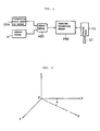
- Fig. 1 is a block diagram illustrating the arrangement of the present invention.
- a memory means M has stored therein a commanded angle indicating the direction of the tracer feed axis, that is, an angle between the X-axis and the tracer feed axis.
- a correction angle setting means COM is to set a correction angle with respect to the tracer feed axis direction.
- An adder means ADD adds together the angle stored in the memory means M and the correction angle set by the correction angle setting means COM and then provides the added output to a tracing operation means PRO.
- the tracing operation means PRO Based on the results of the addition by the adder means ADD and a deflection signal corresponding to the deflection of a stylus ST provided from a tracer head TH, the tracing operation means PRO obtains the feed rate in each axis direction at which the model and the tracer head are moved relative to each other, thereby to provide the direction corresponding to the results of the addition by the adder means ADD.
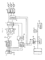
- Fig. 2 illustrates in block form an embodiment of the present invention.
- Reference numeral 1 indicates a tracer head, 2 a stylus, 3 a composite deflection signal generator, 4 an adder, 5 and 6 velocity calculation circuits for obtaining normal-direction velocity V N and tangential-direction velocity V T , 7 a distribution circuit, 8 and 9 coordinate converters, 10 an indexing circuit, 11 to 13 X-, Y- and Z-axis amplifiers, 14 to 16 X-, Y- and Z-axis motors, 17 a microprocessor, 18 an output port, 19 a memory, 20 a keyboard, and 21 a correction angle setting dial for setting a correction angle with respect to the tracer feed direction.
- In an area #N of the memory 19 is stored a commanded angle between the tracer feed axis and the X-axis, i.e. the angle ⁇ indicating the direction of the tracer feed axis.
- the tracer head 1 Upon starting of the tracing operation, the tracer head 1 outputs deflection signals ⁇ x , ⁇ y , and ⁇ z corresponding to deflections of the stylus 2 in the X-, Y- and Z-axis directions.
- the deflection signals ⁇ x and ⁇ y are provided to the composite deflection signal generator 3 and the coordinate converter 9, and the deflection signal ⁇ z is applied to the composite deflection signal generator 3 and the indexing circuit 10.
- the thus obtained difference is supplied to the velocity calculation circuits 5 and 6.
- the velocity calculation circuits 5 and 6 obtain the normal-direction velocity V N and the tangential-direction velocity V T on the basis of the abovesaid difference ⁇ , and provide the velocities to the distribution circuit 7.
- the coordinate converter 9 creates a deflection component signal ⁇ indicating a deflection component in the tracer feed axis direction, by performing an operation of the following equation (1) on the basis of the deflection signals ⁇ x and ⁇ y and signals sin ⁇ and cos ⁇ which are indicative of the cosine and sine of the angle between the tracer feed axis A and the X-axis and are provided via the output port 18 to the coordinate converter.
- the deflection component signal thus produced is applied to the indexing circuit 10.
- the signals sin ⁇ and cos ⁇ are produced by the microprocessor 17 based on the angle ⁇ stored in the area #N of the memory 19.
- ⁇ ⁇ x ⁇ cos ⁇ + ⁇ y ⁇ Sin ⁇ (1)
- the indexing circuit 10 yields a cosine signal cos ⁇ and a sine signal sin ⁇ of the direction of deflection in a plane containing the A-axis and the Z-axis which are based on the deflection component signal ⁇ from the coordinate converter 9 and the deflection signal ⁇ z , the cosine and sine signals being applied to the distribution circuit 7.
- the distribution circuit 7 derives a velocity signal Va in the direction of the tracer feed axis and a velocity signal Vz in the Z-axis direction from the cosine signal cos ⁇ , the sine signal sin ⁇ and the normal-direction velocity V N and the tangential-direction velocity V T provided from the velocity calculation circuits 5 and 6.
- the velocity signal Vz in the Z-axis direction is applied to the amplifier 13, the output of which is provided to the motor 16 to drive it.
- the velocity signal Va in the direction of the tracer feed axis is provided to the coordinate converter 8, wherein operations of the following equations (2) and (3) are performed, obtaining velocity signals Vx and Vy in the X-axis and Y-axis directions.
- Vx Va ⁇ cos ⁇ (2)
- Vy Va ⁇ sin ⁇ (3)
- the velocity signals Vx and Vy in the X-axis and Y-axis directions are respectively applied to the amplifiers 11 and 12, the outputs of which are provided to the motors 14 and 15 to drive them, effecting a tracer feed in the A-axis direction.
- an operator sets a correction angle ⁇ on the correction angle setting dial 21, and at the same time enters from the keyboard 20 a command of changing the tracer feed axis.
- the microprocessor 17 responds to the command to start the processing of the flowchart shown in Fig. 3.
- the microprocessor 17 Upon starting the flowchart depicted in Fig. 3, the microprocessor 17 first reads the correction angle ⁇ set on the correction angle setting dial 21 (step S1), reads the angle ⁇ between the X-axis and the A-axis stored in the predetermined area #N of the memory 19 (step S2), adds together the angles ⁇ and ⁇ (step S3), and supplies the coordinate converters 8 and 9 with signals sin( ⁇ + ⁇ ) and cos( ⁇ + ⁇ ) created on the basis of the added result ⁇ + ⁇ (step S4).
- steps S1 to S4 take place during cutting at a point B, by which the tracer feed axis is changed from the A-axis to an A'-axis, as illustrated in Fig. 4.
- a correction angle setting means in the form of the correction angle setting dial 21 for setting a correction angle with respect to the tracer feed axis, and an adder means for adding together the correction angle and the angle representing the direction of the tracer feed axis, stored in a memory means. Since the tracer feed direction can be changed by setting the correction angle with the correction angle setting means, the invention has the advantage that the tracer feed direction can easily be changed even during tracing.
Landscapes
- Engineering & Computer Science (AREA)
- Automation & Control Theory (AREA)
- Mechanical Engineering (AREA)
- Numerical Control (AREA)
- Machine Tool Copy Controls (AREA)
Claims (1)
- Abtaster-Steuereinheit zum Abtasten in beliebigen Richtungen, die einen Abtastkopf (TH, 1) zum Ausgeben eines Auslenkungssignals (ε) umfaßt, das der Auslenkung eines Taststifts (ST, 2) entspricht, der in Berührung mit der Oberfläche eines Modells steht, gekennzeichnet durch einen Speicher (M, 19) zum Speichern eines befohlenen Winkels (α) zwischen einer Koordinatenachse (X-Achse) und der Abtastvorschubachse (A), ein Korrekturwinkel-Einstellmittel (COM, 21) zum Einstellen eines Korrekturwinkels (Δα) in bezug auf die Abtastvorschubachse (A), ein Addiermittel (ADD, 17) zum Addieren des befohlenen Winkels (α), der in dem Speicher (M,19) gespeichert ist, und des Korrekturwinkels (Δα), der durch das Korrekturwinkel-Einstellmittel (COM, 21) eingestellt ist, und ein Abtast-Operationsmittel (PRO, 7 bis 16) zum Gewinnen von Vorschubraten in den Achsenrichtungen (X, Y), in welchen das Modell und der Taststift (ST, 2) relativ zueinander bewegt werden, auf der Grundlage des addierten Ausgangssignals (α+Δα) des Addiermittels (ADD, 17) und des Auslenkungssignals (ε) aus dem Abtastkopf (TH, 1), welche Vorschubraten den Abtastkopf (TH, 1) relativ zu dem Modell in einer Richtung treiben, die dem addierten Ausgangssignal (α+Δα) aus dem Addiermittel (ADD, 17) entspricht.
Applications Claiming Priority (2)
| Application Number | Priority Date | Filing Date | Title |
|---|---|---|---|
| JP157006/84 | 1984-07-27 | ||
| JP15700684A JPS6133845A (ja) | 1984-07-27 | 1984-07-27 | 任意方向倣い制御装置 |
Publications (3)
| Publication Number | Publication Date |
|---|---|
| EP0190357A1 EP0190357A1 (de) | 1986-08-13 |
| EP0190357A4 EP0190357A4 (de) | 1989-03-16 |
| EP0190357B1 true EP0190357B1 (de) | 1991-10-02 |
Family
ID=15640115
Family Applications (1)
| Application Number | Title | Priority Date | Filing Date |
|---|---|---|---|
| EP85903703A Expired - Lifetime EP0190357B1 (de) | 1984-07-27 | 1985-07-22 | Steuerungsvorrichtung der multidirektionellen profilierung |
Country Status (5)
| Country | Link |
|---|---|
| US (1) | US4709482A (de) |
| EP (1) | EP0190357B1 (de) |
| JP (1) | JPS6133845A (de) |
| DE (1) | DE3584286D1 (de) |
| WO (1) | WO1986000845A1 (de) |
Families Citing this family (5)
| Publication number | Priority date | Publication date | Assignee | Title |
|---|---|---|---|---|
| JPS6234756A (ja) * | 1985-08-07 | 1987-02-14 | Fanuc Ltd | 任意方向ならい制御方式 |
| IL86938A (en) * | 1988-06-30 | 1992-02-16 | Nissim Igal Levi | Method and apparatus for contouring data particularly useful in preparing topographic maps |
| US4977285A (en) * | 1989-12-08 | 1990-12-11 | Texaco Chemical Company | Recovery of tertiary butyl hydroperoxide and tertiary butyl alcohol |
| JP2902205B2 (ja) * | 1992-03-06 | 1999-06-07 | 株式会社ミツトヨ | 空間誤差補正装置 |
| JPH07204995A (ja) * | 1994-01-14 | 1995-08-08 | Fanuc Ltd | ならい制御方式 |
Citations (1)
| Publication number | Priority date | Publication date | Assignee | Title |
|---|---|---|---|---|
| JPS571644A (en) * | 1980-05-30 | 1982-01-06 | Osaka Kiko Co Ltd | Profiling control equipment of profiling machine tool |
Family Cites Families (10)
| Publication number | Priority date | Publication date | Assignee | Title |
|---|---|---|---|---|
| US3749501A (en) * | 1971-10-01 | 1973-07-31 | Bendix Corp | Measuring machine |
| US3840994A (en) * | 1972-03-04 | 1974-10-15 | Ikegai Iron Works Ltd | Method and device of automatic measurement for use with a numerically-controlled lathe |
| FR2330997A1 (fr) * | 1975-11-07 | 1977-06-03 | Sagem | Perfectionnements aux procedes et machines de mesure des dimensions de pieces |
| GB2042719B (en) * | 1978-12-27 | 1983-03-09 | Ferranti Ltd | Positional measuring apparatus |
| DE2937431C2 (de) * | 1979-09-15 | 1987-02-05 | Ernst Leitz Wetzlar Gmbh, 6330 Wetzlar | Einrichtung zur Meßwerterfassung an Prüflingen |
| JPS6028624B2 (ja) * | 1980-06-18 | 1985-07-05 | ファナック株式会社 | 倣い制御装置 |
| JPS57168846A (en) * | 1981-04-10 | 1982-10-18 | Fanuc Ltd | Copying control method |
| JPS59219136A (ja) * | 1983-05-25 | 1984-12-10 | Fanuc Ltd | 倣い制御装置 |
| DE3410672A1 (de) * | 1984-03-23 | 1985-10-03 | Heyligenstaedt & Co, Werkzeugmaschinenfabrik Gmbh, 6300 Giessen | Nc-flaechenportal |
| US4603487A (en) * | 1985-11-22 | 1986-08-05 | Mitsubishi Jukogyo Kabushiki Kaisha | Method of compensating a profiling direction of a profiling machine |
-
1984
- 1984-07-27 JP JP15700684A patent/JPS6133845A/ja active Pending
-
1985
- 1985-07-22 EP EP85903703A patent/EP0190357B1/de not_active Expired - Lifetime
- 1985-07-22 WO PCT/JP1985/000414 patent/WO1986000845A1/ja not_active Ceased
- 1985-07-22 US US06/855,627 patent/US4709482A/en not_active Expired - Fee Related
- 1985-07-22 DE DE8585903703T patent/DE3584286D1/de not_active Expired - Lifetime
Patent Citations (1)
| Publication number | Priority date | Publication date | Assignee | Title |
|---|---|---|---|---|
| JPS571644A (en) * | 1980-05-30 | 1982-01-06 | Osaka Kiko Co Ltd | Profiling control equipment of profiling machine tool |
Also Published As
| Publication number | Publication date |
|---|---|
| JPS6133845A (ja) | 1986-02-17 |
| DE3584286D1 (de) | 1991-11-07 |
| EP0190357A4 (de) | 1989-03-16 |
| EP0190357A1 (de) | 1986-08-13 |
| US4709482A (en) | 1987-12-01 |
| WO1986000845A1 (fr) | 1986-02-13 |
Similar Documents
| Publication | Publication Date | Title |
|---|---|---|
| KR100820438B1 (ko) | 수치 제어 장치 | |
| KR900007297B1 (ko) | 수치 제어 방법 및 장치 | |
| EP0127688B1 (de) | Steuervorrichtung zum profilieren | |
| US4814998A (en) | Digitizing method | |
| JPH0246346B2 (de) | ||
| EP0147466B1 (de) | Verfahren zur steuerung der profilierung | |
| US4433275A (en) | Three-dimensional tracer control system | |
| EP0190357A1 (de) | Steuerungsvorrichtung der multidirektionellen profilierung | |
| EP0015650B1 (de) | Abtaststeuerungsvorrichtung | |
| EP0076330A1 (de) | Kopiersteuersystem | |
| US4575665A (en) | Tracer control method | |
| EP0520075B1 (de) | Kontaktloses digitalisierungsverfahren | |
| EP0215128B1 (de) | Profilregler in jeder richtung | |
| US5341079A (en) | Tracking control system | |
| EP0386251A1 (de) | Profil-steuerungsverfahren | |
| US5550330A (en) | Digitizing control apparatus | |
| US5283509A (en) | Tracing control system | |
| EP0480051A1 (de) | Verfahren zur kopiersteuerung | |
| EP0420990B1 (de) | Kopiersteuergerät | |
| JP2995812B2 (ja) | 数値制御装置による工具軌跡生成方式 | |
| EP0563407A1 (de) | Steuergerät zum digitalisieren | |
| EP0146629B1 (de) | Vorrichtung zur steuerung der profilierung | |
| JPS6099549A (ja) | 任意方向ならい方法 | |
| EP0704277A1 (de) | System zur profilsteuerung | |
| JPH0155943B2 (de) |
Legal Events
| Date | Code | Title | Description |
|---|---|---|---|
| PUAI | Public reference made under article 153(3) epc to a published international application that has entered the european phase |
Free format text: ORIGINAL CODE: 0009012 |
|
| 17P | Request for examination filed |
Effective date: 19860411 |
|
| AK | Designated contracting states |
Kind code of ref document: A1 Designated state(s): DE FR GB IT |
|
| A4 | Supplementary search report drawn up and despatched |
Effective date: 19890316 |
|
| 17Q | First examination report despatched |
Effective date: 19900802 |
|
| GRAA | (expected) grant |
Free format text: ORIGINAL CODE: 0009210 |
|
| AK | Designated contracting states |
Kind code of ref document: B1 Designated state(s): DE FR GB IT |
|
| REF | Corresponds to: |
Ref document number: 3584286 Country of ref document: DE Date of ref document: 19911107 |
|
| ET | Fr: translation filed | ||
| ITF | It: translation for a ep patent filed | ||
| PLBE | No opposition filed within time limit |
Free format text: ORIGINAL CODE: 0009261 |
|
| STAA | Information on the status of an ep patent application or granted ep patent |
Free format text: STATUS: NO OPPOSITION FILED WITHIN TIME LIMIT |
|
| 26N | No opposition filed | ||
| PGFP | Annual fee paid to national office [announced via postgrant information from national office to epo] |
Ref country code: FR Payment date: 19930709 Year of fee payment: 9 |
|
| PGFP | Annual fee paid to national office [announced via postgrant information from national office to epo] |
Ref country code: GB Payment date: 19930712 Year of fee payment: 9 |
|
| PG25 | Lapsed in a contracting state [announced via postgrant information from national office to epo] |
Ref country code: GB Effective date: 19940722 |
|
| GBPC | Gb: european patent ceased through non-payment of renewal fee |
Effective date: 19940722 |
|
| PG25 | Lapsed in a contracting state [announced via postgrant information from national office to epo] |
Ref country code: FR Effective date: 19950331 |
|
| REG | Reference to a national code |
Ref country code: FR Ref legal event code: ST |
|
| PGFP | Annual fee paid to national office [announced via postgrant information from national office to epo] |
Ref country code: DE Payment date: 19980803 Year of fee payment: 14 |
|
| PG25 | Lapsed in a contracting state [announced via postgrant information from national office to epo] |
Ref country code: DE Free format text: LAPSE BECAUSE OF NON-PAYMENT OF DUE FEES Effective date: 20000503 |