EP0190397A2 - Méthode pour la compensation continue d'un déséquilibre d'un rotor, spécialement d'une meule - Google Patents
Méthode pour la compensation continue d'un déséquilibre d'un rotor, spécialement d'une meule Download PDFInfo
- Publication number
- EP0190397A2 EP0190397A2 EP85112576A EP85112576A EP0190397A2 EP 0190397 A2 EP0190397 A2 EP 0190397A2 EP 85112576 A EP85112576 A EP 85112576A EP 85112576 A EP85112576 A EP 85112576A EP 0190397 A2 EP0190397 A2 EP 0190397A2
- Authority
- EP
- European Patent Office
- Prior art keywords
- compensation
- unbalance
- determined
- rotor
- amount
- Prior art date
- Legal status (The legal status is an assumption and is not a legal conclusion. Google has not performed a legal analysis and makes no representation as to the accuracy of the status listed.)
- Granted
Links
Images
Classifications
-
- G—PHYSICS
- G01—MEASURING; TESTING
- G01M—TESTING STATIC OR DYNAMIC BALANCE OF MACHINES OR STRUCTURES; TESTING OF STRUCTURES OR APPARATUS, NOT OTHERWISE PROVIDED FOR
- G01M1/00—Testing static or dynamic balance of machines or structures
- G01M1/30—Compensating imbalance
- G01M1/32—Compensating imbalance by adding material to the body to be tested, e.g. by correcting-weights
- G01M1/323—Compensating imbalance by adding material to the body to be tested, e.g. by correcting-weights using balancing liquid
Definitions
- the invention relates to a method according to the preamble of claim 1.
- the imbalance signal emitted by the encoder is also influenced by the machine behavior, which is not known and is constantly changing, because during material processing with the help of rotors, e.g. with the help of grinding wheels, the mass of the rotor changes continuously.
- constant balancing of the rotor, in particular the grinding wheel is required during the machining operation in order to avoid poor machining quality, rattling, ripples and undesired relative movements between the workpiece and the turning tool.
- the object of the invention is therefore to provide a method of the type mentioned in the introduction, in which one also when passing through the rotor through the critical speed range accurate balancing of the motor is achieved during operation.
- the test quantity of the compensation liquid For the measurement of the test quantity of the compensation liquid to be introduced into one of the compensation chambers during a compensation process, it is advisable to select the smallest, exactly reproducible quantity of compensation liquid. This is predetermined by the switching times of the valves with which the introduction of the compensation liquid into the compensation chambers is measured, the working speed of the evaluation electronics or the computer used for the evaluation and the pressure that is normally present in the supply line for the compensation liquid.
- the test quantity of the compensating liquid is preferably introduced into the chamber opposite the determined unbalance angle position, because in this way the best possible accuracy in determining the transfer function that becomes effective between the rotor and the sensor, which is known as the phase shift described above and as an amplitude error in the front sensor for the
- the unbalance variable output amplitude signal affects the actual unbalance variable present on the rotor.
- the phase shift determined in the respective compensation process is preferably stored as an initial value for the next subsequent compensation process. This results in a fine-tuned phase adjustment for the successive compensation processes, especially in the critical speed range, or a self-learning process is achieved when the phase shift or the scaling factor is stored for a subsequent subsequent determination of the transmission behavior (phase shift, amplitude transmission error) of the transmission path between the rotor and the encoder is saved.
- the balancing liquid required is preferably distributed over two balancing grains.
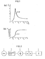
- the curve of Fig.la shows the amplitude profile of a damped vibrating, unbalanced rotor, with the ratio ⁇ of excitation angular frequency Q of the unbalanced rotor to the natural angular frequency we of the rotor plotted on the abscissa and the ratio of vibration path vector X to center of gravity y on the ordinate are.
- the damping D is 0.1.
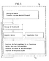
- a grinding wheel 1 is shown from a grinding machine (not shown in more detail), the imbalances which arise during the grinding operation are continuously compensated for in successive compensating processes.
- the vibrations caused by the unbalance of the grinding wheel 1 are detected via a transmission link 5 by a measuring transducer 2, in particular an acceleration sensor, and are forwarded to measuring and control electronics 3 in the form of corresponding measuring signals.
- This electronics is composed of measuring electronics 3a, in which the unbalance of the grinding wheel 1 is continuously determined over the entire speed range of the grinding wheel according to size and direction, and a downstream evaluation and control electronics 3b, in which, depending on the respectively determined unbalance values
- a valve device 4 of a compensation device known from DE-OS 23 57 629 for example, but not shown in the figure, is actuated.
- phase difference (phase shift ⁇ ) between the unbalance angular position when the vibrations triggered by the rotor imbalance are detected in the transmission path 5 and the oscillating movement triggered by this and the machine-related amplitude transmission error in the transmission path 5 are determined as follows after the measurement signals 3a emitted by the measurement transmitter 2 have been detected by the measurement electronics 3a in the evaluation electronics 3b, which can be, for example, a computer, and then for the corresponding control of the valves of the valve device 4 used.
- the values of the initial unbalance which are still affected by the phase error and amplitude error, are used to determine the balance of the test liquid and the angular position of the chamber into which the test liquid was introduced, as well as the measured residual unbalance the introduction of the test quantity of the compensation liquid, the amplitude errors and the phase errors in the transmission Route 5 determined and used in the dimensioning of the compensation amount with which the residual unbalance is compensated.
- the scaling factor for the phase shift is saved and can be used to determine the phase delay in the subsequent unbalance compensation process.
- the corresponding valve or the corresponding valves of the valve device 4 is then opened for a certain period of time, so that the corresponding equalizing amount of the equalizing liquid is introduced into the corresponding equalizing chamber or corresponding equalizing chambers.
Landscapes
- Physics & Mathematics (AREA)
- General Physics & Mathematics (AREA)
- Testing Of Balance (AREA)
- Constituent Portions Of Griding Lathes, Driving, Sensing And Control (AREA)
- Grinding Of Cylindrical And Plane Surfaces (AREA)
Priority Applications (1)
| Application Number | Priority Date | Filing Date | Title |
|---|---|---|---|
| AT85112576T ATE45425T1 (de) | 1985-02-04 | 1985-10-04 | Verfahren zum fortlaufenden ausgleich einer unwucht eines rotors, insbesondere einer schleifscheibe. |
Applications Claiming Priority (2)
| Application Number | Priority Date | Filing Date | Title |
|---|---|---|---|
| DE3503724 | 1985-02-04 | ||
| DE19853503724 DE3503724A1 (de) | 1985-02-04 | 1985-02-04 | Verfahren zum fortlaufenden ausgleich einer unwucht eines rotors, insbesondere einer schleifscheibe |
Publications (3)
| Publication Number | Publication Date |
|---|---|
| EP0190397A2 true EP0190397A2 (fr) | 1986-08-13 |
| EP0190397A3 EP0190397A3 (en) | 1987-12-23 |
| EP0190397B1 EP0190397B1 (fr) | 1989-08-09 |
Family
ID=6261612
Family Applications (1)
| Application Number | Title | Priority Date | Filing Date |
|---|---|---|---|
| EP85112576A Expired EP0190397B1 (fr) | 1985-02-04 | 1985-10-04 | Méthode pour la compensation continue d'un déséquilibre d'un rotor, spécialement d'une meule |
Country Status (5)
| Country | Link |
|---|---|
| US (1) | US4637171A (fr) |
| EP (1) | EP0190397B1 (fr) |
| JP (1) | JPS61178175A (fr) |
| AT (1) | ATE45425T1 (fr) |
| DE (1) | DE3503724A1 (fr) |
Families Citing this family (14)
| Publication number | Priority date | Publication date | Assignee | Title |
|---|---|---|---|---|
| EP0305522A4 (en) * | 1987-03-19 | 1990-09-26 | Lipetsky Stankostroitelny Zavod | Device for automatic balancing of abrasive disks |
| JPH074761B2 (ja) * | 1987-07-31 | 1995-01-25 | オークマ株式会社 | 回転体の不つりあい補正方法 |
| JP2899673B2 (ja) * | 1988-05-28 | 1999-06-02 | ナガセインテグレックス | 回転体のオートバランサー用制御装置 |
| DE3821239C2 (de) * | 1988-06-23 | 1996-10-24 | Dittel Walter Gmbh | Verfahren zum Auswuchten von rotierenden Teilen und Vorrichtung zur Durchführung des Verfahrens |
| US4977510A (en) * | 1989-07-21 | 1990-12-11 | 501 Balance Dynamics Corporation | Computerized control system and method for balancers |
| JP2828346B2 (ja) * | 1990-12-27 | 1998-11-25 | アスモ株式会社 | 回転体の動釣合修正方法および装置 |
| US5343408A (en) * | 1991-08-09 | 1994-08-30 | Industrial Technology Research Institute | Device for on-line automatic fluid injection balancing system |
| US5354186A (en) * | 1993-08-12 | 1994-10-11 | The Board Of Regents Of The University Of Michigan | Machine balancer with peristaltic fluid pump |
| IT1274498B (it) * | 1995-05-12 | 1997-07-17 | Balance Systems Srl | Dispositivo e procedimento di comando e controllo per una macchina rettificatrice |
| DE19700258C2 (de) * | 1997-01-07 | 1999-04-08 | Deutsche Bahn Ag | Verfahren zum Auswuchten von Dieselgeneratoren für Lokomotiven mit einseitiger Lagerung des Generators, bei dem eine Resonanz im Bereich der Betriebsdrehzahlen auftritt |
| DE19729172C1 (de) * | 1997-07-08 | 1998-07-30 | Hofmann Mes Und Auswuchttechni | Verfahren zum fortlaufenden Ausgleich einer Unwucht eines Rotors |
| EP1110733A1 (fr) | 1999-12-20 | 2001-06-27 | Xerox Corporation | Imprimante à jet d'encre comprenant une tête d'impression et une méthode d'évacuation de bulles des têtes d'impression |
| DE10032600B4 (de) * | 2000-07-07 | 2014-02-13 | Brüel & Kjaer Vibro GmbH | Verfahren und Vorrichtung zum Auswuchten eines Rotors |
| CN115575038B (zh) * | 2022-11-24 | 2023-04-07 | 中国航发沈阳发动机研究所 | 一种减小压气机转子旋转惯性激励的控制方法 |
Family Cites Families (3)
| Publication number | Priority date | Publication date | Assignee | Title |
|---|---|---|---|---|
| DE2357629A1 (de) * | 1973-11-19 | 1975-05-28 | Hofmann Maschf Geb | Vorrichtung zum ausgleich der unwucht eines rotierenden koerpers, insbesondere einer schleifscheibe |
| DE7341264U (de) * | 1973-11-19 | 1975-05-15 | Gebr Hofmann Kg | Vorrichtung zum Ausgleich der Unwucht eines rotierenden Körpers, insbesondere einer Schleifscheibe |
| GB2097101B (en) * | 1981-04-20 | 1984-11-14 | Kerlin Jack Harnsworth | Unbalance compensator and method of distributing balancing mass in same |
-
1985
- 1985-02-04 DE DE19853503724 patent/DE3503724A1/de active Granted
- 1985-10-04 EP EP85112576A patent/EP0190397B1/fr not_active Expired
- 1985-10-04 AT AT85112576T patent/ATE45425T1/de not_active IP Right Cessation
-
1986
- 1986-01-30 JP JP61020012A patent/JPS61178175A/ja active Pending
- 1986-02-03 US US06/825,146 patent/US4637171A/en not_active Expired - Lifetime
Also Published As
| Publication number | Publication date |
|---|---|
| DE3503724C2 (fr) | 1988-06-23 |
| ATE45425T1 (de) | 1989-08-15 |
| DE3503724A1 (de) | 1986-08-07 |
| EP0190397A3 (en) | 1987-12-23 |
| JPS61178175A (ja) | 1986-08-09 |
| EP0190397B1 (fr) | 1989-08-09 |
| US4637171A (en) | 1987-01-20 |
Similar Documents
| Publication | Publication Date | Title |
|---|---|---|
| EP0190397B1 (fr) | Méthode pour la compensation continue d'un déséquilibre d'un rotor, spécialement d'une meule | |
| EP1247613B1 (fr) | Système d'actionnement d'une charge dans une machine, avec une pièce de réaction | |
| DE69008633T2 (de) | Gerät zur Erzeugung von Massenkraft. | |
| EP3153277B1 (fr) | Tete d'usinage dotee d'un dispositif d'equilibrage | |
| DE69027913T2 (de) | Gerät zur Erfassung von Bearbeitungsbedingungen in einer Werkzeugmaschine | |
| DE3337846A1 (de) | Verfahren und vorrichtung zur schwingungsschleifendbearbeitung einer profilierten werkstueckoberflaeche | |
| EP0590169B1 (fr) | Procédé pour la détermination du balourd d'un rotor inflexible entraîné en rotation | |
| DE3044440C2 (fr) | ||
| EP0417414B1 (fr) | Méthode et dispositifs pour compenser le déséquilibre d'une meule | |
| DE2518503C2 (fr) | ||
| KR970704587A (ko) | 불평형 질량 진동기 상의 가로 진동을 보상하기 위한 장치 및 방법(compensation for transverse vibrations in unbalanced mass vibrators) | |
| DE10054689C1 (de) | Verfahren zur Beseitigung einer Unwucht eines rotierenden Werkstückes | |
| EP0922528B1 (fr) | Porte outil pour outil rotatif, permettant un réglage radial continu de l'outil | |
| DE19813881C2 (de) | Vorrichtung zur Ermittlung einer Unwucht eines mit einer Antriebseinrichtung in Drehung versetzten Rotors einer Zentrifuge | |
| EP0195845A2 (fr) | Procédé d'équilibrage d'une façon permanente d'un rotor, en particulier d'une molette et arrangement de circuit à cet effet | |
| DE2712029A1 (de) | Nocken(wellen)schleifmaschine | |
| DE69421094T2 (de) | Schleifverfahren und vorrichtung | |
| DE2908272C2 (de) | Vorrichtung zum Auswuchten von Rotoren | |
| DE4214712A1 (de) | Vorrichtung und verfahren zum aufspueren von unwuchtkraft und ort durch frequenzmodulation | |
| DE2612911A1 (de) | Verfahren und vorrichtung zur pruefung von waelzlagern | |
| SU1151371A1 (ru) | Способ расточки | |
| DE2645403B1 (de) | Einrichtung zum Pruefen von Schwingungsdaempfern eines Fahrzeuges | |
| SU1110604A1 (ru) | Устройство дл обработки деталей | |
| SU1722793A1 (ru) | Устройство дл совмещенной обработки резанием и поверхностным пластическим деформированием | |
| DE102008057069A1 (de) | Unwuchtbeseitigung |
Legal Events
| Date | Code | Title | Description |
|---|---|---|---|
| PUAI | Public reference made under article 153(3) epc to a published international application that has entered the european phase |
Free format text: ORIGINAL CODE: 0009012 |
|
| AK | Designated contracting states |
Kind code of ref document: A2 Designated state(s): AT BE CH FR GB IT LI NL |
|
| PUAL | Search report despatched |
Free format text: ORIGINAL CODE: 0009013 |
|
| AK | Designated contracting states |
Kind code of ref document: A3 Designated state(s): AT BE CH FR GB IT LI NL |
|
| RHK1 | Main classification (correction) |
Ipc: G01M 1/32 |
|
| 17P | Request for examination filed |
Effective date: 19880126 |
|
| 17Q | First examination report despatched |
Effective date: 19881206 |
|
| RBV | Designated contracting states (corrected) |
Designated state(s): AT CH FR GB IT LI |
|
| GRAA | (expected) grant |
Free format text: ORIGINAL CODE: 0009210 |
|
| AK | Designated contracting states |
Kind code of ref document: B1 Designated state(s): AT CH FR GB IT LI |
|
| REF | Corresponds to: |
Ref document number: 45425 Country of ref document: AT Date of ref document: 19890815 Kind code of ref document: T |
|
| ITF | It: translation for a ep patent filed | ||
| ET | Fr: translation filed | ||
| GBT | Gb: translation of ep patent filed (gb section 77(6)(a)/1977) | ||
| PLBE | No opposition filed within time limit |
Free format text: ORIGINAL CODE: 0009261 |
|
| STAA | Information on the status of an ep patent application or granted ep patent |
Free format text: STATUS: NO OPPOSITION FILED WITHIN TIME LIMIT |
|
| 26N | No opposition filed | ||
| ITTA | It: last paid annual fee | ||
| REG | Reference to a national code |
Ref country code: CH Ref legal event code: PUE Owner name: HOFMANN WERKSTATT-TECHNIK GMBH TRANSFER- HOFMANN M |
|
| REG | Reference to a national code |
Ref country code: FR Ref legal event code: TP |
|
| REG | Reference to a national code |
Ref country code: GB Ref legal event code: 732E |
|
| PGFP | Annual fee paid to national office [announced via postgrant information from national office to epo] |
Ref country code: FR Payment date: 19971027 Year of fee payment: 13 |
|
| PGFP | Annual fee paid to national office [announced via postgrant information from national office to epo] |
Ref country code: AT Payment date: 19971031 Year of fee payment: 13 |
|
| PG25 | Lapsed in a contracting state [announced via postgrant information from national office to epo] |
Ref country code: AT Free format text: LAPSE BECAUSE OF NON-PAYMENT OF DUE FEES Effective date: 19981004 |
|
| PGFP | Annual fee paid to national office [announced via postgrant information from national office to epo] |
Ref country code: GB Payment date: 19981006 Year of fee payment: 14 |
|
| REG | Reference to a national code |
Ref country code: CH Ref legal event code: PUE Owner name: HOFMANN MASCHINENBAU GMBH TRANSFER- SCHMITT-HOFMAN |
|
| REG | Reference to a national code |
Ref country code: GB Ref legal event code: 732E |
|
| PGFP | Annual fee paid to national office [announced via postgrant information from national office to epo] |
Ref country code: CH Payment date: 19981106 Year of fee payment: 14 |
|
| PG25 | Lapsed in a contracting state [announced via postgrant information from national office to epo] |
Ref country code: FR Free format text: LAPSE BECAUSE OF NON-PAYMENT OF DUE FEES Effective date: 19990630 |
|
| REG | Reference to a national code |
Ref country code: FR Ref legal event code: ST |
|
| PG25 | Lapsed in a contracting state [announced via postgrant information from national office to epo] |
Ref country code: GB Free format text: LAPSE BECAUSE OF NON-PAYMENT OF DUE FEES Effective date: 19991004 |
|
| PG25 | Lapsed in a contracting state [announced via postgrant information from national office to epo] |
Ref country code: LI Free format text: LAPSE BECAUSE OF NON-PAYMENT OF DUE FEES Effective date: 19991031 Ref country code: CH Free format text: LAPSE BECAUSE OF NON-PAYMENT OF DUE FEES Effective date: 19991031 |
|
| GBPC | Gb: european patent ceased through non-payment of renewal fee |
Effective date: 19991004 |
|
| REG | Reference to a national code |
Ref country code: CH Ref legal event code: PL |