EP0190500A2 - Isolation d'un conducteur électrique - Google Patents
Isolation d'un conducteur électrique Download PDFInfo
- Publication number
- EP0190500A2 EP0190500A2 EP85309080A EP85309080A EP0190500A2 EP 0190500 A2 EP0190500 A2 EP 0190500A2 EP 85309080 A EP85309080 A EP 85309080A EP 85309080 A EP85309080 A EP 85309080A EP 0190500 A2 EP0190500 A2 EP 0190500A2
- Authority
- EP
- European Patent Office
- Prior art keywords
- conductor
- orifice
- outlet orifice
- die
- feedpath
- Prior art date
- Legal status (The legal status is an assumption and is not a legal conclusion. Google has not performed a legal analysis and makes no representation as to the accuracy of the status listed.)
- Ceased
Links
Images

Classifications
-
- H—ELECTRICITY
- H01—ELECTRIC ELEMENTS
- H01B—CABLES; CONDUCTORS; INSULATORS; SELECTION OF MATERIALS FOR THEIR CONDUCTIVE, INSULATING OR DIELECTRIC PROPERTIES
- H01B13/00—Apparatus or processes specially adapted for manufacturing conductors or cables
- H01B13/06—Insulating conductors or cables
- H01B13/14—Insulating conductors or cables by extrusion
-
- B—PERFORMING OPERATIONS; TRANSPORTING
- B29—WORKING OF PLASTICS; WORKING OF SUBSTANCES IN A PLASTIC STATE IN GENERAL
- B29C—SHAPING OR JOINING OF PLASTICS; SHAPING OF MATERIAL IN A PLASTIC STATE, NOT OTHERWISE PROVIDED FOR; AFTER-TREATMENT OF THE SHAPED PRODUCTS, e.g. REPAIRING
- B29C48/00—Extrusion moulding, i.e. expressing the moulding material through a die or nozzle which imparts the desired form; Apparatus therefor
- B29C48/03—Extrusion moulding, i.e. expressing the moulding material through a die or nozzle which imparts the desired form; Apparatus therefor characterised by the shape of the extruded material at extrusion
- B29C48/06—Rod-shaped
-
- B—PERFORMING OPERATIONS; TRANSPORTING
- B29—WORKING OF PLASTICS; WORKING OF SUBSTANCES IN A PLASTIC STATE IN GENERAL
- B29C—SHAPING OR JOINING OF PLASTICS; SHAPING OF MATERIAL IN A PLASTIC STATE, NOT OTHERWISE PROVIDED FOR; AFTER-TREATMENT OF THE SHAPED PRODUCTS, e.g. REPAIRING
- B29C48/00—Extrusion moulding, i.e. expressing the moulding material through a die or nozzle which imparts the desired form; Apparatus therefor
- B29C48/25—Component parts, details or accessories; Auxiliary operations
- B29C48/30—Extrusion nozzles or dies
- B29C48/32—Extrusion nozzles or dies with annular openings, e.g. for forming tubular articles
- B29C48/325—Extrusion nozzles or dies with annular openings, e.g. for forming tubular articles being adjustable, i.e. having adjustable exit sections
- B29C48/327—Extrusion nozzles or dies with annular openings, e.g. for forming tubular articles being adjustable, i.e. having adjustable exit sections with centering means
-
- B—PERFORMING OPERATIONS; TRANSPORTING
- B29—WORKING OF PLASTICS; WORKING OF SUBSTANCES IN A PLASTIC STATE IN GENERAL
- B29C—SHAPING OR JOINING OF PLASTICS; SHAPING OF MATERIAL IN A PLASTIC STATE, NOT OTHERWISE PROVIDED FOR; AFTER-TREATMENT OF THE SHAPED PRODUCTS, e.g. REPAIRING
- B29C48/00—Extrusion moulding, i.e. expressing the moulding material through a die or nozzle which imparts the desired form; Apparatus therefor
- B29C48/25—Component parts, details or accessories; Auxiliary operations
- B29C48/30—Extrusion nozzles or dies
- B29C48/32—Extrusion nozzles or dies with annular openings, e.g. for forming tubular articles
- B29C48/34—Cross-head annular extrusion nozzles, i.e. for simultaneously receiving moulding material and the preform to be coated
-
- B—PERFORMING OPERATIONS; TRANSPORTING
- B29—WORKING OF PLASTICS; WORKING OF SUBSTANCES IN A PLASTIC STATE IN GENERAL
- B29C—SHAPING OR JOINING OF PLASTICS; SHAPING OF MATERIAL IN A PLASTIC STATE, NOT OTHERWISE PROVIDED FOR; AFTER-TREATMENT OF THE SHAPED PRODUCTS, e.g. REPAIRING
- B29C48/00—Extrusion moulding, i.e. expressing the moulding material through a die or nozzle which imparts the desired form; Apparatus therefor
- B29C48/25—Component parts, details or accessories; Auxiliary operations
- B29C48/92—Measuring, controlling or regulating
-
- B—PERFORMING OPERATIONS; TRANSPORTING
- B29—WORKING OF PLASTICS; WORKING OF SUBSTANCES IN A PLASTIC STATE IN GENERAL
- B29C—SHAPING OR JOINING OF PLASTICS; SHAPING OF MATERIAL IN A PLASTIC STATE, NOT OTHERWISE PROVIDED FOR; AFTER-TREATMENT OF THE SHAPED PRODUCTS, e.g. REPAIRING
- B29C2948/00—Indexing scheme relating to extrusion moulding
- B29C2948/92—Measuring, controlling or regulating
- B29C2948/92009—Measured parameter
- B29C2948/92114—Dimensions
-
- B—PERFORMING OPERATIONS; TRANSPORTING
- B29—WORKING OF PLASTICS; WORKING OF SUBSTANCES IN A PLASTIC STATE IN GENERAL
- B29C—SHAPING OR JOINING OF PLASTICS; SHAPING OF MATERIAL IN A PLASTIC STATE, NOT OTHERWISE PROVIDED FOR; AFTER-TREATMENT OF THE SHAPED PRODUCTS, e.g. REPAIRING
- B29C2948/00—Indexing scheme relating to extrusion moulding
- B29C2948/92—Measuring, controlling or regulating
- B29C2948/92323—Location or phase of measurement
- B29C2948/92438—Conveying, transporting or storage of articles
Definitions
- This invention relates to the insulating of electrical conductors.
- electrical conductor In the provision of an insulating layer upon an electrical conductor wire (referred to herein as "electrical conductor"), it is conventional practice to feed the conductor through an extruder orifice while surrounding it with elastomeric extrudate which after cooling forms a dielectric material.
- a problem with coating a conductor in this manner is that it is extremely difficult to locate and to hold the conductor concentrically disposed within the extrudate during the coating procedure.
- Known conductor position adjustment apparatus is not sufficiently sensitive in operation to provide a substantially continuous concentricity of conductor and extrudate, particularly as in the case of conductor insulation, the insulation is extremely thin, e.g. around 7 mm for 22 or 24 AWG conductor wire. This thickness allows for a tolerance only of the order of ⁇ 0.0001 inches.
- Such apparatus is suitable for providing substantial concentricity of a core within a jacket, because the tolerance for the location of the core within the jacket may be of the order of ⁇ 0.0002 inches for a thickness of around 40 mil.
- the differences in diameter between the jacket and a conductor insulation layer is such that the apparatus referred to in the copending applications while being suitable for providing concentricity of a core, would not provide sufficiently small degrees of movement or control for concentrically locating a conductor within a small thickness insulation layer.
- the present invention is concerned with a method and apparatus for providing an insulation layer upon an electrical conductor in the use of which substantial concentricity of the conductor within the layer is achieved.
- a method of forming an insulation layer upon an electrical conductor comprising: passing the conductor along a feedpath, with clearance, towards an outlet orifice of a die insert and also with clearance, through the outlet orifice while lying in contact with a part; only of a surface of the insert which defines the orifice and passing the conductor through a die orifice to extrude onto it elastomeric material for forming the layer; monitoring the radial position of the conductor within the layer; and controllably moving the conductor laterally of its feedpath at a position upsstream from the outlet orifice of the die insert dependent upon the eccentricity of the conductor within the layer so as to cause the conductor to change its angle of approach to the outlet orifice and alter the angle of departure of the conductor from the outlet orifice and hence alter its lateral position within the die orifice.
- apparatus for forming an insulating layer upon an electrical conductor comprising an extruder having an extruder head provided with a die orifice and a die insert within the head, the insert having an outlet orifice for passage of the conductor along its feedpath towards the die orifice, and upstream of the otlet orifice, the apparatus defines a passage of larger section than the outlet orifice to allow for lateral clearance,for the conductor on its feedpath, monitoring means to monitor the radial position of the conductor within the layer, and means to controllably move the conductor laterally of its feedpath within the larger section passage so as to change the angle of approach of the conductor towards the outlet orifice.
- apparatus for forming an insulating layer upon an electrical conductor comprises.an extruder 10 in line with a cooling trough 12 for the applied insulation, a capstan 14 and takeup device 16. All of these parts of the apparatus are conventional except for the extruder head which is now to be described.
- the extruder comprises an extruder head 18 which as shown by Figures 2 and 3, comprises a housing 20 with a substantially cylindrical chamber 22 within which is disposed a die insert 24.
- the die insert is a hollow member formed with a bore or passage 36, as shown by Figures 2 and 3, and extends along the feedpath for a conductor 26 as it is fed through the extruder.
- a downstream end 28 of the insert is tapered and is formed directly at the end with an outlet orifice 30 which lies adjacent to a die orifice 32 of the extruder head.
- the die orifice 32 is connected with the extruder in conventional fashion by passageways 34 which extend into the head and surround the tapered portion 28 of the die insert.
- the die insert is in a fixed position within the head with its outlet orifice 30 substantially aligned with the die orifice 32.
- the passage 36 in the die insert 28 has a diameter substantially greater than the diameter of the outlet orifice 30 and the bore and the outlet orifice merge together along the tapered section 28.
- Means 38 is provided to controllably move the conductor laterally of its feedpath at a position upstream from the outlet orifice 30.
- the means 38 is disposed directly upstream from the extruder head 18.
- the means 38 comprises a fixed rectangular frame formed by vertically spaced upper and lower horizontally disposed frame members 40 and 42 between which are disposed two horizontally spaced vertical guides 44.
- On the two guides 44 is mounted a vertically displaceable mounting member 46, the vertical position of which is controlled by a stepper motor 48 secured to the frame member 42.
- the stepper motor 48 is operably connected to the mounting member 46 by gearing 50 which is connected to a screw threaded shaft 52 connected to the mounting member 46. Rotating of the stepper motor in one direction or the other, results in the vertical movement of the mounting member in the appropriate direction.
- a conductor position control member 54 which is formed with guide surface, i.e. an orifice 56 for comfortable passage of the conductor 26.
- the control member 54 54 is mounted for horizontal movement upon horizontal guides 58 secured to the mounting member 46.
- the control member 54 is moved horizontally by a stepper motor 60 which is secured to the mounting member 46 and which is drivably connected to the control member by a screw threaded drive shaft 62 connected to the control member through suitable gearing not shown.
- the mounting member 46 is formed with a horizontal slot 64 through which the orifice 56 is directed at any position of the control member 54.
- the conductor 26 may pass through the orifice 56 at any position of the mounting member 46 or of the control member 54 without interfering with any part of the means 38 except for the sides of the orifice 56.
- a conventional means 66 for measuring, at spaced intervals around the conductor circumference, the thickness of the layer of insulation formed on the conductor.
- the measuring means 66 provides a means for monitoring the radial position of the conductor within the layer.
- the measuring means 66 is of well known construction and may be of a laser or beta gau-ge measuring type.
- electrical signals are sent to a control in the form of a microprocesser 68. These signals are compared with one another and with a data signal corresponding to the desired thickness of the insulation.
- the computer Upon signal comparison if it is clear that parts of the insulation are thicker than others, then the computer generates a signal which is sent to the appropriate stepper motor 48 or 60.
- Appropriate movement of the control member 54 of mounting member 46 moves orifice 56 either vertically or horizontally or both, as the case may be, to have an effect on the position of the conductor as it passes through the die orifice 32.
- the die insert with its outlet orifice 30 controls the position of the conductor 26 in a non-conventional fashion.
- sufficient clearance is provided by an outlet orifice having a diameter which is approximately 0.0005 mil greater than the diameter of the conductor.
- the central position for the feedpath is shown at 69 and theoretically this is the ideal position for the conductor to move along on its way through the die orifice.
- the die insert may not be absolutely concentrically disposed with regard to the die orifice which may account for some eccentricity of the conductor within the finished insulating layer.
- the extrudate in moving through the passage 34 towards the die orifice 32 surrounds the die insert in the passage 34 as shown by Figure 2 before movement towards the die orifice. Movement of the extrudate in this fashion is to some degree uncontrollable, and various forces are involved caused by the flow of the material such that lateral loadings in unspecified directions may be applied to the conductor upon it coming into contact with the extrudate at the die orifice. Such forces also play a part in displacing the conductor from its true concentric position.
- the conductor is passed through the outlet orifice 30 by being held against a surface part 70 of the insert which defines the outlet orifice 30.
- this involves the location of the conductor within the die insert in a position slightly away from the true central position 69 for the feedpath.
- the conductor therefore approaches the outlet orifice 30 at a certain angle of approach which causes it to contact the die insert surface at part 70 and also causes the conductor to move away from the part 70 at a certain angle of departure.
- This angle of departure dictates the position of the conductor as it moves through the die orifice 32.
- the angle of approach of the conductor towards the outlet orifice 30 should change, then the angle of departure from the orifice will also change.
- a change in the angle of approach may also change the position at which the conductor engages the die insert surface surrounding the outlet orifice 30.
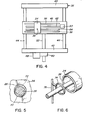
- the conductor may thus move away from contact with part 70 shown in Figure 3 and may contact some other portion of the die insert surface, for instance as shown at 72 in Figure 5.
- the full outline position of the conductor 26 corresponds to the full outline position in Figure 3 whereas the chain dotted outline position in Figure 5 indicates some other position into which the conductor may move after changing angle of approach towards the outlet orifice 30.
- the angle of departure may be such as to dispose the conductor 26 slightly away from a concentric position with the extrudate.
- the movement of the conductor for instance to a chain dotted position 26a in Figure 3 alters its angle of approach towards the outlet orifice. This has the effect of altering its angle of departure through the orifice so that the conductor becomes aligned concentrically with the extrusion orifice to produce a concentrically arranged insulation layer.
- the movement of the conductor in this fashion upon demand is controlled by the means 38.
- the means 66 provides signals to the computer 68 which causes movement of either of the motors 48 or 60 to control the horizontal and vertical position of the orifice 56.
- the conductor is disposed concentrically with the outlet orifice at any particular moment for a certain angle of approach towards the outlet orifice of the die insert, then this is no guarantee that the concentricity will be maintained if the means 38 is not adjusted. Changes in forces by the extrudate upon the conductor may be sufficient to cause slight lateral movement within the die orifice and destroy this concentricity.
- the computer receives signals from the means 66 to cause movement of the member 46 or the control member 54 to reposition the orifice 56 so that a new angle of approach to the outlet orifice is found which will then provide the concentric position of the conductor moving through the die orifice.
- the above apparatus and process are commercially acceptable ways of maintaining concentricity of the conductor within its insulation even though extremely slight degrees of eccentricity are normally found.
- the invention is commercially workable even though it is based on the concept that the conductor need not be perfectly located upon the true concentric feedpath 69 as it moves towards the die orifice.
- the present invention is workable because of the clearance provided between the conductor and the sides of the outlet orifice 30 and because the angle of approach into contact with a part of the sides of the orifice controls the angle of departure from that orifice.
- the method according to the invention may be cohtrolled by a computer arrangement as shown in the first embodiment which involves the use of a position control means such as means 38.
- a position control means such as means 38.
- the invention is operable manually.
- the means 38 is replaced by a simple guide ring 74 which is mounted upon a stand 76 for passage of the conductor through the ring.
- the conductor With the ring disposed in a certain vertical or horizontal location, the conductor makes its approach angle through the die insert 24 and towards the orifice 30 as described in the first embodiment so as to achieve concentricity with the die orifice.
- the means 66 may produce readings upon a display for use by an operator. If these readings are such as to indicate substantial concentricity between the conductor and its insulation then the operator will have no need to interfere with the apparatus.
- the operator merely moves the ring 66 upon the stand 76 in any particular direction so as to adjust the angle of approach of the conductor 26 towards the orifice 30 until he is informed by the display that the conductor is again substantially concentric with the insulation.
Landscapes
- Engineering & Computer Science (AREA)
- Mechanical Engineering (AREA)
- Manufacturing & Machinery (AREA)
- Extrusion Moulding Of Plastics Or The Like (AREA)
- Processes Specially Adapted For Manufacturing Cables (AREA)
Applications Claiming Priority (2)
| Application Number | Priority Date | Filing Date | Title |
|---|---|---|---|
| CA000473456A CA1222362A (fr) | 1985-02-01 | 1985-02-01 | Gainage d'un conducteur electrique avec un isolant |
| CA473456 | 1985-02-01 |
Publications (2)
| Publication Number | Publication Date |
|---|---|
| EP0190500A2 true EP0190500A2 (fr) | 1986-08-13 |
| EP0190500A3 EP0190500A3 (fr) | 1987-08-12 |
Family
ID=4129742
Family Applications (1)
| Application Number | Title | Priority Date | Filing Date |
|---|---|---|---|
| EP85309080A Ceased EP0190500A3 (fr) | 1985-02-01 | 1985-12-13 | Isolation d'un conducteur électrique |
Country Status (3)
| Country | Link |
|---|---|
| EP (1) | EP0190500A3 (fr) |
| JP (1) | JPS61181014A (fr) |
| CA (1) | CA1222362A (fr) |
Cited By (1)
| Publication number | Priority date | Publication date | Assignee | Title |
|---|---|---|---|---|
| WO1997025725A3 (fr) * | 1996-01-04 | 1997-10-30 | Gen Cable Ind Inc | Cable electrique jumele a transmissivite amelioree et procede de fabrication |
Families Citing this family (1)
| Publication number | Priority date | Publication date | Assignee | Title |
|---|---|---|---|---|
| CN117001976B (zh) * | 2023-07-31 | 2024-02-09 | 浙江吴越电缆有限公司 | 一种电缆绝缘层用挤塑机 |
Family Cites Families (3)
| Publication number | Priority date | Publication date | Assignee | Title |
|---|---|---|---|---|
| DE1157682B (de) * | 1953-12-04 | 1963-11-21 | Elektro Schmitz O H G | Regelvorrichtung fuer Kabelumspritzmaschinen |
| DE2402480C3 (de) * | 1974-01-16 | 1980-04-10 | Aeg-Telefunken Kabelwerke Ag, Rheydt, 4050 Moenchengladbach | Zentrierung eines elektrischen Leiters in einer Isolierhülle |
| US4425292A (en) * | 1981-09-29 | 1984-01-10 | Western Electric Company, Inc. | Hybrid extrusion methods |
-
1985
- 1985-02-01 CA CA000473456A patent/CA1222362A/fr not_active Expired
- 1985-12-13 EP EP85309080A patent/EP0190500A3/fr not_active Ceased
-
1986
- 1986-01-31 JP JP61018290A patent/JPS61181014A/ja active Pending
Cited By (2)
| Publication number | Priority date | Publication date | Assignee | Title |
|---|---|---|---|---|
| WO1997025725A3 (fr) * | 1996-01-04 | 1997-10-30 | Gen Cable Ind Inc | Cable electrique jumele a transmissivite amelioree et procede de fabrication |
| US6254924B1 (en) | 1996-01-04 | 2001-07-03 | General Cable Technologies Corporation | Paired electrical cable having improved transmission properties and method for making same |
Also Published As
| Publication number | Publication date |
|---|---|
| CA1222362A (fr) | 1987-06-02 |
| JPS61181014A (ja) | 1986-08-13 |
| EP0190500A3 (fr) | 1987-08-12 |
Similar Documents
| Publication | Publication Date | Title |
|---|---|---|
| US4605525A (en) | Method for forming insulating electrical conductor | |
| US4708837A (en) | Method and apparatus for insulating electrical conductor | |
| US4093414A (en) | Single die co-extrusion apparatus for insulation | |
| EP0513616B1 (fr) | Tête d'extrusion pour appliquer des revêtements de matériaux polymères à des produits semi-finis à conformation cylindrique allongée | |
| EP0902441B1 (fr) | Câble de communication ayant une gaine striée | |
| US4221756A (en) | Methods of enclosing a plurality of conductors in a partitioned jacket | |
| EP0392393A1 (fr) | Procédé d'étirage de fibres optiques | |
| US4710114A (en) | Apparatus for insulating an electrical conductor | |
| US3261893A (en) | Thermally adjusted casting blade | |
| US4659424A (en) | Manufacture of elongate members of indefinite length | |
| JPH0655989B2 (ja) | 繊維被覆装置 | |
| EP0190500A2 (fr) | Isolation d'un conducteur électrique | |
| CA1221519A (fr) | Garnissage d'un conducteur electrique avec une gaine isolante | |
| US4174935A (en) | Extrusion apparatus for producing elongated core members covered with concentric coatings | |
| US3433858A (en) | Method and apparatus for controlling capacitances in multiwire structures | |
| US4017228A (en) | Apparatus for monitoring cellular dielectric material | |
| US2864126A (en) | Plastics extrusion apparatus | |
| US3263271A (en) | Extrusion apparatus | |
| EP1271565B1 (fr) | Procédé de régulation de la capacité | |
| US3807916A (en) | Motorized die holder | |
| JPH09213146A (ja) | 押出し被覆による多芯平角電線の製造方法および製造装置 | |
| CA1213857A (fr) | Extrudeuse | |
| CA1050711A (fr) | Fabrication de conducteurs isoles | |
| CA1267761A (fr) | Methode et appareil pour isoler les conducteurs electriques | |
| JPH0428506A (ja) | ペレタイザにおける回転カッタ位置調整装置 |
Legal Events
| Date | Code | Title | Description |
|---|---|---|---|
| PUAI | Public reference made under article 153(3) epc to a published international application that has entered the european phase |
Free format text: ORIGINAL CODE: 0009012 |
|
| AK | Designated contracting states |
Kind code of ref document: A2 Designated state(s): DE FR GB SE |
|
| PUAL | Search report despatched |
Free format text: ORIGINAL CODE: 0009013 |
|
| AK | Designated contracting states |
Kind code of ref document: A3 Designated state(s): DE FR GB SE |
|
| 17P | Request for examination filed |
Effective date: 19870918 |
|
| 17Q | First examination report despatched |
Effective date: 19881125 |
|
| STAA | Information on the status of an ep patent application or granted ep patent |
Free format text: STATUS: THE APPLICATION HAS BEEN REFUSED |
|
| 18R | Application refused |
Effective date: 19891224 |
|
| RIN1 | Information on inventor provided before grant (corrected) |
Inventor name: BAXTER, GORDON DOUGLAS |