EP0190955A1 - Flüssigkeitszapfstelle, insbesondere für Krankenhäuser - Google Patents
Flüssigkeitszapfstelle, insbesondere für Krankenhäuser Download PDFInfo
- Publication number
- EP0190955A1 EP0190955A1 EP86400076A EP86400076A EP0190955A1 EP 0190955 A1 EP0190955 A1 EP 0190955A1 EP 86400076 A EP86400076 A EP 86400076A EP 86400076 A EP86400076 A EP 86400076A EP 0190955 A1 EP0190955 A1 EP 0190955A1
- Authority
- EP
- European Patent Office
- Prior art keywords
- fluid
- jacket
- socket
- piston
- fluid distribution
- Prior art date
- Legal status (The legal status is an assumption and is not a legal conclusion. Google has not performed a legal analysis and makes no representation as to the accuracy of the status listed.)
- Granted
Links
- 239000012530 fluid Substances 0.000 title claims abstract description 54
- 230000002093 peripheral effect Effects 0.000 claims description 9
- 230000006835 compression Effects 0.000 claims description 7
- 238000007906 compression Methods 0.000 claims description 7
- 238000004140 cleaning Methods 0.000 description 4
- 230000000694 effects Effects 0.000 description 4
- 238000012423 maintenance Methods 0.000 description 2
- 230000000903 blocking effect Effects 0.000 description 1
- 229940082150 encore Drugs 0.000 description 1
- 238000007689 inspection Methods 0.000 description 1
- 238000012544 monitoring process Methods 0.000 description 1
- 230000000750 progressive effect Effects 0.000 description 1
- 238000007789 sealing Methods 0.000 description 1
Images
Classifications
-
- F—MECHANICAL ENGINEERING; LIGHTING; HEATING; WEAPONS; BLASTING
- F16—ENGINEERING ELEMENTS AND UNITS; GENERAL MEASURES FOR PRODUCING AND MAINTAINING EFFECTIVE FUNCTIONING OF MACHINES OR INSTALLATIONS; THERMAL INSULATION IN GENERAL
- F16L—PIPES; JOINTS OR FITTINGS FOR PIPES; SUPPORTS FOR PIPES, CABLES OR PROTECTIVE TUBING; MEANS FOR THERMAL INSULATION IN GENERAL
- F16L37/00—Couplings of the quick-acting type
- F16L37/28—Couplings of the quick-acting type with fluid cut-off means
- F16L37/38—Couplings of the quick-acting type with fluid cut-off means with fluid cut-off means in only one of two pipe-end fittings
- F16L37/40—Couplings of the quick-acting type with fluid cut-off means with fluid cut-off means in only one of two pipe-end fittings with a lift valve being opened automatically when the coupling is applied
- F16L37/42—Couplings of the quick-acting type with fluid cut-off means with fluid cut-off means in only one of two pipe-end fittings with a lift valve being opened automatically when the coupling is applied the valve having an axial bore communicating with lateral apertures
-
- F—MECHANICAL ENGINEERING; LIGHTING; HEATING; WEAPONS; BLASTING
- F16—ENGINEERING ELEMENTS AND UNITS; GENERAL MEASURES FOR PRODUCING AND MAINTAINING EFFECTIVE FUNCTIONING OF MACHINES OR INSTALLATIONS; THERMAL INSULATION IN GENERAL
- F16L—PIPES; JOINTS OR FITTINGS FOR PIPES; SUPPORTS FOR PIPES, CABLES OR PROTECTIVE TUBING; MEANS FOR THERMAL INSULATION IN GENERAL
- F16L29/00—Joints with fluid cut-off means
- F16L29/02—Joints with fluid cut-off means with a cut-off device in one of the two pipe ends, the cut-off device being automatically opened when the coupling is applied
-
- F—MECHANICAL ENGINEERING; LIGHTING; HEATING; WEAPONS; BLASTING
- F16—ENGINEERING ELEMENTS AND UNITS; GENERAL MEASURES FOR PRODUCING AND MAINTAINING EFFECTIVE FUNCTIONING OF MACHINES OR INSTALLATIONS; THERMAL INSULATION IN GENERAL
- F16L—PIPES; JOINTS OR FITTINGS FOR PIPES; SUPPORTS FOR PIPES, CABLES OR PROTECTIVE TUBING; MEANS FOR THERMAL INSULATION IN GENERAL
- F16L37/00—Couplings of the quick-acting type
- F16L37/60—Couplings of the quick-acting type with plug and fixed wall housing
-
- Y—GENERAL TAGGING OF NEW TECHNOLOGICAL DEVELOPMENTS; GENERAL TAGGING OF CROSS-SECTIONAL TECHNOLOGIES SPANNING OVER SEVERAL SECTIONS OF THE IPC; TECHNICAL SUBJECTS COVERED BY FORMER USPC CROSS-REFERENCE ART COLLECTIONS [XRACs] AND DIGESTS
- Y10—TECHNICAL SUBJECTS COVERED BY FORMER USPC
- Y10T—TECHNICAL SUBJECTS COVERED BY FORMER US CLASSIFICATION
- Y10T137/00—Fluid handling
- Y10T137/598—With repair, tapping, assembly, or disassembly means
- Y10T137/6184—Removable valve with normally disabled supplemental check valve
-
- Y—GENERAL TAGGING OF NEW TECHNOLOGICAL DEVELOPMENTS; GENERAL TAGGING OF CROSS-SECTIONAL TECHNOLOGIES SPANNING OVER SEVERAL SECTIONS OF THE IPC; TECHNICAL SUBJECTS COVERED BY FORMER USPC CROSS-REFERENCE ART COLLECTIONS [XRACs] AND DIGESTS
- Y10—TECHNICAL SUBJECTS COVERED BY FORMER USPC
- Y10T—TECHNICAL SUBJECTS COVERED BY FORMER US CLASSIFICATION
- Y10T137/00—Fluid handling
- Y10T137/6851—With casing, support, protector or static constructional installations
- Y10T137/6966—Static constructional installations
- Y10T137/6969—Buildings
- Y10T137/698—Wall
-
- Y—GENERAL TAGGING OF NEW TECHNOLOGICAL DEVELOPMENTS; GENERAL TAGGING OF CROSS-SECTIONAL TECHNOLOGIES SPANNING OVER SEVERAL SECTIONS OF THE IPC; TECHNICAL SUBJECTS COVERED BY FORMER USPC CROSS-REFERENCE ART COLLECTIONS [XRACs] AND DIGESTS
- Y10—TECHNICAL SUBJECTS COVERED BY FORMER USPC
- Y10T—TECHNICAL SUBJECTS COVERED BY FORMER US CLASSIFICATION
- Y10T137/00—Fluid handling
- Y10T137/8593—Systems
- Y10T137/87917—Flow path with serial valves and/or closures
- Y10T137/88046—Biased valve with external operator
Definitions
- the invention relates to a fluid distribution outlet composed of an outlet body provided with a fluid inlet and means for ensuring the circulation of the fluid between this inlet and a outlet nozzle only when this nozzle is introduced into the socket body.
- the invention relates to a fluid distribution outlet which comprises a jacket, the rear chamber of which can communicate with the fluid inlet and in which slides a piston capable of a circulation channel in the form of a blind hole axial open at the front and radial holes at the rear, this piston being held by the pressure of the fluid in the closed position, for which the radial holes are located in the jacket, against a front stop, while the introduction of the socket endpiece pushes it back into its open position for which the radial holes open into the rear chamber.
- the jacket is integral with the grip body.
- the liner in turn slides in a cylindrical appendage of the socket body between a safety position in which it is held by the pressure of the fluid against a stop safety and an open position for which its chamber communicates by radial bores with a body admission chamber, open position in which it is maintained by a removable socket.
- the removable bushing capable of being traversed by the plug end then also constitutes the front stop of the piston.
- the user has the possibility of dismantling the removable socket when the plug end is not in the active position in the socket, that is to say when it is not being used. .
- the shirt then slides in the appendage of the outlet under the effect of the pressure of the fluid and comes to bear against the safety stop. In this position, it prohibits the circulation of the fluid, and the user can safely proceed to cleaning the rear chamber and the cylindrical part of the jacket on the one hand, as well as the parts which he has extracted from on the other hand, namely the piston and the bush with their possible accessories.
- seals are provided at the rear of the piston and of the jacket. It has been found to be more efficient to have these seals on the moving parts of the socket because in this way their wear is reduced and their monitoring is easier since these moving parts can be extracted.
- the radial holes open into a peripheral groove.
- Such grooves which can be provided on the piston, on the jacket or on both, facilitate the circulation of the fluid and avoid any need for setting in rotation of the moving parts of the socket.
- the shirt opens into the rear chamber by a chamfer with a slight slope, and when the shirt itself slides in turn in an appendage of the body, this appendage opens out his turn in the admission chamber by a second chamfer with low slope.
- Such chamfers facilitate the movements of the piston in the liner and of this in the appendix, but they have the main effect of greatly reduce wear and tear at the radial holes and peripheral grooves and above all to eliminate practically any wear on the seals.
- the piston seal which comes out of the jacket and enters it each time the socket is used, will in fact never have to pass through a steep area but will on the contrary be guided by the chamfer of the shirt. The same advantage is found for the seal of the shirt each time it has to leave the appendix or enter it.
- a compression spring is interposed between the bottom of the rear chamber and the bottom of a housing of the piston head and another compression spring is interposed between the bottom of the intake chamber and the bottom of a housing for the head of the shirt when the latter slides into an appendage of the body.
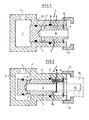
- the socket illustrated in FIG. 1 essentially consists of a socket body 1 forming a cylindrical jacket 2 and a rear chamber 3 provided with a fluid inlet 4.
- a piston 5 in which have been drilled a blind hole 6 opening at the front of the socket, that is to say on the side opposite to the rear chamber and a certain number of radial passages 7 making the blind hole 6 communicate with the external periphery of the piston 5 on which they open in line with a peripheral groove 7 '.
- a circlip has been mounted in a suitable groove in this shirt, constituting a front stop 8 which cooperates with a shoulder. 9 of the piston.
- Two seals 10 and 11 have been disposed respectively, in suitable grooves, at the rear of the piston 5 and in the middle part of the jacket 2.
- the assembly is completed by a locking ring 12 mounted on the front of the shirt 2 in a known manner. It will be recalled that such rings are generally cut so as to be able to cooperate with only one model of nozzle of the type shown in phantom at 13 in FIG. 2.
- Each nozzle comprises a pipe 14 formed here by a blind hole coming from following the blind hole 6, and a radial bore capable of being connected to the conduit for conveying the fluid to the device for use.
- the endpiece 13 also comprises a locking ring 15 cooperating with the locking ring 12.
- FIG. 2 shows a blocking block 16 which the user can, by pushing the piston 5, place between the shoulder 9 of this piston and the front stop 8.
- This wedge ensures the circulation of the fluid for practicing tests or for allowing cleaning since in the position of FIG. 2, which is the open position, the fluid which enters the rear chamber 3 can then circulate in the pipe formed by the radial holes 7 and by the blind hole 6.
- the end piece 13 shown in phantom in Figure 2 can be inserted into the socket so that its crown 15 comes into engagement with the locking ring 12. It then pushes the piston 5 in the same position for which it is seen that the fluid circulates from the inlet 4 through the chamber 3, the radial bores 7, the blind hole 6 and the pipe 14 to the operating circuit, the seal 11 ensuring the sealing of the socket.
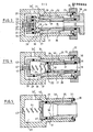
- a piston 17 pierced with a blind hole 18 and radial holes 19 which open into a peripheral groove 20.
- This piston 17 comprises also a front shoulder 21, a seal 22 arranged in a suitable groove at the rear and a housing 2 3 for receiving a compression spring 24.
- the piston 17 is movable inside a jacket 25 provided a rear chamber 26, the cylindrical part of the jacket 25 being connected to the wall of the rear chamber by a slightly sloping chamfer 27.
- the jacket 25 is provided with a front shoulder 28 and, in a suitable groove, a seal 29. It is of course fitted with radial holes 30 opening into a peripheral groove 31.
- the jacket 25 is mounted inside an appendage 32 forming part of the intake body and which ends at the rear by an intake chamber 33 provided with a fluid inlet 33 ′
- the internal periphery of the appendage 32 opens into the inlet chamber by a chamfer with a slight slope 34 similar to the chamfer 27.
- the appendage 32 carries at the front successively a circlip forming a stop 35 arranged in a suitable groove, then a removable socket 36 whose crown is blocked by a nut 37, with the interposition of a suitable gasket 3o. For reasons of.
- FIG. 5 represents the position occupied by the sleeve 25 when the locking nut 37 has been removed and the removable sleeve 36 removed.
- the sleeve 25 thanks to the pressure of the fluid which is exerted in the intake chamber 33, possibly assisted by a compression spring 41, the ends of which are received by a housing 42 provided in the wall of the rear chamber 2 6 of the jacket 2 5 and a housing 43 provided in the rear wall of the inlet chamber 33, caused the shirt 25 to bear by its shoulder 28 on the safety stop 35.
- the closure of the socket is ensured since the fluid present in the inlet chamber 33 is prohibited access to the radial holes 30 thanks to the two cooperating cylindrical surfaces of the appendage 32 and of the jacket 25 and especially thanks to the seal 29.
Landscapes
- General Engineering & Computer Science (AREA)
- Engineering & Computer Science (AREA)
- Mechanical Engineering (AREA)
- Quick-Acting Or Multi-Walled Pipe Joints (AREA)
- External Artificial Organs (AREA)
- Infusion, Injection, And Reservoir Apparatuses (AREA)
- Materials For Medical Uses (AREA)
- Internal Circuitry In Semiconductor Integrated Circuit Devices (AREA)
- Accommodation For Nursing Or Treatment Tables (AREA)
- Pharmaceuticals Containing Other Organic And Inorganic Compounds (AREA)
- Acyclic And Carbocyclic Compounds In Medicinal Compositions (AREA)
- Connector Housings Or Holding Contact Members (AREA)
- Executing Machine-Instructions (AREA)
- Flow Control (AREA)
- Self-Closing Valves And Venting Or Aerating Valves (AREA)
- Massaging Devices (AREA)
Priority Applications (1)
| Application Number | Priority Date | Filing Date | Title |
|---|---|---|---|
| AT86400076T ATE39740T1 (de) | 1985-01-18 | 1986-01-15 | Fluessigkeitszapfstelle, insbesondere fuer krankenhaeuser. |
Applications Claiming Priority (2)
| Application Number | Priority Date | Filing Date | Title |
|---|---|---|---|
| FR8500681A FR2576385B1 (fr) | 1985-01-18 | 1985-01-18 | Prise de distribution de fluides, en particulier pour etablissements hospitaliers |
| FR8500681 | 1985-01-18 |
Publications (2)
| Publication Number | Publication Date |
|---|---|
| EP0190955A1 true EP0190955A1 (de) | 1986-08-13 |
| EP0190955B1 EP0190955B1 (de) | 1989-01-04 |
Family
ID=9315390
Family Applications (1)
| Application Number | Title | Priority Date | Filing Date |
|---|---|---|---|
| EP86400076A Expired EP0190955B1 (de) | 1985-01-18 | 1986-01-15 | Flüssigkeitszapfstelle, insbesondere für Krankenhäuser |
Country Status (19)
| Country | Link |
|---|---|
| US (1) | US4683905A (de) |
| EP (1) | EP0190955B1 (de) |
| JP (1) | JPS61274174A (de) |
| AT (1) | ATE39740T1 (de) |
| AU (1) | AU574039B2 (de) |
| CA (1) | CA1271971A (de) |
| DE (2) | DE190955T1 (de) |
| DK (1) | DK168101B1 (de) |
| ES (1) | ES8705102A1 (de) |
| FI (1) | FI82135C (de) |
| FR (1) | FR2576385B1 (de) |
| IE (1) | IE57313B1 (de) |
| MA (1) | MA20607A1 (de) |
| MC (1) | MC1731A1 (de) |
| NO (1) | NO170780C (de) |
| OA (1) | OA08190A (de) |
| PT (1) | PT81868B (de) |
| TN (1) | TNSN86006A1 (de) |
| ZA (1) | ZA86362B (de) |
Cited By (2)
| Publication number | Priority date | Publication date | Assignee | Title |
|---|---|---|---|---|
| FR2706310A1 (fr) * | 1993-06-11 | 1994-12-23 | Technologie Medicale | Embout équerre indémontable. |
| EP0702187A1 (de) * | 1994-09-16 | 1996-03-20 | Bundy Corporation | Schnellkupplung mit rohrbetätigtem Schnellschlussventil |
Families Citing this family (41)
| Publication number | Priority date | Publication date | Assignee | Title |
|---|---|---|---|---|
| JPS6394373U (de) * | 1986-12-11 | 1988-06-17 | ||
| FR2609522B1 (fr) * | 1987-01-12 | 1989-03-24 | Legris Sa | Boitier destine au passage des fluides sous pression dans la maconnerie |
| US4754780A (en) * | 1987-02-10 | 1988-07-05 | Smith Iii Robert E | Pressure balanced hydraulic coupling |
| US5026025A (en) * | 1988-10-14 | 1991-06-25 | Tokai Rubber Industries, Ltd. | Hose joint with opening-closing valve |
| US5360413A (en) * | 1991-12-06 | 1994-11-01 | Filtertek, Inc. | Needleless access device |
| US5247962A (en) * | 1993-01-14 | 1993-09-28 | Gaddis-Walker Electric, Inc. | Swivel connector for gas service devices in modular gas services unit |
| US5562121A (en) * | 1995-04-06 | 1996-10-08 | Allied Healthcare Products, Inc. | Gas delivery system with universal outlet |
| US5771053A (en) | 1995-12-04 | 1998-06-23 | Hewlett-Packard Company | Assembly for controlling ink release from a container |
| US5815182A (en) | 1995-12-04 | 1998-09-29 | Hewlett-Packard Company | Fluid interconnect for ink-jet pen |
| US5847734A (en) | 1995-12-04 | 1998-12-08 | Pawlowski, Jr.; Norman E. | Air purge system for an ink-jet printer |
| US5900895A (en) | 1995-12-04 | 1999-05-04 | Hewlett-Packard Company | Method for refilling an ink supply for an ink-jet printer |
| DE69728422T2 (de) * | 1996-11-18 | 2005-03-03 | Nypro Inc., Clinton | Abwischbares luer-ventil |
| US7789864B2 (en) | 1996-11-18 | 2010-09-07 | Nypro Inc. | Luer-activated valve |
| US6883778B1 (en) | 1996-11-18 | 2005-04-26 | Nypro Inc. | Apparatus for reducing fluid drawback through a medical valve |
| WO1999066968A2 (en) | 1998-06-24 | 1999-12-29 | Hill-Rom, Inc. | Gas outlet barrel retention apparatus |
| WO2000046531A1 (en) * | 1999-02-03 | 2000-08-10 | Split-Cycle Technology Limited | Improvements in air motors |
| US6189560B1 (en) * | 2000-01-18 | 2001-02-20 | Vitalaire | Connector assembly for medical gas service outlet |
| WO2002034326A2 (en) * | 2000-10-23 | 2002-05-02 | Nypro, Inc. | Anti-drawback medical valve |
| DE60205049T2 (de) * | 2001-03-07 | 2006-04-13 | Max Co. Ltd. | Druckluftversorgungsgerät mit einem Verdichter |
| DE10127977C2 (de) * | 2001-06-08 | 2003-11-27 | Danfoss Analytical As Sonderbo | Schnellkupplungsanordnung |
| JP2005500142A (ja) * | 2001-08-22 | 2005-01-06 | ナイプロ・インク | 拡張部材を備える医療用弁 |
| DE10151995C1 (de) * | 2001-10-22 | 2002-06-27 | Mertik Maxitrol Gmbh & Co Kg | Gassteckdose |
| US7837658B2 (en) | 2001-11-13 | 2010-11-23 | Nypro Inc. | Anti-drawback medical valve |
| US7753892B2 (en) | 2001-11-13 | 2010-07-13 | Nypro Inc. | Anti-drawback medical valve |
| US6869426B2 (en) * | 2001-11-13 | 2005-03-22 | Nypro Inc. | Anti-drawback medical valve |
| US7357792B2 (en) * | 2002-10-29 | 2008-04-15 | Nypro Inc. | Positive push medical valve with internal seal |
| US6767002B2 (en) * | 2002-11-06 | 2004-07-27 | Torrent Trading Ltd. | Check valve |
| DE10312997B3 (de) * | 2003-03-24 | 2004-01-08 | Mertik Maxitrol Gmbh & Co. Kg | Gassteckdose |
| WO2004112866A2 (en) | 2003-06-17 | 2004-12-29 | Filtertek Inc. | Fluid handling device and method of making same |
| US7914502B2 (en) * | 2003-07-31 | 2011-03-29 | Nypro Inc. | Anti-drawback medical valve |
| EP1611921A1 (de) * | 2004-06-29 | 2006-01-04 | Yog Industries | Medizinische Steckdose zur Verwendung medizinischer Flüssigkeiten |
| US7887519B2 (en) | 2005-01-14 | 2011-02-15 | Nypro Inc. | Valve with internal lifter |
| NO328274B1 (no) | 2005-11-29 | 2010-01-18 | Tdw Offshore Services As | Anordning ved kobling |
| US7879012B2 (en) | 2006-04-11 | 2011-02-01 | Nypro Inc. | Medical valve with resilient sealing member |
| US8100869B2 (en) | 2006-08-11 | 2012-01-24 | Nypro Inc. | Medical valve with expandable member |
| ES2696987T3 (es) | 2009-06-22 | 2019-01-21 | Np Medical Inc | Válvula médica con sellado de contrapresión mejorado |
| US9138572B2 (en) | 2010-06-24 | 2015-09-22 | Np Medical Inc. | Medical valve with fluid volume alteration |
| WO2014210028A1 (en) * | 2013-06-24 | 2014-12-31 | Spx Corporation | Pressure balanced hydraulic device and method |
| ITMI20150642A1 (it) * | 2015-05-07 | 2016-11-07 | Alfa Gomma S P A | Innesto rapido femmina innestabile in pressione |
| WO2019040405A1 (en) * | 2017-08-22 | 2019-02-28 | Mistbox, Inc. | AUTOMATIC ANTI-LEAK STOP VALVE |
| EP4065243A4 (de) * | 2019-11-25 | 2024-01-03 | Sprinkler Stop, LLC | Inline-ventil für einen sprinklerkopfersatz |
Citations (2)
| Publication number | Priority date | Publication date | Assignee | Title |
|---|---|---|---|---|
| FR598208A (fr) * | 1925-05-14 | 1925-12-09 | Surth Maschf | Soupape différentielle, en particulier pour hautes pressions |
| FR2323090A1 (fr) * | 1974-01-10 | 1977-04-01 | Air Liquide | Raccord a verrouillage automatique et elements internes demontables pour canalisation de fluide |
Family Cites Families (6)
| Publication number | Priority date | Publication date | Assignee | Title |
|---|---|---|---|---|
| FR389931A (fr) * | 1908-05-06 | 1908-09-22 | Peter Furtner | Accouplement à manche pour conduites de freins à air comprimé |
| US1679736A (en) * | 1922-03-14 | 1928-08-07 | Bassick Mfg Co | Lubricating apparatus |
| US2322168A (en) * | 1942-01-12 | 1943-06-15 | Charles T Smith | Hose coupling |
| US2444889A (en) * | 1946-06-14 | 1948-07-06 | Bruce N Spencer Jr | Safety gas cock |
| US3563267A (en) * | 1968-09-30 | 1971-02-16 | Air Reduction | Gas dispensing double check valve construction |
| SE7709897L (sv) * | 1977-09-02 | 1979-03-03 | Nordin Lars Gunnar | Vexelventil for stromningssystem |
-
1985
- 1985-01-18 FR FR8500681A patent/FR2576385B1/fr not_active Expired
-
1986
- 1986-01-10 IE IE79/86A patent/IE57313B1/en not_active IP Right Cessation
- 1986-01-10 MA MA20832A patent/MA20607A1/fr unknown
- 1986-01-15 EP EP86400076A patent/EP0190955B1/de not_active Expired
- 1986-01-15 US US06/819,029 patent/US4683905A/en not_active Expired - Fee Related
- 1986-01-15 AT AT86400076T patent/ATE39740T1/de not_active IP Right Cessation
- 1986-01-15 DE DE198686400076T patent/DE190955T1/de active Pending
- 1986-01-15 MC MC861817A patent/MC1731A1/fr unknown
- 1986-01-15 DE DE8686400076T patent/DE3661650D1/de not_active Expired
- 1986-01-16 ES ES550929A patent/ES8705102A1/es not_active Expired
- 1986-01-16 NO NO860146A patent/NO170780C/no unknown
- 1986-01-17 PT PT81868A patent/PT81868B/pt not_active IP Right Cessation
- 1986-01-17 TN TNTNSN86006A patent/TNSN86006A1/fr unknown
- 1986-01-17 JP JP61007797A patent/JPS61274174A/ja active Pending
- 1986-01-17 AU AU52515/86A patent/AU574039B2/en not_active Ceased
- 1986-01-17 FI FI860231A patent/FI82135C/fi not_active IP Right Cessation
- 1986-01-17 ZA ZA86362A patent/ZA86362B/xx unknown
- 1986-01-17 DK DK022786A patent/DK168101B1/da not_active IP Right Cessation
- 1986-01-17 OA OA58768A patent/OA08190A/xx unknown
- 1986-01-17 CA CA000499777A patent/CA1271971A/en not_active Expired - Fee Related
Patent Citations (2)
| Publication number | Priority date | Publication date | Assignee | Title |
|---|---|---|---|---|
| FR598208A (fr) * | 1925-05-14 | 1925-12-09 | Surth Maschf | Soupape différentielle, en particulier pour hautes pressions |
| FR2323090A1 (fr) * | 1974-01-10 | 1977-04-01 | Air Liquide | Raccord a verrouillage automatique et elements internes demontables pour canalisation de fluide |
Cited By (2)
| Publication number | Priority date | Publication date | Assignee | Title |
|---|---|---|---|---|
| FR2706310A1 (fr) * | 1993-06-11 | 1994-12-23 | Technologie Medicale | Embout équerre indémontable. |
| EP0702187A1 (de) * | 1994-09-16 | 1996-03-20 | Bundy Corporation | Schnellkupplung mit rohrbetätigtem Schnellschlussventil |
Also Published As
| Publication number | Publication date |
|---|---|
| CA1271971A (en) | 1990-07-24 |
| OA08190A (fr) | 1987-10-30 |
| IE57313B1 (en) | 1992-07-15 |
| NO170780B (no) | 1992-08-24 |
| US4683905A (en) | 1987-08-04 |
| FI82135C (fi) | 1991-01-10 |
| IE860079L (en) | 1986-07-18 |
| DK22786D0 (da) | 1986-01-17 |
| PT81868B (pt) | 1992-05-29 |
| FI860231L (fi) | 1986-07-19 |
| FR2576385B1 (fr) | 1987-07-17 |
| EP0190955B1 (de) | 1989-01-04 |
| FI82135B (fi) | 1990-09-28 |
| TNSN86006A1 (fr) | 1990-01-01 |
| FR2576385A1 (fr) | 1986-07-25 |
| AU574039B2 (en) | 1988-06-23 |
| AU5251586A (en) | 1986-07-24 |
| JPS61274174A (ja) | 1986-12-04 |
| DK22786A (da) | 1986-07-19 |
| ATE39740T1 (de) | 1989-01-15 |
| DE190955T1 (de) | 1987-07-23 |
| DE3661650D1 (en) | 1989-02-09 |
| ES550929A0 (es) | 1987-05-01 |
| MC1731A1 (fr) | 1986-12-15 |
| NO170780C (no) | 1992-12-02 |
| NO860146L (no) | 1986-07-21 |
| ZA86362B (en) | 1986-09-24 |
| FI860231A0 (fi) | 1986-01-17 |
| DK168101B1 (da) | 1994-02-07 |
| MA20607A1 (fr) | 1986-10-01 |
| ES8705102A1 (es) | 1987-05-01 |
| PT81868A (fr) | 1986-02-01 |
Similar Documents
| Publication | Publication Date | Title |
|---|---|---|
| EP0190955B1 (de) | Flüssigkeitszapfstelle, insbesondere für Krankenhäuser | |
| EP0799396B1 (de) | Schnellverbindung mit entkupplung in zwei stufen | |
| CA2754552C (fr) | Dispositif de raccord avec verrouillage par griffes filetees et raccord comprenant un tel dispositif | |
| EP1108443B1 (de) | Stecker mit automatischer Sperrvorrichtung zum Anschliessen eines Injektionsspritzenkopfes an einem Injektionsaustritt | |
| EP0077743B1 (de) | Schnellkupplungen für lösbare Rohrverbindungen von Rohrleitungen | |
| EP0678697B1 (de) | Schnellkupplung zum kontrollierten Trennen von unter Druck stehenden Rohren | |
| FR2503828A1 (fr) | Raccord rapide pour tubes | |
| CH629661A5 (fr) | Piece a main dentaire munie d'un dispositif de reglage des liquides d'arrosage de l'outil. | |
| FR2861159A1 (fr) | Raccord rapide pour la jonction amovible de deux canalisations et utilisation d'un tel raccord | |
| FR2786849A1 (fr) | Raccord rapide de securite pour la jonction amovible de canalisations | |
| EP0308410B1 (de) | Drehbare vorrichtung für untraumatischen zugang zum blutkreislauf | |
| FR2998638A1 (fr) | Raccord | |
| FR2865259A1 (fr) | Raccord rapide et procede de desacouplement des elements male et femelle d'un tel raccord | |
| FR2657143A1 (fr) | Raccord rapide sans fuite de fluide. | |
| EP1085245B1 (de) | Verbindungsmittel für Anschliessen eines Rohres an röhrenförmigen Körper | |
| WO2011039109A1 (fr) | Prise de distribution de fluide | |
| FR2995654A1 (fr) | Prise de raccordement comprenant un corps monobloc logeant un clapet de maintenance et un clapet principal | |
| FR2629706A1 (fr) | Appareil d'injection de liquide, notamment a usage de soins dentaires | |
| CH669910A5 (en) | Syringe with two series of stops on piston - engageable by rotation with slot in cover to allow motion in one direction only | |
| EP2587109A1 (de) | Anschlussvorrichtung | |
| FR2804609A1 (fr) | Dispositif de distribution pour un reseau de transport d'un fluide medical | |
| EP0847511B1 (de) | Schnellkupplung für druckleitungen | |
| FR2693786A1 (fr) | Améliorations introduites aux valves pour fluides. | |
| EP0976419A1 (de) | Verbindungsvorrichtung für eine Peritonealdialyseleitung | |
| FR2833847A1 (fr) | Regulateur de debit pour un ensemble de perfusion intraveineuse, muni de moyens de reception et de protection de l'aiguille de perfusion apres utilisation dudit ensemble de perfusion |
Legal Events
| Date | Code | Title | Description |
|---|---|---|---|
| PUAI | Public reference made under article 153(3) epc to a published international application that has entered the european phase |
Free format text: ORIGINAL CODE: 0009012 |
|
| AK | Designated contracting states |
Kind code of ref document: A1 Designated state(s): AT BE CH DE GB IT LI LU NL SE |
|
| ITCL | It: translation for ep claims filed |
Representative=s name: ING. A. GIAMBROCONO & C. S.R.L. |
|
| TCAT | At: translation of patent claims filed | ||
| 17P | Request for examination filed |
Effective date: 19870112 |
|
| TCNL | Nl: translation of patent claims filed | ||
| DET | De: translation of patent claims | ||
| 17Q | First examination report despatched |
Effective date: 19870817 |
|
| GRAA | (expected) grant |
Free format text: ORIGINAL CODE: 0009210 |
|
| AK | Designated contracting states |
Kind code of ref document: B1 Designated state(s): AT BE CH DE GB IT LI LU NL SE |
|
| REF | Corresponds to: |
Ref document number: 39740 Country of ref document: AT Date of ref document: 19890115 Kind code of ref document: T |
|
| REF | Corresponds to: |
Ref document number: 3661650 Country of ref document: DE Date of ref document: 19890209 |
|
| ITF | It: translation for a ep patent filed | ||
| GBT | Gb: translation of ep patent filed (gb section 77(6)(a)/1977) | ||
| PLBE | No opposition filed within time limit |
Free format text: ORIGINAL CODE: 0009261 |
|
| STAA | Information on the status of an ep patent application or granted ep patent |
Free format text: STATUS: NO OPPOSITION FILED WITHIN TIME LIMIT |
|
| 26N | No opposition filed | ||
| PGFP | Annual fee paid to national office [announced via postgrant information from national office to epo] |
Ref country code: AT Payment date: 19921228 Year of fee payment: 8 |
|
| PGFP | Annual fee paid to national office [announced via postgrant information from national office to epo] |
Ref country code: GB Payment date: 19930108 Year of fee payment: 8 |
|
| PGFP | Annual fee paid to national office [announced via postgrant information from national office to epo] |
Ref country code: LU Payment date: 19930122 Year of fee payment: 8 |
|
| PGFP | Annual fee paid to national office [announced via postgrant information from national office to epo] |
Ref country code: DE Payment date: 19930125 Year of fee payment: 8 |
|
| PGFP | Annual fee paid to national office [announced via postgrant information from national office to epo] |
Ref country code: SE Payment date: 19930126 Year of fee payment: 8 |
|
| ITTA | It: last paid annual fee | ||
| PGFP | Annual fee paid to national office [announced via postgrant information from national office to epo] |
Ref country code: NL Payment date: 19930131 Year of fee payment: 8 |
|
| PGFP | Annual fee paid to national office [announced via postgrant information from national office to epo] |
Ref country code: BE Payment date: 19930211 Year of fee payment: 8 |
|
| PGFP | Annual fee paid to national office [announced via postgrant information from national office to epo] |
Ref country code: CH Payment date: 19930330 Year of fee payment: 8 |
|
| EPTA | Lu: last paid annual fee | ||
| PG25 | Lapsed in a contracting state [announced via postgrant information from national office to epo] |
Ref country code: LU Free format text: LAPSE BECAUSE OF NON-PAYMENT OF DUE FEES Effective date: 19940115 Ref country code: GB Effective date: 19940115 Ref country code: AT Effective date: 19940115 |
|
| PG25 | Lapsed in a contracting state [announced via postgrant information from national office to epo] |
Ref country code: SE Effective date: 19940116 |
|
| PG25 | Lapsed in a contracting state [announced via postgrant information from national office to epo] |
Ref country code: LI Effective date: 19940131 Ref country code: CH Effective date: 19940131 Ref country code: BE Effective date: 19940131 |
|
| BERE | Be: lapsed |
Owner name: S.A. DUFFOUR ET IGON (D.I.) Effective date: 19940131 |
|
| PG25 | Lapsed in a contracting state [announced via postgrant information from national office to epo] |
Ref country code: NL Effective date: 19940801 |
|
| GBPC | Gb: european patent ceased through non-payment of renewal fee |
Effective date: 19940115 |
|
| NLV4 | Nl: lapsed or anulled due to non-payment of the annual fee | ||
| REG | Reference to a national code |
Ref country code: CH Ref legal event code: PL |
|
| PG25 | Lapsed in a contracting state [announced via postgrant information from national office to epo] |
Ref country code: DE Effective date: 19941001 |
|
| EUG | Se: european patent has lapsed |
Ref document number: 86400076.5 Effective date: 19940810 |
|
| PG25 | Lapsed in a contracting state [announced via postgrant information from national office to epo] |
Ref country code: IT Free format text: LAPSE BECAUSE OF NON-PAYMENT OF DUE FEES;WARNING: LAPSES OF ITALIAN PATENTS WITH EFFECTIVE DATE BEFORE 2007 MAY HAVE OCCURRED AT ANY TIME BEFORE 2007. THE CORRECT EFFECTIVE DATE MAY BE DIFFERENT FROM THE ONE RECORDED. Effective date: 20050115 |