EP0191081B1 - Vorrichtung zum vibrieren von baumaterialien für strassendecken während dem aufbringen und verdichten - Google Patents
Vorrichtung zum vibrieren von baumaterialien für strassendecken während dem aufbringen und verdichten Download PDFInfo
- Publication number
- EP0191081B1 EP0191081B1 EP85904258A EP85904258A EP0191081B1 EP 0191081 B1 EP0191081 B1 EP 0191081B1 EP 85904258 A EP85904258 A EP 85904258A EP 85904258 A EP85904258 A EP 85904258A EP 0191081 B1 EP0191081 B1 EP 0191081B1
- Authority
- EP
- European Patent Office
- Prior art keywords
- spread
- vibrating
- box
- spreading
- ground
- Prior art date
- Legal status (The legal status is an assumption and is not a legal conclusion. Google has not performed a legal analysis and makes no representation as to the accuracy of the status listed.)
- Expired - Lifetime
Links
Images


Classifications
-
- E—FIXED CONSTRUCTIONS
- E01—CONSTRUCTION OF ROADS, RAILWAYS, OR BRIDGES
- E01C—CONSTRUCTION OF, OR SURFACES FOR, ROADS, SPORTS GROUNDS, OR THE LIKE; MACHINES OR AUXILIARY TOOLS FOR CONSTRUCTION OR REPAIR
- E01C19/00—Machines, tools or auxiliary devices for preparing or distributing paving materials, for working the placed materials, or for forming, consolidating, or finishing the paving
- E01C19/22—Machines, tools or auxiliary devices for preparing or distributing paving materials, for working the placed materials, or for forming, consolidating, or finishing the paving for consolidating or finishing laid-down unset materials
- E01C19/30—Tamping or vibrating apparatus other than rollers ; Devices for ramming individual paving elements
- E01C19/34—Power-driven rammers or tampers, e.g. air-hammer impacted shoes for ramming stone-sett paving; Hand-actuated ramming or tamping machines, e.g. tampers with manually hoisted dropping weight
- E01C19/40—Power-driven rammers or tampers, e.g. air-hammer impacted shoes for ramming stone-sett paving; Hand-actuated ramming or tamping machines, e.g. tampers with manually hoisted dropping weight adapted to impart a smooth finish to the paving, e.g. tamping or vibrating finishers
- E01C19/407—Power-driven rammers or tampers, e.g. air-hammer impacted shoes for ramming stone-sett paving; Hand-actuated ramming or tamping machines, e.g. tampers with manually hoisted dropping weight adapted to impart a smooth finish to the paving, e.g. tamping or vibrating finishers with elements or parts partly or fully immersed in or penetrating into the material to act thereon, e.g. immersed vibrators or vibrating parts, kneading tampers, spaders
-
- E—FIXED CONSTRUCTIONS
- E01—CONSTRUCTION OF ROADS, RAILWAYS, OR BRIDGES
- E01C—CONSTRUCTION OF, OR SURFACES FOR, ROADS, SPORTS GROUNDS, OR THE LIKE; MACHINES OR AUXILIARY TOOLS FOR CONSTRUCTION OR REPAIR
- E01C19/00—Machines, tools or auxiliary devices for preparing or distributing paving materials, for working the placed materials, or for forming, consolidating, or finishing the paving
- E01C19/48—Machines, tools or auxiliary devices for preparing or distributing paving materials, for working the placed materials, or for forming, consolidating, or finishing the paving for laying-down the materials and consolidating them, or finishing the surface, e.g. slip forms therefor, forming kerbs or gutters in a continuous operation in situ
- E01C19/4833—Machines, tools or auxiliary devices for preparing or distributing paving materials, for working the placed materials, or for forming, consolidating, or finishing the paving for laying-down the materials and consolidating them, or finishing the surface, e.g. slip forms therefor, forming kerbs or gutters in a continuous operation in situ with tamping or vibrating means for consolidating or finishing, e.g. immersed vibrators, with or without non-vibratory or non-percussive pressing or smoothing means
Definitions
- the present invention relates to a device for spreading and vibrating in the mass of pavement materials, of the type comprising a vibrating box formed by two vertical walls and a bottom on which vibrators are fixed, the box being open at its upper part and at an exit zone of the materials, an adjustment system being provided at the exit zone for leveling the surface of the spilled material.
- French patent 625 815 describes such a device in which the box consists of a flat-bottomed box arranged in height which is followed by a funnel or discharge pipe allowing the spreading of concrete.
- this device makes it possible to densify only materials having thixotropic properties.
- Pavement materials are understood to mean all the materials constituting pavements such as gravel, sand, fine soil, mixed with any binder (hydraulic or bituminous) or without binder, with water or without water, or mechanically stabilized.
- Some spreading materials for example the paver or autograde, during the spreading of the material, try to arrange the aggregates together, thus creating a precompaction by vibrating by contact on the upper surface of the layer of materials with either a vibrating formwork or a vibrating table.
- the vibrations thus transmitted to the aggregates are quickly absorbed by the thickness of the material, and only the aggregates near the vibrating surfaces are put in place, arranged and easy to compact.
- the aggregates located in the middle or at the bottom of the layer, little influenced by the surface vibration, are therefore not or little arranged. This makes subsequent compaction difficult at these levels.
- the surface materials are well compacted while those at the bottom of the layer are only weakly compacted. We then observe in the pavement layers thus produced strong density gradients which reduce the performance of the material and the structure.
- the aim of the present invention is to propose a device of the type mentioned above making it possible to better rearrange the aggregates of both thixotropic and non-thixotropic materials for pavement layers (bases, foundation, and of shapes, surface, etc.), during spreading, and pre-compact them to facilitate subsequent compaction of these materials.
- the object is achieved by the fact that the vibrators are mounted in the lower part of the bottom so as to impose on the box an essentially horizontal vibration in the horizontal plane parallel to the surface on which the material is to be spread, and in that the bottom is curved and ends at its lower part with a horizontal part which is in contact with the surface on which the material is to be spread and which makes it possible to vibrate the material spread at the base of the layer.
- FIG. 1 shows a known spreading device
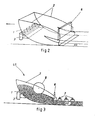
- FIGS. 2 and 3 respectively represent the perspective and the section of a device according to the present invention
- FIGS. 4 and 5 show details of the embodiment of the lower part of the vibrating box.
- the reference 7 represents the vibrating soles or ladies
- the reference 8 the distribution screw
- the reference 9 the vibrating formwork
- the reference 10 the layer of widespread material.
- the device according to the invention consists of a vibrating metal box having a bottom formed by a curved plate 1 and having two side walls 2.
- the box is not closed at its upper part or on the side from which it exits the spilled material.
- the box is vibrated at its base by vibrators 3.
- the lower part of the box in contact with the surface of the ground on which the material is to be spread must be flexible in order to match the unevenness of the ground. It can be carried out for example, either using flexible membranes 4 made of rubber or other flexible material fixed to the box (fig. 4), or by the fact that the bottom 1 ends with blades 5 cut out from the sheet of the bottom 1 (fig. 5).
- the box is partially closed on the side of the spilled material by any system allowing the thickness of the spilled material to be adjusted.
- This can be constituted for example by a vibrating blade 6 adjustable in height according to the desired profile of the widespread layer and independently of the box or by a system of rotating grooved drum.
- the walls 2 may have a shape which allows the side walls of the layer of spread material to be molded directly.
- vibrators can be mounted at this location.
- the main vibration of the box is carried out using vibrators 3 mounted on a horizontal beam welded to the bottom 1.
- the vibrators are mounted so as to impose on the box a vibration essentially contained in the horizontal plane parallel to the surface of the spilled material, the vertical component of the vibration is almost zero or negligible with respect to the amplitude of the horizontal vibration. This can for example be obtained by vertically arranging the axes of the imbalance vibrators. If the power of the vibrators is insufficient, we can add in this case other rows of vibrators parallel to the first row.
- the device can be mounted either on a self-propelled cart or on one of the traditional spreading systems.
- the direction of movement of the system is indicated by the arrow in Figure 2.
- the material is poured into the box at its top.
- the vibration of the bottom 1 and the walls 2 by the vibrators 3 and the advancement of the device bring the material down to the spread layer, arrange the aggregates throughout the thickness of the layer and precompact the material, this facilitates subsequent compaction by traditional means (vibrating tables, vibrating soles or vibrating or pneumatic compactors).
- Figure 3 is shown an example of compacting by vibrating soles or checkers 7.
- the reference 11 represents the loading of the material.
- the use of this device makes it possible to lighten the traditional compaction workshop, and consequently reduce the cost price of the implementation.
- the materials of the pavement layers thus produced are more compact and more homogeneous in density.
- the quality of the plaster and the mechanical performance of the pavement are improved.
Landscapes
- Engineering & Computer Science (AREA)
- Architecture (AREA)
- Civil Engineering (AREA)
- Structural Engineering (AREA)
- Road Paving Machines (AREA)
Claims (2)
Priority Applications (1)
| Application Number | Priority Date | Filing Date | Title |
|---|---|---|---|
| AT85904258T ATE49617T1 (de) | 1984-08-30 | 1985-08-28 | Vorrichtung zum vibrieren von baumaterialien fuer strassendecken waehrend dem aufbringen und verdichten. |
Applications Claiming Priority (4)
| Application Number | Priority Date | Filing Date | Title |
|---|---|---|---|
| FR8413440A FR2569736B1 (fr) | 1984-02-14 | 1984-08-30 | Dispositif de vibration dans la masse des materiaux de chaussees lors de leurs repandage et compactage |
| FR8413440 | 1984-08-30 | ||
| FR8512830A FR2586722B2 (fr) | 1984-02-14 | 1985-08-28 | Dispositif de vibration dans la masse des materiaux de chaussee lors de leurs repandage et compactage |
| FR8512830 | 1985-08-28 |
Publications (2)
| Publication Number | Publication Date |
|---|---|
| EP0191081A1 EP0191081A1 (de) | 1986-08-20 |
| EP0191081B1 true EP0191081B1 (de) | 1990-01-17 |
Family
ID=26224129
Family Applications (1)
| Application Number | Title | Priority Date | Filing Date |
|---|---|---|---|
| EP85904258A Expired - Lifetime EP0191081B1 (de) | 1984-08-30 | 1985-08-28 | Vorrichtung zum vibrieren von baumaterialien für strassendecken während dem aufbringen und verdichten |
Country Status (5)
| Country | Link |
|---|---|
| EP (1) | EP0191081B1 (de) |
| AU (1) | AU4728785A (de) |
| DE (1) | DE3575443D1 (de) |
| OA (1) | OA08292A (de) |
| WO (1) | WO1986001551A1 (de) |
Families Citing this family (2)
| Publication number | Priority date | Publication date | Assignee | Title |
|---|---|---|---|---|
| DE602004015218D1 (de) * | 2003-09-17 | 2008-09-04 | Konica Minolta Med & Graphic | Strahlungsbildwandler und Verfahren zu seiner Herstellung |
| FR2996566A1 (fr) * | 2012-10-08 | 2014-04-11 | Dac Chi Nguyen | Machine pour densifier les couches de materiaux granulaires par arrangement des granulats de la couche par l'application aux granulats une vibration horizontale |
Family Cites Families (3)
| Publication number | Priority date | Publication date | Assignee | Title |
|---|---|---|---|---|
| FR625815A (fr) * | 1926-12-08 | 1927-08-20 | Procédé d'établissement de chaussées, radiers et autres revêtements | |
| US2664794A (en) * | 1952-03-07 | 1954-01-05 | James R Evans | Sidewalk grader and paver |
| FR1203210A (fr) * | 1958-07-25 | 1960-01-15 | Omnium Francais D Etudes Et D | Machine vibro-finisseuse |
-
1985
- 1985-08-28 DE DE8585904258T patent/DE3575443D1/de not_active Expired - Lifetime
- 1985-08-28 AU AU47287/85A patent/AU4728785A/en not_active Abandoned
- 1985-08-28 EP EP85904258A patent/EP0191081B1/de not_active Expired - Lifetime
- 1985-08-28 WO PCT/FR1985/000231 patent/WO1986001551A1/fr not_active Ceased
-
1986
- 1986-04-22 OA OA58840BISA patent/OA08292A/xx unknown
Also Published As
| Publication number | Publication date |
|---|---|
| OA08292A (fr) | 1987-10-30 |
| EP0191081A1 (de) | 1986-08-20 |
| AU4728785A (en) | 1986-03-24 |
| WO1986001551A1 (fr) | 1986-03-13 |
| DE3575443D1 (de) | 1990-02-22 |
Similar Documents
| Publication | Publication Date | Title |
|---|---|---|
| CA1232151A (en) | Concrete screed | |
| US2255343A (en) | Apparatus for making concrete pavements | |
| JPH09184107A (ja) | 道路舗装用スリップフォームペーバ | |
| KR101771597B1 (ko) | 다층 다짐 피니셔 장비 및 다층 다짐 방법 | |
| JPS63142108A (ja) | 水硬性構築用材料の締固め築堤方法及びその機械 | |
| US2380435A (en) | Combination road building machine and concrete spreader | |
| US3359875A (en) | Methods for laying soil cement | |
| CN116122108A (zh) | 一种道路沥青铺设装置以及工艺 | |
| JP2011021341A (ja) | プレートコンパクター | |
| US2123989A (en) | Machine for laying concrete | |
| CA2509069A1 (en) | Vibrating plate | |
| EP0698153B1 (de) | Verfahren und vorrichtung zum stufenweisen rütteln von beton | |
| TW293061B (en) | Method and apparatus of staged vibration of concrete | |
| WO1986001551A1 (fr) | Dispositif de vibration dans la masse des materiaux de chaussees lors de leurs repandage et compactage | |
| JPH0672405B2 (ja) | 道路舗装用敷き均し装置 | |
| JP2673209B2 (ja) | 地盤上層部の振動締固め工法および装置 | |
| RU2000377C1 (ru) | Плита дорожного покрыти | |
| US2255345A (en) | Apparatus for method for making concrete roadways | |
| US3472134A (en) | Curb forming machine | |
| US1718863A (en) | Impact method of making pavement | |
| US1926193A (en) | Leveling and troweling device for concrete | |
| FR2586722A2 (fr) | Dispositif de vibration dans la masse des materiaux de chaussee lors de leurs repandage et compactage | |
| FR2559515A1 (fr) | Dispositif de vibration dans la masse des materiaux de chaussee lors de leurs repandage et compactage | |
| EP1352130A1 (de) | Pflasterung aus elementen mit gegossenen pflastersteinen und giesswerkzeug und verfahren zur herstellung solch eines elements | |
| JPS5972325A (ja) | マンホ−ル周囲の舗装工法 |
Legal Events
| Date | Code | Title | Description |
|---|---|---|---|
| PUAI | Public reference made under article 153(3) epc to a published international application that has entered the european phase |
Free format text: ORIGINAL CODE: 0009012 |
|
| 17P | Request for examination filed |
Effective date: 19860416 |
|
| AK | Designated contracting states |
Kind code of ref document: A1 Designated state(s): AT BE CH DE FR GB IT LI LU NL SE |
|
| RAP1 | Party data changed (applicant data changed or rights of an application transferred) |
Owner name: LABORATOIRE CENTRAL DES PONTS ET CHAUSSEES Owner name: NGUYEN, QUANG-HIEN Owner name: DUONG, KICH NHUONG Owner name: NGUYEN, DAC CHI |
|
| 17Q | First examination report despatched |
Effective date: 19870514 |
|
| RAP1 | Party data changed (applicant data changed or rights of an application transferred) |
Owner name: NGUYEN, QUANG-HIEN Owner name: DUONG, KICH NHUONG Owner name: NGUYEN, DAC CHI Owner name: LABORATOIRE CENTRAL DES PONTS ET CHAUSSEES |
|
| GRAA | (expected) grant |
Free format text: ORIGINAL CODE: 0009210 |
|
| AK | Designated contracting states |
Kind code of ref document: B1 Designated state(s): AT BE CH DE FR GB IT LI LU NL SE |
|
| RAP3 | Party data changed (applicant data changed or rights of an application transferred) |
Owner name: NGUYEN, QUANG-HIEN Owner name: DUONG, KICH NHUONG Owner name: NGUYEN, DAC CHI Owner name: LABORATOIRE CENTRAL DES PONTS ET CHAUSSEES |
|
| REF | Corresponds to: |
Ref document number: 49617 Country of ref document: AT Date of ref document: 19900215 Kind code of ref document: T |
|
| ITF | It: translation for a ep patent filed | ||
| REF | Corresponds to: |
Ref document number: 3575443 Country of ref document: DE Date of ref document: 19900222 |
|
| GBT | Gb: translation of ep patent filed (gb section 77(6)(a)/1977) | ||
| PLBE | No opposition filed within time limit |
Free format text: ORIGINAL CODE: 0009261 |
|
| STAA | Information on the status of an ep patent application or granted ep patent |
Free format text: STATUS: NO OPPOSITION FILED WITHIN TIME LIMIT |
|
| REG | Reference to a national code |
Ref country code: GB Ref legal event code: 746 |
|
| 26N | No opposition filed | ||
| ITTA | It: last paid annual fee | ||
| EPTA | Lu: last paid annual fee | ||
| EAL | Se: european patent in force in sweden |
Ref document number: 85904258.2 |
|
| PGFP | Annual fee paid to national office [announced via postgrant information from national office to epo] |
Ref country code: GB Payment date: 19960820 Year of fee payment: 12 |
|
| PG25 | Lapsed in a contracting state [announced via postgrant information from national office to epo] |
Ref country code: GB Free format text: LAPSE BECAUSE OF NON-PAYMENT OF DUE FEES Effective date: 19970828 |
|
| GBPC | Gb: european patent ceased through non-payment of renewal fee |
Effective date: 19970828 |
|
| PGFP | Annual fee paid to national office [announced via postgrant information from national office to epo] |
Ref country code: NL Payment date: 19990714 Year of fee payment: 15 |
|
| PGFP | Annual fee paid to national office [announced via postgrant information from national office to epo] |
Ref country code: AT Payment date: 19990719 Year of fee payment: 15 |
|
| PGFP | Annual fee paid to national office [announced via postgrant information from national office to epo] |
Ref country code: SE Payment date: 19990720 Year of fee payment: 15 |
|
| PGFP | Annual fee paid to national office [announced via postgrant information from national office to epo] |
Ref country code: LU Payment date: 19990810 Year of fee payment: 15 |
|
| PGFP | Annual fee paid to national office [announced via postgrant information from national office to epo] |
Ref country code: DE Payment date: 19990814 Year of fee payment: 15 |
|
| PGFP | Annual fee paid to national office [announced via postgrant information from national office to epo] |
Ref country code: CH Payment date: 19990818 Year of fee payment: 15 |
|
| PGFP | Annual fee paid to national office [announced via postgrant information from national office to epo] |
Ref country code: FR Payment date: 19990831 Year of fee payment: 15 |
|
| PGFP | Annual fee paid to national office [announced via postgrant information from national office to epo] |
Ref country code: BE Payment date: 19990910 Year of fee payment: 15 |
|
| PG25 | Lapsed in a contracting state [announced via postgrant information from national office to epo] |
Ref country code: LU Free format text: LAPSE BECAUSE OF NON-PAYMENT OF DUE FEES Effective date: 20000828 Ref country code: AT Free format text: LAPSE BECAUSE OF NON-PAYMENT OF DUE FEES Effective date: 20000828 |
|
| PG25 | Lapsed in a contracting state [announced via postgrant information from national office to epo] |
Ref country code: SE Free format text: LAPSE BECAUSE OF NON-PAYMENT OF DUE FEES Effective date: 20000829 |
|
| PG25 | Lapsed in a contracting state [announced via postgrant information from national office to epo] |
Ref country code: LI Free format text: LAPSE BECAUSE OF NON-PAYMENT OF DUE FEES Effective date: 20000831 Ref country code: CH Free format text: LAPSE BECAUSE OF NON-PAYMENT OF DUE FEES Effective date: 20000831 Ref country code: BE Free format text: LAPSE BECAUSE OF NON-PAYMENT OF DUE FEES Effective date: 20000831 |
|
| BERE | Be: lapsed |
Owner name: LABORATOIRE CENTRAL DES PONTS ET CHAUSSEES Effective date: 20000831 |
|
| PG25 | Lapsed in a contracting state [announced via postgrant information from national office to epo] |
Ref country code: NL Free format text: LAPSE BECAUSE OF NON-PAYMENT OF DUE FEES Effective date: 20010301 |
|
| REG | Reference to a national code |
Ref country code: CH Ref legal event code: PL |
|
| EUG | Se: european patent has lapsed |
Ref document number: 85904258.2 |
|
| PG25 | Lapsed in a contracting state [announced via postgrant information from national office to epo] |
Ref country code: FR Free format text: LAPSE BECAUSE OF NON-PAYMENT OF DUE FEES Effective date: 20010430 |
|
| NLV4 | Nl: lapsed or anulled due to non-payment of the annual fee |
Effective date: 20010301 |
|
| PG25 | Lapsed in a contracting state [announced via postgrant information from national office to epo] |
Ref country code: DE Free format text: LAPSE BECAUSE OF NON-PAYMENT OF DUE FEES Effective date: 20010501 |
|
| REG | Reference to a national code |
Ref country code: FR Ref legal event code: ST |