EP0191492A2 - Dispositif de discussion contrôlé par ordinateur - Google Patents
Dispositif de discussion contrôlé par ordinateur Download PDFInfo
- Publication number
- EP0191492A2 EP0191492A2 EP86101833A EP86101833A EP0191492A2 EP 0191492 A2 EP0191492 A2 EP 0191492A2 EP 86101833 A EP86101833 A EP 86101833A EP 86101833 A EP86101833 A EP 86101833A EP 0191492 A2 EP0191492 A2 EP 0191492A2
- Authority
- EP
- European Patent Office
- Prior art keywords
- microphone
- cable
- discussion
- computer
- control
- Prior art date
- Legal status (The legal status is an assumption and is not a legal conclusion. Google has not performed a legal analysis and makes no representation as to the accuracy of the status listed.)
- Granted
Links
Images

Classifications
-
- H—ELECTRICITY
- H04—ELECTRIC COMMUNICATION TECHNIQUE
- H04R—LOUDSPEAKERS, MICROPHONES, GRAMOPHONE PICK-UPS OR LIKE ACOUSTIC ELECTROMECHANICAL TRANSDUCERS; ELECTRIC HEARING AIDS; PUBLIC ADDRESS SYSTEMS
- H04R27/00—Public address systems
Definitions
- the invention relates to a computer-controlled electro-acoustic discussion system according to the preamble of claim 1.
- Electroacoustic discussion systems facilitate or enable the mutual acoustic communication of the participants in a discussion, conference or the like.
- the participants have the microphones at their disposal which can be switched on and off by means of the computer in the central office.
- the spoken word is made audible via loudspeakers or headphones, which are connected to the central amplifier unit.
- the speakers can be housed in the microphones, for example.
- the participants in the discussion can express their requests to speak by pressing the button on their microphone.
- the microphone in question is switched on immediately or later in the course of processing an electronically stored message list. As a rule, only one microphone is switched on at a time. However, depending on the program, a small number of microphones can also be switched on together.
- by pressing a Ta stature at the head office the specific activation of certain microphones possible.
- the electrical connection between the microphones and the control center runs over a single common cable which forwards both the sound or microphone signals and the generally digitally coded signaling and control signals from and to the microphones.
- the cable works as a bus, i.e. it does not establish an individual connection between the individual microphones and the control center.
- Each microphone has control electronics that are individually coded to distinguish the microphones from each other so that the individual microphones can be addressed individually from the control center by means of an address contained in the control signal.
- the signaling signals emanating from the control electronics contain the individual address, which enables the relevant microphone to be recognized by the computer of the control center.
- the cable connecting the microphones to the control center is freely laid in the room in which the discussion system is to be operated.
- the control electronics and the preamplifier of each microphone are housed in a common housing, to which the incoming and the further section of the cable is connected and to which the microphone, which consists of a microphone capsule and housing, is also permanently or pluggably connected via a feed line.
- the housing for preamplifier and control electronics is e.g. designed as a microphone console, to which the microphone is connected via a gooseneck and to which the pushbutton switch is also attached.
- the invention has for its object to design a discussion system of the generic type so that the permanent equipment of a conference room with a discussion system is possible with comparatively little investment.
- only permanently installed microphone sockets are provided at the individual microphone locations, which are connected to the control center via the only cable that is also permanently installed in the room.
- Preamplifiers, control electronics and pushbuttons for each microphone are no longer permanently arranged at each microphone location, but are integrated in the microphone, which can be connected to one of the microphone sockets via its connector.
- Fixed installation of the cable and the microphone sockets are easy to manufacture and not expensive, even if a microphone socket is provided at every or every second subscriber location. Only the microphones with integrated preamplifier and integrated control electronics are more expensive. However, the operator of the conference hall only has to purchase these in a comparatively small number, corresponding to the average, incomplete occupancy of the conference hall.
- the microphones required in addition to the basic equipment can simply be rented for the duration of the event and easily connected to the existing microphone sockets.
- the capital expenditure for the permanent furnishing of the conference hall remains low and additional expenditure arises only and only as long as the conference hall is actually fully used.
- a particularly advantageous embodiment of a microphone of the new discussion system with an integrated preamplifier and integrated control electronics can be found in claim 3.
- the discussion system shown in the figures comprises a center 1, to which a plurality of microphones 2 are electrically connected via a single, common cable 3.
- the cable 3 is eight-wire. It is permanently installed in the room in which the discussion system is operated and the furniture indicated here by several armchairs 5.
- a microphone socket 4 is permanently attached to the furniture or armchair 5 for two armchairs.
- the cable 3 connects all the microphone sockets 4 to one another by looping through from the microphone socket to the microphone socket.
- the microphones 2 each have a connecting cable 27 with a connector 28 matching the microphone sockets 4, so that they can be connected directly to the common cable 3 via each of the microphone sockets 4.
- the control center 1 comprises an amplifier device 11 for amplifying the sound or microphone signals coming from the microphones 2.
- the amplifier device 11 controls loudspeakers in a manner not shown in detail or headphones via a transmission device.
- the control center 1 further comprises a computer 12 operating according to the program, which receives digitally coded message signals from the microphones 2 via two wires of the cable 3 and transmits digitally coded control signals to the microphones 2 via two wires of the cable 3.
- the control center 1 further comprises a power supply 13 which, in addition to the amplifier device 11 and the computer 12 via the cable 3, also feeds the electrical assemblies contained in the individual microphones 2 and to be explained in more detail.
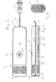
- Each microphone contains in a housing 21, cf. FIGS. 2-4, a customary microphone capsule 22, a preamplifier 23 for the microphone signals and control electronics 25 indicated by the switch symbol.
- a pushbutton switch 24 which can be actuated by the discussion participants is provided on the housing.
- the microphone signals from the preamplifier 23 pass through two speech wires of the common cable 3 to the amplifier device 11 in the control center 1 when the control electronics 25 have switched on the microphone 2 in question due to corresponding control signals from the computer 12 in the control center 1.
- the respective operating state of the microphone is indicated by an LED 26, cf. Figure 4, which lights up when the microphone is switched on.
- the control electronics 25 of each microphone are individually coded according to a one-time manual setting for a specific address.
- the control electronics receives all control signals from the computer 12, but responds to a control signal only if it has the address corresponding to the respective coding contains.
- the control electronics 25 also generates signal signals in accordance with the actuation of the pushbutton switch 24, which likewise carry an address corresponding to the respective coding of the control electronics 25.
- the message signals go via the cable 3 to the computer 12 and are processed there depending on the respective program of the computer, for example in such a way that the computer 12 immediately switches on the microphone 2 by means of suitable control signals, in which the key switch 4 was actuated, and all other microphones turns off, or in such a way that the computer 12 sets the microphone 2, in which a key switch 4 has been actuated, to a stored message list and only switches on when the computer in the course of processing the message list at the microphone in question has arrived.
- FIG. 2 to 4 show further structural details of one of the same microphones 2.
- the housing 21 of the microphone 2 has the shape of a rectangular cylinder with rounded longitudinal edges.
- the microphone capsule 22 is arranged on one end 31 of the housing, which is on the left in FIG.
- the LED 26 is provided in the end wall or the speaking screen 31.
- the flexible connecting cable 27, which ends at the plug 28, emerges from the opposite end 32.
- the key switch 24 is installed in the large side wall 33 of the housing 21 shown in FIG. 2.
- the LED 26 could also be provided in this upper side wall 33, for example in structural association with the pushbutton switch.
- a circuit board 29 extends between the two ends 31 and 32, which both in conventional technology contains the preamplifier 3 and the control electronics 25.
- Preamplifier and control electronics are thus integrated into the microphone 2; Via the connecting cable 7 and the plug 28 which can be inserted into one of the microphone sockets 4, a direct galvanic connection to the cable 3 is thus made without the insertion of further electrical modules.
- the housing 21 can e.g. be designed as a double-shell plastic housing.
- a number of microphones 2 corresponding to the number of discussion participants present, where the discussion participants are sitting, is connected by means of the plug 28 to the permanently installed microphone sockets 4.
- the remaining microphone sockets 4 in the room remain unoccupied.
- the operator of the conference room only has a comparatively small number of microphones 2. He rents additional microphones 2 for large events.
- two discussion participants share a microphone. Both of them can comfortably take the microphone 2 due to its design as a hand microphone with a longer, flexible connecting cable 27 and use it without having to bend over to the microphone or even have to go to the microphone.
Landscapes
- Physics & Mathematics (AREA)
- Engineering & Computer Science (AREA)
- Acoustics & Sound (AREA)
- Signal Processing (AREA)
- Circuit For Audible Band Transducer (AREA)
- Selective Calling Equipment (AREA)
- Details Of Audible-Bandwidth Transducers (AREA)
Priority Applications (1)
| Application Number | Priority Date | Filing Date | Title |
|---|---|---|---|
| AT86101833T ATE52373T1 (de) | 1985-02-15 | 1986-02-13 | Rechnergesteuerte elektroakustische diskussionsanlage. |
Applications Claiming Priority (2)
| Application Number | Priority Date | Filing Date | Title |
|---|---|---|---|
| DE19853505348 DE3505348A1 (de) | 1985-02-15 | 1985-02-15 | Rechnergesteuerte elektroakustische diskussionsanlage |
| DE3505348 | 1985-02-15 |
Publications (3)
| Publication Number | Publication Date |
|---|---|
| EP0191492A2 true EP0191492A2 (fr) | 1986-08-20 |
| EP0191492A3 EP0191492A3 (en) | 1987-12-16 |
| EP0191492B1 EP0191492B1 (fr) | 1990-04-25 |
Family
ID=6262684
Family Applications (1)
| Application Number | Title | Priority Date | Filing Date |
|---|---|---|---|
| EP86101833A Expired - Lifetime EP0191492B1 (fr) | 1985-02-15 | 1986-02-13 | Dispositif de discussion contrôlé par ordinateur |
Country Status (3)
| Country | Link |
|---|---|
| EP (1) | EP0191492B1 (fr) |
| AT (1) | ATE52373T1 (fr) |
| DE (2) | DE3505348A1 (fr) |
Cited By (2)
| Publication number | Priority date | Publication date | Assignee | Title |
|---|---|---|---|---|
| EP0566194A2 (fr) * | 1992-04-16 | 1993-10-20 | Koninklijke Philips Electronics N.V. | Système de conférence muni d'une reconnaissance automatique du locuteur et unité de locuteur destiné à être utilisé dans ce système de conférence |
| DE102004033866A1 (de) * | 2004-07-13 | 2006-02-16 | Fraunhofer-Gesellschaft zur Förderung der angewandten Forschung e.V. | Konferenz-Endgerät mit Echoreduktion für ein Sprachkonferenzsystem |
Family Cites Families (5)
| Publication number | Priority date | Publication date | Assignee | Title |
|---|---|---|---|---|
| US3626097A (en) * | 1969-09-26 | 1971-12-07 | Audio Designs & Mfg | Accessing controller for multiple-input plural output signal control console device |
| DE2321898C3 (de) * | 1973-04-30 | 1975-10-23 | Siemens Ag, 1000 Berlin Und 8000 Muenchen | Elektroakustische Anlage mit mehreren räumlich verteilten Mikrofonen |
| DE2523864A1 (de) * | 1975-05-30 | 1976-12-16 | Heinrich Peiker | Mikrofon-lautsprecherkombination fuer kommunikationssysteme |
| US4281314A (en) * | 1978-06-05 | 1981-07-28 | Morris S. Wagner | Selection switching apparatus |
| GB2123193B (en) * | 1982-06-19 | 1985-12-11 | James Ernest Gleave | Public address system |
-
1985
- 1985-02-15 DE DE19853505348 patent/DE3505348A1/de not_active Withdrawn
-
1986
- 1986-02-13 AT AT86101833T patent/ATE52373T1/de active
- 1986-02-13 EP EP86101833A patent/EP0191492B1/fr not_active Expired - Lifetime
- 1986-02-13 DE DE8686101833T patent/DE3670747D1/de not_active Expired - Lifetime
Cited By (5)
| Publication number | Priority date | Publication date | Assignee | Title |
|---|---|---|---|---|
| EP0566194A2 (fr) * | 1992-04-16 | 1993-10-20 | Koninklijke Philips Electronics N.V. | Système de conférence muni d'une reconnaissance automatique du locuteur et unité de locuteur destiné à être utilisé dans ce système de conférence |
| US5404397A (en) * | 1992-04-16 | 1995-04-04 | U.S. Phillips Corporation | Conference system with automatic speaker detection and speaker unit |
| DE102004033866A1 (de) * | 2004-07-13 | 2006-02-16 | Fraunhofer-Gesellschaft zur Förderung der angewandten Forschung e.V. | Konferenz-Endgerät mit Echoreduktion für ein Sprachkonferenzsystem |
| DE102004033866B4 (de) * | 2004-07-13 | 2006-11-16 | Fraunhofer-Gesellschaft zur Förderung der angewandten Forschung e.V. | Konferenz-Endgerät mit Echoreduktion für ein Sprachkonferenzsystem |
| US7853007B2 (en) | 2004-07-13 | 2010-12-14 | Fraunhofer-Gesellschaft Zur Foerderung Der Angewandten Forschung E.V. | Conference terminal with echo reduction for a voice conference system |
Also Published As
| Publication number | Publication date |
|---|---|
| EP0191492B1 (fr) | 1990-04-25 |
| DE3670747D1 (de) | 1990-05-31 |
| ATE52373T1 (de) | 1990-05-15 |
| DE3505348A1 (de) | 1986-08-21 |
| EP0191492A3 (en) | 1987-12-16 |
Similar Documents
| Publication | Publication Date | Title |
|---|---|---|
| EP0557847A1 (fr) | Appareils portatif à tête pour sourds | |
| EP0941014A2 (fr) | Système d'appareil auditif avec deux prothèses auditives et méthode de fonctionnement d'un tel système auditif | |
| EP0191492B1 (fr) | Dispositif de discussion contrôlé par ordinateur | |
| DE19702562B4 (de) | Steuerkarte zum Fernschalten von Geräten/Anlagen über das Telefonnetz | |
| DE2523864A1 (de) | Mikrofon-lautsprecherkombination fuer kommunikationssysteme | |
| DE8504347U1 (de) | Rechnergesteuerte elektroakustische Diskussionsanlage | |
| EP3490274B1 (fr) | Poste téléphonique pour un réseau d'intercommunication | |
| DE3412418C2 (fr) | ||
| DE2547188A1 (de) | Kombinierte ruf-, tuersprech- und -oeffneranlage | |
| DE2265451C2 (de) | Drahtfunksystem mit Fernsprechdienst | |
| DE202008003377U1 (de) | Vorrichtung für Konferenztische o.dgl. | |
| DE4217648A1 (de) | Bett-Bediengerät mit zusätzlichen Funktionen | |
| DE19521124C1 (de) | Anschlußelelement für Lautsprecher-Boxen | |
| DE2019899C3 (de) | Kombinierte Ruf-, Türsprech- und Öffner anlage | |
| DE972766C (de) | Sprechanlage mit mehreren Stationen und zentralem Verstaerker | |
| DE1177689B (de) | Schaltungsanordnung fuer kombinierte Tuersprech- und -oeffneranlagen in Mehrwohnungshaeusern | |
| DE3308986A1 (de) | Schaltungsanordnung fuer eine digitale fernsprechstation | |
| DE3424122C1 (de) | Schaltungsanordnung für ein Nebenuhrnetz | |
| DE2621933A1 (de) | Sprachlehranlage | |
| DE3705562A1 (de) | Telekommunikations-anschluss-einheit | |
| DE104080C (fr) | ||
| EP1122935A2 (fr) | Autocommutateur privé commandé par ordinateur | |
| DE1132979B (de) | Lichtruf- und Sprechanlage fuer Krankenhaeuser | |
| EP0658033A2 (fr) | Autocommutateur privé | |
| DE19949657A1 (de) | Wandleiste zum Anbringen an einer Zimmerwand und Multimediasystem mit einer solchen Wandleiste |
Legal Events
| Date | Code | Title | Description |
|---|---|---|---|
| PUAI | Public reference made under article 153(3) epc to a published international application that has entered the european phase |
Free format text: ORIGINAL CODE: 0009012 |
|
| AK | Designated contracting states |
Kind code of ref document: A2 Designated state(s): AT BE CH DE FR GB IT LI LU NL SE |
|
| PUAL | Search report despatched |
Free format text: ORIGINAL CODE: 0009013 |
|
| AK | Designated contracting states |
Kind code of ref document: A3 Designated state(s): AT BE CH DE FR GB IT LI LU NL SE |
|
| 17P | Request for examination filed |
Effective date: 19880616 |
|
| 17Q | First examination report despatched |
Effective date: 19881006 |
|
| GRAA | (expected) grant |
Free format text: ORIGINAL CODE: 0009210 |
|
| AK | Designated contracting states |
Kind code of ref document: B1 Designated state(s): AT BE CH DE FR GB IT LI LU NL SE |
|
| PG25 | Lapsed in a contracting state [announced via postgrant information from national office to epo] |
Ref country code: IT Free format text: LAPSE BECAUSE OF FAILURE TO SUBMIT A TRANSLATION OF THE DESCRIPTION OR TO PAY THE FEE WITHIN THE PRESCRIBED TIME-LIMIT;WARNING: LAPSES OF ITALIAN PATENTS WITH EFFECTIVE DATE BEFORE 2007 MAY HAVE OCCURRED AT ANY TIME BEFORE 2007. THE CORRECT EFFECTIVE DATE MAY BE DIFFERENT FROM THE ONE RECORDED. Effective date: 19900425 Ref country code: SE Effective date: 19900425 Ref country code: BE Effective date: 19900425 Ref country code: NL Effective date: 19900425 |
|
| REF | Corresponds to: |
Ref document number: 52373 Country of ref document: AT Date of ref document: 19900515 Kind code of ref document: T |
|
| REF | Corresponds to: |
Ref document number: 3670747 Country of ref document: DE Date of ref document: 19900531 |
|
| ET | Fr: translation filed | ||
| GBT | Gb: translation of ep patent filed (gb section 77(6)(a)/1977) | ||
| NLV1 | Nl: lapsed or annulled due to failure to fulfill the requirements of art. 29p and 29m of the patents act | ||
| PG25 | Lapsed in a contracting state [announced via postgrant information from national office to epo] |
Ref country code: AT Effective date: 19910213 |
|
| PLBE | No opposition filed within time limit |
Free format text: ORIGINAL CODE: 0009261 |
|
| STAA | Information on the status of an ep patent application or granted ep patent |
Free format text: STATUS: NO OPPOSITION FILED WITHIN TIME LIMIT |
|
| PG25 | Lapsed in a contracting state [announced via postgrant information from national office to epo] |
Ref country code: CH Effective date: 19910228 Ref country code: LU Free format text: LAPSE BECAUSE OF NON-PAYMENT OF DUE FEES Effective date: 19910228 Ref country code: LI Effective date: 19910228 |
|
| 26N | No opposition filed | ||
| PG25 | Lapsed in a contracting state [announced via postgrant information from national office to epo] |
Ref country code: FR Effective date: 19911031 |
|
| REG | Reference to a national code |
Ref country code: CH Ref legal event code: PL |
|
| REG | Reference to a national code |
Ref country code: FR Ref legal event code: ST |
|
| PGFP | Annual fee paid to national office [announced via postgrant information from national office to epo] |
Ref country code: GB Payment date: 20010226 Year of fee payment: 16 |
|
| REG | Reference to a national code |
Ref country code: GB Ref legal event code: IF02 |
|
| PG25 | Lapsed in a contracting state [announced via postgrant information from national office to epo] |
Ref country code: GB Free format text: LAPSE BECAUSE OF NON-PAYMENT OF DUE FEES Effective date: 20020213 |
|
| GBPC | Gb: european patent ceased through non-payment of renewal fee |
Effective date: 20020213 |
|
| PGFP | Annual fee paid to national office [announced via postgrant information from national office to epo] |
Ref country code: DE Payment date: 20050225 Year of fee payment: 20 |