EP0191560A2 - Drehmomentüberwachungsvorrichtung - Google Patents
Drehmomentüberwachungsvorrichtung Download PDFInfo
- Publication number
- EP0191560A2 EP0191560A2 EP86300402A EP86300402A EP0191560A2 EP 0191560 A2 EP0191560 A2 EP 0191560A2 EP 86300402 A EP86300402 A EP 86300402A EP 86300402 A EP86300402 A EP 86300402A EP 0191560 A2 EP0191560 A2 EP 0191560A2
- Authority
- EP
- European Patent Office
- Prior art keywords
- sensor
- assembly
- clutch
- parts
- monitoring
- Prior art date
- Legal status (The legal status is an assumption and is not a legal conclusion. Google has not performed a legal analysis and makes no representation as to the accuracy of the status listed.)
- Withdrawn
Links
Images

Classifications
-
- G—PHYSICS
- G01—MEASURING; TESTING
- G01L—MEASURING FORCE, STRESS, TORQUE, WORK, MECHANICAL POWER, MECHANICAL EFFICIENCY, OR FLUID PRESSURE
- G01L3/00—Measuring torque, work, mechanical power, or mechanical efficiency, in general
-
- G—PHYSICS
- G01—MEASURING; TESTING
- G01L—MEASURING FORCE, STRESS, TORQUE, WORK, MECHANICAL POWER, MECHANICAL EFFICIENCY, OR FLUID PRESSURE
- G01L3/00—Measuring torque, work, mechanical power, or mechanical efficiency, in general
- G01L3/02—Rotary-transmission dynamometers
- G01L3/14—Rotary-transmission dynamometers wherein the torque-transmitting element is other than a torsionally-flexible shaft
- G01L3/1407—Rotary-transmission dynamometers wherein the torque-transmitting element is other than a torsionally-flexible shaft involving springs
- G01L3/1428—Rotary-transmission dynamometers wherein the torque-transmitting element is other than a torsionally-flexible shaft involving springs using electrical transducers
- G01L3/1435—Rotary-transmission dynamometers wherein the torque-transmitting element is other than a torsionally-flexible shaft involving springs using electrical transducers involving magnetic or electromagnetic means
-
- F—MECHANICAL ENGINEERING; LIGHTING; HEATING; WEAPONS; BLASTING
- F16—ENGINEERING ELEMENTS AND UNITS; GENERAL MEASURES FOR PRODUCING AND MAINTAINING EFFECTIVE FUNCTIONING OF MACHINES OR INSTALLATIONS; THERMAL INSULATION IN GENERAL
- F16H—GEARING
- F16H59/00—Control inputs to control units of change-speed- or reversing-gearings for conveying rotary motion
- F16H59/14—Inputs being a function of torque or torque demand
- F16H59/16—Dynamometric measurement of torque
Definitions
- This invention relates to a method of monitoring torque in a drive transmission incorporating a friction clutch having damper springs, and further relates to a friction clutch for use in such monitoring, and a torque monitoring system utilizing the clutch.
- a method of monitoring torque in the transmission comprises monitoring the extent of the relative movement of said two parts of said drive transmitting member.
- the relative movement of said parts is monitored remotely by sensor means relative to which said two part member rotates.
- a friction clutch assembly having a two part, rotatable, drive transmitting member, the two parts of said member being movable relative to one another against the action of damper spring means, the clutch further including a plurality of angularly spaced reference means on each of said parts of said two part member respectively and sensor means relative to which said two parts member rotates, said sensor means monitoring said reference means and in use producing, at a plurality of points in each revolution of the two part member, an output representative of the relative positions of said parts of said two part member.
- the angular spacing of said reference means within each plurality of reference means is a generally equiangular spacing
- said plurality reference means comprises a first plurality of elements carried by one part of said two part member and generally equiangularly spaced around the axis of rotation of said two part member, and, a second equal plurality of elements carried by the other part of said two part member and generally equiangularly spaced around the axis of rotation of said two part member, the elements of said first plurality and the elements of said second plurality being so positioned on their respective parts that their orbits of movement are close to one another.
- said elements of said first plurality are interdigitated with the elements of said second plurality.
- a second sensor also monitoring said reference means and in use producing an output representative of the relative positions of said parts of said two part member, said second sensor being angularly spaced about the axis of rotation of said member from the first sensor so as to produce an output between successive outputs of the first sensor.
- said second sensor is spaced angularly from said first sensor by an angular distance equal to half of the angular distance between adjacent reference means of said first plurality of reference means or by an odd number multiple thereof.
- the assembly may be provided with a third or more further sensor.
- means for producing a datum signal at the same point in each revolution of the first part of said two part member Preferably there is provided means for producing a datum signal at the same point in each revolution of the first part of said two part member.
- said means comprises a further sensor and a datum means rotatable with said two part member adjacent said further sensor.
- said means comprises a sensor monitoring said reference means and a selected one of said reference means which has been arranged to cause the sensor to produce an output which is distinct from the output produced by the other reference means.
- the clutch is a diaphragm clutch and said sensor or sensors monitoring said reference means are carried by the stationary clutch release bearing guide sleeve of the clutch, said sensor or sensors being positioned between the inner face of the diaphragm spring and the driven plate of the clutch.
- the invention further resides in a torque monitoring system comprising a friction clutch as specified above and an associated microprocessor for processing the output of the or each sensor.
- Figures 5, 6, 7 and 8 are graphical representation of the operation of monitoring torque in the assembly illustrated in Figures 1 to 4 and modifications thereof
- Figure 9 is a diagrammatic representation of a modified arrangement
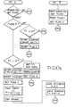
- Figure 10 is a flow diagram related to the arrangment of Figure 9.
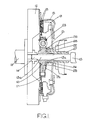
- the clutch which is illustrated is a dry plate friction clutch of the kind known as a diaphragm clutch and its construction and operation as a clutch will be well understood by those familiar with clutches.
- the clutch is interposed in the drive transmission system between the engine and the gear-box and is operable, when engaged, to transmit drive from the engine to the gear-box, and is operable when disengaged, to disconnect the engine from the gear- box.
- the engine and gear-box can be of completely conventional form, the output from the engine being by way of the engine crank-shaft 11, and the fly-wheel 12 which rotates with the crank-shaft 11 being secured thereto.
- Drive is transmitted into the gear-box by a shaft 13 one end 14 of which is journalled for rotation in, and co-axial with, the fly-wheel 12.
- the driven plate of the clutch further includes an annular component 17 mounted on the hub 16 for limited rotational movement about the axis of the hub 16.
- the component 17 carries at its periphery, oppositely presented annular friction members 18.
- An annular pressure plate 19 is normally urged by a diaphragm spring 21 towards the fly-wheel 12 thus trapping the friction members 18 between the face of the fly-wheel and a mutually presented face of the pressure plate 19.
- the clutch can be released by movement of a release bearing 22 axially towards the fly-wheel along the shaft 13, the release bearing 22 flexing the diaphragm spring 21 to release the pressure plate 19 and thus permit the pressure plate 19 and fly-wheel 12 to rotate relative to the friction members 18.
- the construction of the driven plate is generally conventional in that the limited rotational movement of the annular member 17 on the hub 16 is opposed, irrespective of the direction of the relative rotational movement, by four equiangularly spaced circumferentially extending damper springs 23. It is usual for one pair, generally a diametrically opposed pair, of damper springs to be more highly rated than the other pair thereby providing a "knee-type" characteristic. As is well understood the damper springs 23 are provided in order to permit limited relative rotation between the annular component 17 and the hub 16 thereby minimising transmission of snatch and shock loadings through the clutch. It will be appreciated that the proportionality between the torque and damper spring movement is retained over the full clutch characteristic. However, the constant of proportionality will depend upon which side of the "knee" of the characteristic the clutch is operating.
- the inventors have recognised that the torque transmitted by the driven plate of the clutch can be monitored by monitoring the relative positions of the annular component 17 and the hub 16.
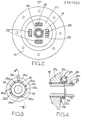
- a plate 17a of the annular component 17 at the face of the driven plate remote from the fly-wheel 12 are both provided with toothed rings 24, and 25 respectively.
- the rings 24, 25 have their axes coincident with the axis of the hub, and each ring carries four equiangularly spaced teeth indicated in the drawings by the suffix a (best seen in Figure 3).
- the teeth 24a of the ring 24 extend radially outwardly from the ring whereas the teeth 25a of the ring 25 extend axially.
- the axially extending teeth 25a pass between the radially extending teeth 24a and thus although the rings 24, 25 are axially spaced by a small distance their teeth are "interdigitated" and can share a common path of revolution as the driven plate of the clutch rotates.
- a sensor 26 In order to monitor the relative positions of the teeth 24a, 25a there is provided a sensor 26.
- the aforementioned clutch release bearing 22 which is slidable axially relative to the shaft 13 is slidable on a stationary clutch release bearing guide sleeve 27 through which the shaft 13 extends.
- the sleeve 27 is provided with an extension 28 upon which the sensor 26 is mounted.
- the sensor 26 is position radially outwardly from, and axially aligned with, the teeth 24a, 25a and since the sleeve 27 is stationary the making of electrical connections to the sensor 26 is a relatively simple matter.
- the teeth 24a, 25a constitute reference points to be monitored by a sensor. It is preferred that the rings 24, 25 and their respective teeth are ferromagnetic and that the sensor 26 is a variable reluctance sensor. It is to be understood however that other monitoring arrangements could be provided, for example the sensor could be an optical sensor monitoring reference marks on the hub 16 and components 17. Such an arrangement might however prove disadvantageous in view of the relatively dirty environment.
- the extent of the relative angular movement of the teeth 24a, 25a is directly proportional to the torque being transmitted by the driven plate of the clutch and since there are four pairs of teeth the torque can be monitored four times during each revolution of the driven plate.
- the passage of the teeth across the face of the sensor 26 generates a train of electrical pulses which can be processed by relatively simple circuitry to produce a square wave-form the mark/space ratio of which at any given instant will be proportional to the torque being transmitted at that instant.
- the mark/space ratio of the wave-form will vary in proportion to the applied torque.
- the information, conveyed by the wave-form can be applied together with other engine and transmission control parameters to, for example, a self adaptive engine management system or to an electronically controlled transmission system.
- each tooth beneath the sensor may produce a pulse of the same magnitude, or alternatively the teeth can be arranged so that the teeth 24a of the hub 16, which can be considered to be fixed teeth, produce a pulse of greater amplitude than the teeth 25a, which can be considered to be movable teeth, that is to say teeth which are movable relative to the fixed teeth 24a.
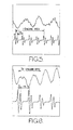
- Figure 5 shows, in its upper and lower curves, the variation of different parameters in the same period of operation of an in-line four cylinder, four stroke internal combustion engine having a torque monitoring arrangement as illustrated in Figures 1 to 4.
- the upper curve illustrates torque fluctuations occuring in approximately 1.5 revolutions
- the lower curve represents the pulse train, during the equivalent time period, issuing from the sensor 26.
- the period of one engine revolution is indicated in Figure 5, and it will be understood that during each engine revolution two of the four cylinders will fire.
- the train of pulses includes a large amplitude pulse representative of a fixed tooth passing the sensor and followed by a pulse of lower amplitude presenting a movable tooth passing the sensor.
- Figure 6 is similar to Figure 5 except that it is of an enlarged scale, and it can be seen that in Figure 6 the period of 0.5 an engine revolution occupies almost as much width as a complete engine revolution in Figure 5.
- Figure 6 illustrates a problem which can be encountered with the relatively simple torque monitoring arrangement described above in relation to Figures 1 to 5. It is found that when the engine is running at substantially constant speed the engine can become synchronized with a resonance at twice the firing frequency, and the resultant torque cycle wave-form can achieve a constant phase relationship with rotation of the crank-shaft such that the passage of each fixed tooth beneath the sensor 26 corresponds to the same point in the repeating torque cycle.
- an anomalous indication of the torque can be produced since it may be that the torque is monitored by each pair of fixed movable teeth at, for example, the point in the torque cycle at which the torque is at a maximum, or equally at a point in the cycle at which the torque is at a minimum.
- the computed average would, in these two cases, be totally unrealistic since in one case the computed average would equal the maximum torque occuring at any point in the cycle, and in the other case the computed average would equal the minimum torque which occurs at any point in the cycle.
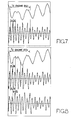
- Figure 7 is a view similar to Figure 6 but shows a pulse train derived from a sensor 26 monitoring eight, rather than, four pairs of fixed and movable teeth.
- the pulses produced by the teeth passing the sensor are not instantaneous, and have a finite time period between growth from zero to maximum amplitude, and then decay through zero to minimum amplitude. If the teeth are crowded too closely together then there is a danager that the leading edge of a subsequent pulse will interfere with the trailing edge of the previous pulse and the sensor will not be able to discriminate between the adjacent teeth. As will be mentioned later it is desirable to arrange the associated electronics to react to the zero crossing points of the pulses and not to the peaks.
- Figure 8 is a view similar to Figure 7, but illustrating an arrangement having eight pairs of fixed and movable teeth (as in Figure 7) and also utilizing a second sensor (the lower of the three curves in Figure 8).
- the angular spacing of the second sensor from the first sensor around the axis of rotation of the teeth is determined by the angular spacing between adjacent fixed teeth.
- the second sensor will thus be spaced from the first sensor by 45°(or 3 x 45°, 5 x 45° etc) so that a fixed tooth passes the second sensor when the first sensor lies half way between adjacent fixed teeth.
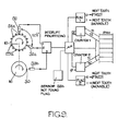
- Figure 9 there is illustrated an arrangement utilizing eight pairs of teeth and in such an arrangement the second sensor will be spaced from the first sensor by 22 1 / 2 ° (or 3 x 22 1 / 2 °, or 5 x 22 1 / 2 °, or 7 x 22 1 / 2 °).
- FIG. 9 illustrates, in addition to the second sensor 26a, a third sensor 26b.
- the sensor 26b is associated with a single tooth 30 rotating with the crank shaft of the engine.
- FIG. 9 The right hand side of Figure 9, and the flow diagram of Figure 10 illustrate in general terms one example of a microprocessor arrangement for interpreting the pulse trains produced by the three sensors 26, 26a, 26b it being understood that in a practical arrangment it is probable that the result obtained from the sensor 26b in association with the tooth 30 will actually be obtained from the sensor 26 and an appropriately modified tooth 24a.
- T1 relates to the spacing of a fixed tooth pulse from the subsequent movable tooth pulse
- references to T2 relate to the spacing of the movable tooth pulse from the next fixed tooth pulse, as seen by the sensor 26.
- references to T'1 and T'2 relate to the pulse spacing as seen by the sensor 26a. It will be noted that the spacings T1 and T2 are illustrated in Figures 5, 6, 7 and 8, and additionally Figure 8 also illustrates the spacing T'-I, T'2.
- the tooth 30 and its associated sensor 26b ensure that the counting of pulses which is performed by the microprocessor, commences with the pulse generated by a fixed, rather than a movable tooth.
- a still further benefit of establishing the datum is that it enables the system to be set-up to accommodate any manufacturing tolerances which may occur in the spacing of the fixed teeth and/or the spacing of the movable teeth.
- the movable teeth and sensors will be such that the zero crossing points of the pulses produced by the fixed teeth are accurately equiangularly spaced and similarly that in a zero torque condition the pulses of the movable teeth would be equiangularly spaced. In practice this may not be the case, and it may for example be that owing to the manufacturing tolerances the zero crossing points of the pulses are not truely equiangularly spaced. However, once the teeth have been installed in the clutch the basic relationship between the zero crossing points of the pulses produced by the teeth will remain constant even if that relationship is not an equiangular spacing.
- the datum can be related to the actual tooth positions (at zero torque) and the programming of the microprocessor can be chosen to accommodate the actual angular relationship of the zero crossing points of the pulses produced by the teeth.
- each individual system can be set-up at the outset to accommodate the actual angular relationship which exists between the fixed teeth and between the movable teeth, and ultimately therefore a more accurate torque average can be calculated.
- teeth 24a, 25a and sensor 26 or sensors can be accommodated within the clutch with minimal changes to existing clutch design and construction.
Landscapes
- Physics & Mathematics (AREA)
- General Physics & Mathematics (AREA)
- Electromagnetism (AREA)
- Mechanical Operated Clutches (AREA)
- Force Measurement Appropriate To Specific Purposes (AREA)
Applications Claiming Priority (2)
| Application Number | Priority Date | Filing Date | Title |
|---|---|---|---|
| GB8502695 | 1985-02-02 | ||
| GB858502695A GB8502695D0 (en) | 1985-02-02 | 1985-02-02 | Torque monitoring |
Publications (2)
| Publication Number | Publication Date |
|---|---|
| EP0191560A2 true EP0191560A2 (de) | 1986-08-20 |
| EP0191560A3 EP0191560A3 (de) | 1987-08-26 |
Family
ID=10573853
Family Applications (1)
| Application Number | Title | Priority Date | Filing Date |
|---|---|---|---|
| EP86300402A Withdrawn EP0191560A3 (de) | 1985-02-02 | 1986-01-21 | Drehmomentüberwachungsvorrichtung |
Country Status (6)
| Country | Link |
|---|---|
| US (1) | US4683746A (de) |
| EP (1) | EP0191560A3 (de) |
| JP (1) | JPS61182546A (de) |
| KR (1) | KR900002113B1 (de) |
| BR (1) | BR8600406A (de) |
| GB (1) | GB8502695D0 (de) |
Cited By (8)
| Publication number | Priority date | Publication date | Assignee | Title |
|---|---|---|---|---|
| EP0478529A3 (en) * | 1990-09-25 | 1993-03-03 | Dr. Ing. Geislinger & Co. Schwingungstechnik Gesellschaft M.B.H. | Arrangement for the control of condition parameters of a drive determined by torsional vibrations |
| FR2686975A1 (fr) * | 1992-01-30 | 1993-08-06 | Fichtel & Sachs Ag | Dispositif destine a mesurer le couple de rotation transmis par un embrayage a friction. |
| DE19529462A1 (de) * | 1995-08-10 | 1997-02-13 | Iav Gmbh | Einrichtung zur Drehmomentermittlung für eine Antriebseinheit mit einem Verbrennungsmotor |
| EP0741286A3 (de) * | 1995-05-02 | 1997-05-02 | New Holland Italia Spa | Messung der Rotationsgeschwindigkeit und des Drehmomentes |
| DE19717290A1 (de) * | 1997-04-24 | 1998-10-29 | Claas Usines France | Vorrichtung zur Drehmomentmessung |
| DE19730398A1 (de) * | 1997-07-16 | 1998-11-26 | Daimler Benz Ag | Vorrichtung zur Drehmomentbestimmung in einem Motorantriebsstrang |
| CN1865891B (zh) * | 2005-05-17 | 2011-11-09 | 艾勒根驱动工程有限责任公司 | 用于监测扭转振动减振器的方法 |
| CN105588716A (zh) * | 2015-12-15 | 2016-05-18 | 浙江理工大学 | 一种从动盘总成扭转检测疲劳试验机 |
Families Citing this family (13)
| Publication number | Priority date | Publication date | Assignee | Title |
|---|---|---|---|---|
| DE3619408A1 (de) * | 1986-06-09 | 1987-12-10 | Battelle Institut E V | Anordnung zur gewinnung von geradsymmetrischen signalen |
| US4823552A (en) * | 1987-04-29 | 1989-04-25 | Vickers, Incorporated | Failsafe electrohydraulic control system for variable displacement pump |
| DE3810194C1 (de) * | 1988-03-25 | 1989-08-24 | Daimler-Benz Aktiengesellschaft, 7000 Stuttgart, De | |
| US4979398A (en) * | 1989-09-28 | 1990-12-25 | Allied-Signal Inc. | Torque measurement circuit |
| US5207092A (en) * | 1991-04-10 | 1993-05-04 | Dana Corporation | Apparatus for spin checking clutch driven disc assemblies |
| US6085600A (en) * | 1995-07-17 | 2000-07-11 | Meritor Light Vehicle Systems | Torque measuring device for window regulator |
| KR100283294B1 (ko) * | 1998-05-13 | 2001-03-02 | 장태환 | 자동차엔진출력토오크의실시간측정장치 |
| DE10052069C2 (de) * | 2000-10-19 | 2002-11-14 | Walterscheid Gmbh Gkn | Vorrichtung zum Messen von Drehmomenten in einer Antriebsanordnung |
| DE10154737C1 (de) * | 2001-11-09 | 2003-04-24 | Walterscheid Gmbh Gkn | Vorrichtung zum Messen von Drehmomenten und der Drehrichtung in einer Antriebsanordnung |
| DE10229084A1 (de) * | 2002-06-28 | 2004-01-29 | Zf Sachs Ag | Reibungskupplung mit einer Drehmomenterfassungsanordnung und einer Verschleißerfassungsanordnung, Drehmomenterfassungsanordnung bzw. Verschleißerfassungsanordnung für eine Reibungskupplung |
| US9234815B2 (en) | 2011-09-01 | 2016-01-12 | Volvo Lastvagnar Ab | Torque measuring system and a method thereof |
| BR112014007875A2 (pt) | 2011-09-06 | 2017-06-20 | Volvo Lastvagnar Ab | uma disposição e um método para adaptação de um sistema de controle de cruzeiro em um veículo |
| ITMO20110297A1 (it) * | 2011-11-18 | 2013-05-19 | Cnh Italia Spa | Metodo per calibrare un rilevatore in un insieme smorzante. |
Family Cites Families (8)
| Publication number | Priority date | Publication date | Assignee | Title |
|---|---|---|---|---|
| GB605716A (en) * | 1946-05-30 | 1948-07-29 | Francis James Allen | Improvements in or relating to torque-measuring or indicating devices |
| DE955833C (de) * | 1952-12-25 | 1957-01-10 | Stromag Maschf | Vorrichtung zum Schalten von Reibungskupplungen unter Verwendung von mindestens zwei Magnet-Induktoren |
| DE1053794B (de) * | 1954-08-02 | 1959-03-26 | Daimler Benz Ag | Vorrichtung zum Messen der Relativbewegung von Reibscheibenkupplungen, insbesondere Kraftfahrzeugkupplungen |
| DE1405970A1 (de) * | 1962-03-23 | 1969-01-30 | Fichtel & Sachs Ag | Vorrichtung zur Drehmomentbegrenzung fuer durch Hilfskraft ausrueckbare Kupplungen,insbesondere fuer Kraftfahrzeuge |
| DE1773305A1 (de) * | 1968-04-27 | 1971-11-25 | Lohmann & Stolterfoht Ag | Verfahren zur Messung von Drehmomenten |
| DE2356745A1 (de) * | 1973-11-14 | 1975-05-15 | Artur Annuschies | Kupplungsanordnung |
| US4513626A (en) * | 1982-02-22 | 1985-04-30 | Nippon Soken, Inc. | Torque detector |
| US4488443A (en) * | 1983-01-20 | 1984-12-18 | Simmonds Precision Products, Inc. | Expanded range monopole torque measuring system |
-
1985
- 1985-02-02 GB GB858502695A patent/GB8502695D0/en active Pending
-
1986
- 1986-01-21 EP EP86300402A patent/EP0191560A3/de not_active Withdrawn
- 1986-01-22 US US06/821,392 patent/US4683746A/en not_active Expired - Fee Related
- 1986-01-31 BR BR8600406A patent/BR8600406A/pt unknown
- 1986-01-31 JP JP61018241A patent/JPS61182546A/ja active Pending
- 1986-02-01 KR KR1019860000688A patent/KR900002113B1/ko not_active Expired
Cited By (9)
| Publication number | Priority date | Publication date | Assignee | Title |
|---|---|---|---|---|
| EP0478529A3 (en) * | 1990-09-25 | 1993-03-03 | Dr. Ing. Geislinger & Co. Schwingungstechnik Gesellschaft M.B.H. | Arrangement for the control of condition parameters of a drive determined by torsional vibrations |
| FR2686975A1 (fr) * | 1992-01-30 | 1993-08-06 | Fichtel & Sachs Ag | Dispositif destine a mesurer le couple de rotation transmis par un embrayage a friction. |
| EP0741286A3 (de) * | 1995-05-02 | 1997-05-02 | New Holland Italia Spa | Messung der Rotationsgeschwindigkeit und des Drehmomentes |
| DE19529462A1 (de) * | 1995-08-10 | 1997-02-13 | Iav Gmbh | Einrichtung zur Drehmomentermittlung für eine Antriebseinheit mit einem Verbrennungsmotor |
| DE19529462B4 (de) * | 1995-08-10 | 2004-09-02 | Iav Gmbh Ingenieurgesellschaft Auto Und Verkehr | Einrichtung zur Drehmomentermittlung für eine Antriebseinheit mit einem Verbrennungsmotor |
| DE19717290A1 (de) * | 1997-04-24 | 1998-10-29 | Claas Usines France | Vorrichtung zur Drehmomentmessung |
| DE19730398A1 (de) * | 1997-07-16 | 1998-11-26 | Daimler Benz Ag | Vorrichtung zur Drehmomentbestimmung in einem Motorantriebsstrang |
| CN1865891B (zh) * | 2005-05-17 | 2011-11-09 | 艾勒根驱动工程有限责任公司 | 用于监测扭转振动减振器的方法 |
| CN105588716A (zh) * | 2015-12-15 | 2016-05-18 | 浙江理工大学 | 一种从动盘总成扭转检测疲劳试验机 |
Also Published As
| Publication number | Publication date |
|---|---|
| KR860006694A (ko) | 1986-09-13 |
| BR8600406A (pt) | 1986-10-14 |
| GB8502695D0 (en) | 1985-03-06 |
| EP0191560A3 (de) | 1987-08-26 |
| JPS61182546A (ja) | 1986-08-15 |
| KR900002113B1 (ko) | 1990-04-02 |
| US4683746A (en) | 1987-08-04 |
Similar Documents
| Publication | Publication Date | Title |
|---|---|---|
| US4683746A (en) | Torque monitoring | |
| US8464598B2 (en) | Device for measuring the torque transmitted by a power shaft | |
| FI82555C (fi) | Foerfarande foer observering av operationen hos ett cykliskt roerligt, kraftalstrande eller kraftoeverfoerande element och anordning foer observering av operationen hos ett dylikt element. | |
| EP1208348B1 (de) | Linearer und rotierender magnetischer sensor | |
| US4135390A (en) | Engine torque transducer using a spoked torque transmitting plate | |
| AT502432B1 (de) | Verfahren zum überprüfen eines drehschwingungsdämpfers | |
| FR2428844A1 (fr) | Systeme pour mesurer la vitesse de rotation d'un organe tournant | |
| US6505504B1 (en) | Method and device for a real time measurement of output torque of an automobile engine | |
| US4774845A (en) | Method and device for measuring the torque transmitted by a shaft subjected to temperature variations | |
| US5675095A (en) | Rotational torque sensor | |
| US8892366B2 (en) | Method of measuring torque and torque measuring system for said method | |
| US4787255A (en) | Torquemeter | |
| US5247839A (en) | Torsion angle detection apparatus and torque sensor | |
| EP0531411A1 (de) | Laserdetektor. | |
| JP7380289B2 (ja) | トルク測定装置及びその製造方法 | |
| US20100282002A1 (en) | Measuring device for detecting the operating state of a shaft, method and shaft arrangement comprising said measuring device | |
| EP1124122A2 (de) | Kurbeltriebsensor | |
| CN113959722B (zh) | 基于音轮的扭矩-桨距-相角-转速集成测量装置及方法 | |
| US7415363B2 (en) | High resolution torque measurement on a rotating shaft with movement compensation | |
| JPH07505226A (ja) | 回転運動を伝達するためのギア伝動装置でトルクを測定するための装置 | |
| EP0205779B1 (de) | Messgeber, dem der Stand von mindestens einem mechanischen Drehelement zugrundeliegt | |
| SU1068816A1 (ru) | Датчик скорости вращени вала | |
| DE3231977C1 (de) | Anordnung zur Messung von relativen Drehwinkel-Schwankungen zwischen rotierenden Wellen | |
| GB2385425A (en) | A method of monitoring a load on a gearbox | |
| JPS59153137A (ja) | 機関トルク検出装置 |
Legal Events
| Date | Code | Title | Description |
|---|---|---|---|
| PUAI | Public reference made under article 153(3) epc to a published international application that has entered the european phase |
Free format text: ORIGINAL CODE: 0009012 |
|
| AK | Designated contracting states |
Kind code of ref document: A2 Designated state(s): DE FR GB IT |
|
| PUAL | Search report despatched |
Free format text: ORIGINAL CODE: 0009013 |
|
| AK | Designated contracting states |
Kind code of ref document: A3 Designated state(s): DE FR GB IT |
|
| RAP1 | Party data changed (applicant data changed or rights of an application transferred) |
Owner name: LUCAS INDUSTRIES PUBLIC LIMITED COMPANY |
|
| 17P | Request for examination filed |
Effective date: 19871120 |
|
| 17Q | First examination report despatched |
Effective date: 19900409 |
|
| STAA | Information on the status of an ep patent application or granted ep patent |
Free format text: STATUS: THE APPLICATION IS DEEMED TO BE WITHDRAWN |
|
| 18D | Application deemed to be withdrawn |
Effective date: 19900821 |
|
| RIN1 | Information on inventor provided before grant (corrected) |
Inventor name: FORRESTER, JOHN STUART Inventor name: SMITH, GERALD BARRINGTON Inventor name: CULLINGFORD, CHRISTOPHER VARNDELL |