EP0191638A2 - Appareil et méthode pour commander un essuie-glace - Google Patents
Appareil et méthode pour commander un essuie-glace Download PDFInfo
- Publication number
- EP0191638A2 EP0191638A2 EP86300974A EP86300974A EP0191638A2 EP 0191638 A2 EP0191638 A2 EP 0191638A2 EP 86300974 A EP86300974 A EP 86300974A EP 86300974 A EP86300974 A EP 86300974A EP 0191638 A2 EP0191638 A2 EP 0191638A2
- Authority
- EP
- European Patent Office
- Prior art keywords
- wiper
- output signal
- rain
- signal
- comparator
- Prior art date
- Legal status (The legal status is an assumption and is not a legal conclusion. Google has not performed a legal analysis and makes no representation as to the accuracy of the status listed.)
- Withdrawn
Links
Images




Classifications
-
- B—PERFORMING OPERATIONS; TRANSPORTING
- B60—VEHICLES IN GENERAL
- B60S—SERVICING, CLEANING, REPAIRING, SUPPORTING, LIFTING, OR MANOEUVRING OF VEHICLES, NOT OTHERWISE PROVIDED FOR
- B60S1/00—Cleaning of vehicles
- B60S1/02—Cleaning windscreens, windows or optical devices
- B60S1/04—Wipers or the like, e.g. scrapers
- B60S1/06—Wipers or the like, e.g. scrapers characterised by the drive
- B60S1/08—Wipers or the like, e.g. scrapers characterised by the drive electrically driven
- B60S1/0818—Wipers or the like, e.g. scrapers characterised by the drive electrically driven including control systems responsive to external conditions, e.g. by detection of moisture, dirt or the like
- B60S1/0822—Wipers or the like, e.g. scrapers characterised by the drive electrically driven including control systems responsive to external conditions, e.g. by detection of moisture, dirt or the like characterized by the arrangement or type of detection means
- B60S1/0825—Capacitive rain sensor
- B60S1/0829—Oscillator-resonator rain sensor
-
- B—PERFORMING OPERATIONS; TRANSPORTING
- B60—VEHICLES IN GENERAL
- B60S—SERVICING, CLEANING, REPAIRING, SUPPORTING, LIFTING, OR MANOEUVRING OF VEHICLES, NOT OTHERWISE PROVIDED FOR
- B60S1/00—Cleaning of vehicles
- B60S1/02—Cleaning windscreens, windows or optical devices
- B60S1/04—Wipers or the like, e.g. scrapers
- B60S1/06—Wipers or the like, e.g. scrapers characterised by the drive
- B60S1/08—Wipers or the like, e.g. scrapers characterised by the drive electrically driven
- B60S1/0818—Wipers or the like, e.g. scrapers characterised by the drive electrically driven including control systems responsive to external conditions, e.g. by detection of moisture, dirt or the like
-
- B—PERFORMING OPERATIONS; TRANSPORTING
- B60—VEHICLES IN GENERAL
- B60S—SERVICING, CLEANING, REPAIRING, SUPPORTING, LIFTING, OR MANOEUVRING OF VEHICLES, NOT OTHERWISE PROVIDED FOR
- B60S1/00—Cleaning of vehicles
- B60S1/02—Cleaning windscreens, windows or optical devices
- B60S1/04—Wipers or the like, e.g. scrapers
- B60S1/06—Wipers or the like, e.g. scrapers characterised by the drive
- B60S1/08—Wipers or the like, e.g. scrapers characterised by the drive electrically driven
- B60S1/0818—Wipers or the like, e.g. scrapers characterised by the drive electrically driven including control systems responsive to external conditions, e.g. by detection of moisture, dirt or the like
- B60S1/0822—Wipers or the like, e.g. scrapers characterised by the drive electrically driven including control systems responsive to external conditions, e.g. by detection of moisture, dirt or the like characterized by the arrangement or type of detection means
Definitions
- the present invention relates to an apparatus for controlling a wiper by controlling wiping speed of the wiper in accordance with an amount of rain. More particularly, the present invention relates to improvements in means for controlling the wiper which detects the amount of rain positioned on a detecting means regardless of the wiping speed of the wiper, so that even when the wiper moves at any wiping speed the apparatus according to the present invention can control the wiping speed of the wiper in accordance with the amount of rain positioned on the detecting means.
- a conventional wiper of an automobile moves at a low wiping speed or at a high wiping speed and the change of the wiping speeds is operated by manual operation.
- This apparatus includes detecting means for detecting an amount of rain positioned thereon and controlling means for controlling wiping speed of wiper.
- the detecting means is located on an exterior surface of a windshield of an automobile and the controlling means controls the wiping speed of the wiper in accordance with signal outputted from the detecting means.
- the detecting means outputs a continuous signal in accordance with the amount of rain positioned on the detecting means and the controlling means includes first and second comparator means which compares the detected amount of rain positioned on the detecting means with large and small predetermined amounts of drops of water S.
- the first comparator means determines the detected amount of rain is equal to or greater than the small predetermined amount of drops of water S
- the first controlling means outputs a low actuating signal, which has logic level"1 ", to an actuator means of the wiper, so that when the detected amount of rain is less than the small predetermined amount of drops of water S, (i.e., the first controlling means outputs the low actuating signal which has logic level "0".), the wiper is not actuated.
- the wiper is actuated, as shown in Figure 10 (B).
- the second controlling means outputs a high actuating signal, which has logic level "1", to the actuator means of the wiper, so that when the detected amount of rain is equal to or greater than the small predetermined amount of drops of water S, and less than the large predetermined amount of drops of water S 2, the wiper is driven at a low wiping speed.
- the wiper is driven at a high wiping speed, as shown in Figure 10 (C). Accordingly, this apparatus can automatically change the wiping speed of the wiper.
- the wiper wipes out the drops of water positioned on the detecting means the wiper stops its movement. Therefore, when the comparator means determines the detected amount of rain is equal to the large predetermined amount of drops of water 5. during the movement of the wiper at the low wiping speed, the wiper starts to suddenly move at the high wiping speed from the low wiping speed so that the movement of the wiper is not smooth.
- This apparatus includes actuator means, comparator means and memory means.
- the comparator means determines whether the amount of rain positioned on and detected by detecting means is equal to or greater than large or small predetermined amounts of drops of water during a predetermined constant time period after the wiper moves from an initial position.
- the comparator means determines the detected amount of rain positioned on the detecting means during the predetermined constant time period after the wiper moves from the initial position is equal to or greater than the large predetermined amount of drops of water, the comparator means outputs a high actuating signal, which has logic level "1".
- the comparator means determines the detected amount of rain positioned on the detecting means during the predetermined constant time period after the wiper moves from the initial position is less than the large predetermined amount of drops of water and equal to or greater than the small predetermined amount of drops of water, the comparator means outputs a low actuating signal which has logic level "1".
- the memory means memorizes the high or low actuating signal outputted from the comparator means and the memory means outputs the memorized high or low actuating signal to the actuator means at a time when the wiper is positioned at the initial position of the wiper.
- the wiping speed of the wiper is changed at the initial position of the wiper in accordance with the memorized high or low actuating signal. Therefore, the wipers of this proposed apparatus can wipe out a windshield smoothly.
- the time period defined between a time when the wiper wipes out the detecting means and a time when the wiper returns to the initial position of the wiper depends on the high or low wiping speed of the wiper. Accordingly, when the wiper wipes out the detecting means and returns to the initial position at the high wiping speed and the amount of rain positioned on the detecting means per minute is constant, the time period occuring between the time when the wiper wipes out the detecting means and the time when the wiper returns to the initial position is short and the amount of drops of water positioned on the detecting means is rather small.
- the detected amount of rain positioned on the detecting means during the predetermined constant time period after the wiper goes from the initial position of the wiper becomes rather small, and the comparator means may determine the detected amount of rain is less than the large predetermined amount of drops of water and may output the low actuating signal. This occurs even if the actual amount of rain positioned on the detecting means per minute is equal to or more than the large predetermined amount of drops of water per minute.
- the wiper wipes out the detecting means and returns to the initial position at the low wiping speed and the amount of rain positioned on the detecting means per minute is constant
- the time period defined between the time when the wiper wipes out the detecting means and the time when the wiper returns to the initial position is long and the amount of drops of water positioned on the detecting means is rather large.
- the detected amount of rain positioned on the detecting means during the predetermined constant time period after the wiper goes from the initial position of the wiper becomes rather large, and the comparator means may determine the detected amount of rain is more than large predetermined amount of drops of water and may output the high actuating signal. This occurs even if the actual amount of rain positioned on the detecting means per minute is less than the large predetermined amount of drops of water per minute.
- the wiping speed of the wiper is changed to the low or high wiping speed every time when the wiper is positioned on the initial position of the wiper.
- the present invention was developed in view of the foregoing background and to overcome the foregoing drawbacks. It is accordingly an object of this invention to provide an apparatus for controlling a wiper which detects the amount of rain positioned on detecting means regardless of the wiping speed of wiper, and which smoothly moves the wiper at different wiping speeds in accordance with the detected amount of rain.
- the apparatus for controlling a wiper includes:
- an apparatus for controlling a wiper includes a rain sensor 100, first comparator means 200, actuator means 300, second comparator means 4 00, timer means 500, memory means 600 and changing means 700.
- the rain sensor 100 is located on an exterior surface of a front windshield 84 of a vehicle and the rain sensor 100 detects amount of rain which is positioned on the rain sensor 100.
- the rain sensor 100 outputs a continuous signal.
- the wiper 85 wipes out a wiping area 80 defined on the exterior surface of the front windshield 84 and the wiper 85 moves from and .returns to an initial position 88 which is located at the lowest position of the wiping area 80 so that when the wiper 85 stops its movement the wiper 85 is positioned at the initial position 88 and does not present an obstacle which prevents occupants from seeing an outside of the vehicle through the front windshield 84.
- the rain sensor 100 is located in the vicinity of a change in direction of movement of the wipers 85 within the wiping area 80.
- the first comparator means 200 compares the amount of rain detected by the rain sensor 100 and positioned on the rain sensor 100 after the wiper 85 wipes out the rain sensor 100 with small predetermined amount of drops of water. The first comparator means 200 determines if the detected amount of rain is less or greater than the small predetermined amount of drops of water. When the first comparator means 200 determines the detected amount of rain is equal to or greater than the small predetermined amount of drops of water, the first comparator means 200 outputs a first actuating signal which has a logic level "1". On the other hand, when the first comparator means 200 determines the detected amount of rain is less than the small amount of drops of water, the first comparator means 200 outputs another actuating signal which has a logic level "0".
- the actuator means 300 actuates the wipers 85 in accordance with receipt of the logic level "1" first actuating signal outputted from the first comparator means 200.
- the actuator means 300 receives the logic level "1" first actuating signal the actuator means 300 moves the wiper 85 at a low wiping speed so that the wiper 85 moves from and returns to the initial position 88 at a low wiping speed on the windshield 84. Further, the actuator means 300 outputs a logic level "1" pulse signal while the wiper 85 completes wiping the area 80.
- the second comparator means 400 compares the detected amount of rain with a large predetermined amount of drops of water positioned on the rain sensor 1 00 after the wiper 85 wipes out the rain sensor 100 and the second comparator means 400 determines whether the detected amount of rain is less or greater than the large predetermined amount of drops of water.
- the second comparator means 400 determines the detected amount of rain is equal to or greater than the large amount of drops of water
- the second comparator means 400 outputs a second actuating signal which has logic level 1".
- the second comparator means 400 determines the detected amount of rain is less than the large amount of drops of water
- the second comparator means 400 outputs another actuating signal which has logic level "0".
- the changing means 700 When the wiper 85 is positioned at the initial position 88 and the changing means 700 receives the logic level "1" second actuating signal reproduced from the memory means 600, the changing means 700 changes the wiping speed from the low wiping speed to a high wiping speed. Further, the changing means 700 outputs a change output signal.
- the timer means 500 receives the pulse signal and the change output signal outputted from the actuator means 300 and the changing means 700, respectively.
- the logic level “1" pulse signal outputted from the actuator means 300 means that the wiper 85 was driven at the low wiping speed
- the logic level "1" change output signal outputted from the changing means 700 means that the wiper 85 was driven at high wiping speed.
- the timer means 500 outputs a clock signal which has logic level “0" during the long time period "t 2 " after the wiper 85 returns to the initial position 88 at the high wiping speed
- the timer means 500 outputs a clock signal which has logic level "0” during after a short time period "t,” after the wipers 85 returns to the initial position 88 at the low wiping speed.
- the timer means 500 After the wiper 85 moves from and returns to the initial position 88 at the high wiping speed on the windshield 84, the timer means 500 outputs the logic level "0" clock signal during a long time period "t,”. On the other hand, after the the wiper 85 moves from and returns to the initial position 88 at the low wiping speed on the windshield 84, the timer means 500 outputs the logic level "0" clock signal during a short time period "1:,”.
- the memory means 600 memorizes the second actuating signal reproduces from the second comparator means 400 and the memory means 600 reproduces logic level "1" or “0" second actuating signal at a time when the memory means 600 receives a logic level “1" clock signal outputted from the timer means 500 after either the long or short time period “t 2 " or “t,” after the wiper 85 returns to the initial position.
- the amount of rain positioned on and detected by the rain sensor 100 is equal to or greater than the large predetermined amount of drops of water, at the time when the memory means 600 receives the logic level "1" clock signal from the timer means 500, the memory means 600 reproduces the logic level "1" second actuating signal.
- the memory means 600 When the amount of rain positioned on and detected by the rain sensor 100 is less than the large predetermined amount of drops of water and equal to or greater than the small predetermined amount drops of water, at the time when the memory means 600 receives the logic level "0" clock signal from the timer means 500, the memory means 600 reproduces the logic level "0" second actuating signal. (i.e., The memory means 600 outputs either the memorized logic level “1” or logic level "0" second actuating signal the long or short time period after the wiper 85 returns to the initial position 88 of the wiping area 80 in accordance with the clock signal outputted from said timer means.)
- the changing means 700 changes the wiping speed of the wipers 85 at the time when the wiper 85 returns to the initial position 88 of the wiping area 80 in accordance with the memorized second output signal reproduced from the memory means.
- the changing means 700 outputs the logic level "1" output signal
- the wiper 85 moves from and returns to the initial position 88 at the high wiping speed.
- the changing means 700 outputs the logic level "0" output signal
- the wiper 85 moves from and returns to the initial position 88 at the low wiping speed.
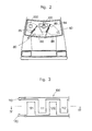
- Figures 3 and 4 show a portion of the rain sensor 100 which is located on the exterior surface of the windshield 84 and is in the vicinity of the change of direction of movement of the wipers 85 within the wiping area 80.
- the rain sensor 100 is made of transparent material (e.g. ln 2 0,(Sn)) so that the occupant can see the outside of the vehicle through the rain sensor 100.
- the rain sensor 100 has a pair of electrodes 110 and 120.
- One of the pair of electrodes 110 has a plurality of projections 111, 112 and so on, and an interval is defined between each two of the plurality of projections 1 11 and 1 1 2.
- Another one of the pair of electrodes 120 has a plurality of projections 121, 122 and so on, and an interval is defined between each two of the plurality of projections 121 and 122. Further, the plurality of projections 111 and 112 of one of electrodes 110 are interleaved into the interval being defined between each two of the projections 121 and 122 of another one of electrodes 120, but a clearance is defined between the plurality of projections 111 and 112 of one of electrodes 110 and the plurality of projections 12 1 and 122 of another one of electrodes 120.
- Each of the pair of electrodes 110 and 120 has a thickness of about one micron and each of electrodes 110 and 120 are fixed on the exterior surface of the windshield 84 by evaporation or sputtering.
- a protector film 150 covers the electrodes 110 and 120 and the protector film 150 is fixed on the electrodes 110 and 120 and the exterior surface of the windshield 84 by evaporation or sputtering.
- the protector film 150 is made from transparent material (e.g. Al 2 O 3 ) and the protector film 150 has a thickness of about one-fifth micron over the electrodes 110 and 120.
- the rain sensor 100 has the above mentioned structure so that the rain sensor 100 forms a plurality of floating capacitors C, through C, between the electrodes 110 and 120 as shown in Figure 4.
- the ftoating capacitors C,, C s and C are formed between the projections 121 and 111 of the electrodes 120 and 1 10, and the floating capacitors C 2 , C, and C 3 are formed between the projections 111 and 122 of the electrodes 110 and 120, further the floating capacitors C 3 , C, and C4 are formed between the projections 122 and 112 of the electrodes 120 and 110.
- the floating capacitors C., C6 and C are of variable capacitance, and when a drop of water is positioned on a portion of the protector film 150 defined between the projections 121 and 111 of the electrodes 120 and 110, the capacitance of the floating capacitor C, becomes more than a normal capacitance of the floating capacitor C s because the dielectric constant of the drop of water is greater than the dielectric constant of air. Accordingly, when many drops of water are positioned on the protector film 150, a total capacitance formed between the electrodes 110 and 120 becomes larger. Further, the total capacitance is approximately in proportion to the amount of drops of water positioned on the protector film 1 50.
- FIG. 5 shows the enlarged wiping area 80 wherein the rain sensor 100 is located near an apex of the wiping area 80 and numeral 88 indicates the initial position of the wiper 85.
- "t” indicates a time period defined between the time when the wiper 85 wipes out the rain sensor 1 00 and the time when the wiper 85 returns to the initial position 88 of the wiper 85.
- the wiper 85 can move at the high wiping speed during the long time period "t 2 " before the timer means 500 outputs the logic level "1" clock signal, and the wiper 85 can move at the low wiping speed during the short time period "t,” before the timer means 500 outputs the logic level "1" clock signal.
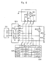
- Figures 6 and 7 show the circuit of the apparatus for controlling a wiper according to the present invention.
- Numeral 801 indicates a motor for driving the wiper 85 and numeral 802 indicates another motor for pumping up water and for emitting water from a washer nozzle (not shown in drawings) to the wiping area 80 of the windshield 84.
- Numeral 805 indicates a wiper switch and numeral 900 indicates a control circuit.
- the motor 801 is a conventional motor which can drive the wiper 85 at high or low wiping speed, and the motor 80 1 includes a stop switch 35.
- the stop switch 35 of the motor 801 When the wiper 85 is positioned at the initial position 88 of the wiper 85, the stop switch 35 of the motor 801 is positioned at a position which is shown by a solid line in Figure 6 and stops the movement of the wiper 85. Accordingly, when the wiper 85 is driven by the motor 801 the stop switch 35 is turned to a position which is shown by a phantom line in Figure 6.
- the stop switch 35 outputs logic level "1" or "0" signal as shown in Figure 8 (E).
- the wiper switch 805 includes a low wiping speed switch, a high wiping speed switch, an off switch and an auto wiping speed switch. When the wiper switch 805 is operated by manual operation and selects the low wiping speed switch, the wiper 85 is driven at the low wiping speed.
- the wiper 85 when the wiper switch 805 selects the high wiping speed switch, the wiper 85 is driven at the high wiping speed. In a similar manner, when the wiper switch 805 selects the off switch, the wiper 85 is not driven by the motor 801. Further, if the wiper switch 805 selects the auto switch, the wiper 85 is driven in accordance with the detected amount of rain positioned on the rain sensor 100 after the wiper 85 wipes out the rain sensor 100.
- a terminal " + B” is electrically connected to a terminal " + 1 ", as a reuslt, a brush 811 of the motor 801 is connected to a battery 803 through an ignition switch 804, accordingly, the motor 801 is driven at the low speed.
- the wiper switch 805 selects the high wiping speed switch, the terminal " + B” is electrically connected to a terminal "+2", as a result, another brush 812 of the motor 80 1 is connected to the battery 803 through the ignition switch 804, accordingly, the motor 801 is driven at the high speed.
- a terminal "S” is electrically connected to the terminal " +1", as a result, a moveable contact of the stop switch 35 is connected to the brush 811 of the motor 801, through a first switch 34 and a second switch 74 of a control circuit 900.
- the first and second switches 34 and 74 are normally connected respectively to non-moveable contacts "S m " and "S S ", as shown by the solid line in Figure 6.
- the wiper switch 805 selects the auto wiping switch
- the terminal "S” is electrically connected to the terminal "+1" and a terminal “C” is electrically connected to a terminal "E”.
- a non-moveable contact "C” of the control circuit 900 is connected to the ground and then the control circuit 900 is connected to the battery 803.
- the wiper switch 805 includes a washer switch 806.
- the washer switch 806 When the washer switch 806 is turned on, the terminal "E" is electrically connected to a terminal "W" independent of selection of the wiper switch 805, as a result, the another motor 802 is electrically connected to the battery 803 through the ignition switch 804 and the terminal "W" is connected to the ground.
- the control circuit 900 is electrically connected to the rain sensor 100.
- the control circuit 900 receives signals detected by the rain sensor 100 being in proportion to the amount of rain, which is positioned on the rain sensor 100 after the wiper 85 wipes out the rain sensor 100.
- the first switch 34 of the control circuit 900 is turned as shown by the phantom line in Figures 6 and 7 during a certain time, as a result, the motor 801 is driven at the low speed and the wiper 85 moves from the initial position 88 of the wiper 85 to an intermediate portion of the wiping area 80.
- the wiper switch 805 selects the auto wiping switch
- the first and second switch 34 and 74 of the control circuit 900 are turned as shown by the phantom line in Figures 6 and 7, as a result, the motor 801 is driven at the high speed.
- the control circuit 900 includes, the first comparator means 200, the actuator means 300, the second comparator means 400, the timer means 500, the memory means 600 and the changing means 700.
- the first comparator means 200 is electrically connected to the rain sensor 1 00, the actuator means 300 and the second comparator means 400.
- the first comparator means 200 compares the amount of rain detected by the rain sensor 100 with the small predetermined amount of drops of water and determines the detected amount of rain is equal to or greater than the small predetermined amount of drops of water, the first comparator means 200 outputs the first actuating signal, which has a logic level "1", to the actuator means 300.
- the first comparator means 200 includes an oscillator 21, one-shot circuit 22, a resistor 23, a condenser 24 and a comparator 25.
- the oscillator 21 is of a conventional resistor-condenser negative feedback type- oscillator which includes an operational amplifier as outputting means of the oscillator.
- the oscillator 21 is connected to the rain sensor 100. When the rain sensor 100 varies its variable capacitance in proportion to amount of rain positioned on the rain sensor 100, the oscillator 21 outputs a frequency which varies in inverse proportion to amount of rain positioned on the rain sensor 100.
- the one-shot circuit 22 receives the output frequency and outputs a signal which has the same period as a period of the output frequency and which has a constant width in spite of the magnitude of the output frequency.
- An integration circuit which consists of the resistor 23 and the condenser 24, receives the signal outputted from the one-shot circuit 22 and the integration circuit outputs voltage signal being in proportion to the output frequency outputted from the oscillator 2 1 . Accordingly, the voltage signal is in inverse proportion to the detected amount of rain, as shown in Figure 8 (A).
- the comparator 25 receives the voltage signal and the comparator 25 compares the value of the voltage signal with a first predetermined value of voltage "V,”. When the comparator 25 determines the value of the voltage signal is equal to or less than the first predetermined value of voltage "V,”, the comparator 25 outputs the first actuating signal which has logic level "1", as shown in Figure 8(B).
- the first predetermined value of voltage "V,” corresponds to the small predetermined amount of drops of water.
- the comparator 25 determines the value of the voltage signal is greater than the first predetermined value of voltage "V,” the comparator 25 output the another actuating signal which has logic level "0". Namely, only when the comparator means 200 determines the detected amount of rain is equal to or greater than the small predetermined amount of drops water, the comparator means 200 outputs the logic level "1" first actuating signal.
- the actuator means 300 When the actuator means 300 receives the logic level "1" first actuating signal from the comparator means 200, the actuator means 300 has the moveable contact of the first switch 34 turn from the position shown by the solid line to the position shown by the phantom line in Figure 7 and maintains the moveable contact of the first switch 34 at the phantom line position during the certain time period.
- the actuator means 300 includes one-shot circuit 31, a NAND gate 39, a switching transistor 32, the first relay 33 and the first switch 34.
- a terminal "0" of the one-shot circuit 31 outputs a pulse signal which has logic level "1" during the certain time period, as shown in Figure 8 (C).
- the switching transistor 82 When the switching transistor 82 receives the logic level "1" pulse signal from the one-shot circuit 31, the switching transistor 82 allows electric current to pass therethrough. As a result, the first relay 33 is actuated and the first switch 3 4 is turned from the solid line position to the phantom line position as shown in Figure 7. Accordingly, when the wiper switch 805 selects the auto wiping switch, the brush 811 of the motor 801 is connected to the battery 803 through the terminals " + 1 " and "S” of the wiper switch 805, the second and first switches 74 and 34, and the ignition switch 804, as a result, the wiper 85 moves at the low wiping speed.
- the certain time period, during which the one-shot circuit 31 outputs pulse signal is longer than a time period defined between a time when the motor 801 is actuated (i.e. the wiper 85 starts moving from the initial position 88 of the wiper 85) and a time when the stop switch 35 is turned from' the solid line position to the phantom line position, as shown in Figure 6.
- the NAND gate 39 receives a feedback signal outputted from the one-shot circuit 31 during the certain time period, as a result, a further logic level "1" first actuating signal is not inputted from the first comparator means 200 to the one-shot circuit 31 of the actuator means 300 during the certain time period.
- the one-shot circuit 31 when the one-shot circuit 31 outputs the logic level "1" pulse signal during the certain time period, the one-shot circuit 3 1 also outputs the feedback signal to the NAND gate 39. As a result, the NAND gate 39 outputs a signal to the one-shot circuit 31 regardless of the logic level "1" first signal outputted from the first comparator means 200.
- the comparator 25 when the wiper 85 wipes out greater than small predetermined amount of drops of water from the rain sensor 100 the comparator 25 outputs the logic level "1" first actuating signals as shown by a,b,c in Figure 8 (B). However, when the one-shot circuit 3 1 outputs the further logic level "1" pulse signal during the certain period, the one-shot circuit 31 does not receive the logic level "1" first actuating signal from the first comparator means 200 even when greater than the small predetermined amount of drops of water is present on the rain sensor 100 with the wiper 85.
- the comparator 25 of the first comparator means 200 outputs the logic level "1" first actuating signal but the one-shot circuit 31 does not output any logic level "1" pulse signal again during the certain time period.
- the one-shot circuit 31 outputs only one of the logic level "1" pulse signal.
- the wiper 85 is continuously actuated, as shown in Figure 8 - (C)
- the one-shot circuit 31 outputs continuously the logic level "1" pulse signal.
- the actuator means 300 includes a clear circuit 36 and a low pass filter 37.
- the clear circuit 36 outputs a clear signal when the first switch 34 is positioned as shown by the solid line in Figures 6 and 7 and the stop switch 35 is positioned as shown by the solid line in Figure 6.
- the clear circuit 36 includes a low pass filter and an inverter and the clear signal outputted from the clear circuit 36 is inputted into each terminals "CL" of delay type flip flops - (i.e., delay type bistable multivibrators) 51, 61 and 71, as a result, the delay type flip flops 51, 61 and 71 are cleared.
- the low pass filter 37 prevents the signal of the stop switch 35 from chattering.
- the signal outputted from the low pass filter 37 is inputted into the timer means 500 and the signal from the low pass filter 37 is concurrently inverted by an inverter 38 and then is inputted into terminals "CP" of the delay type flip-flops 51 and 71.
- the second comparator means 400 includes a comparator 41 which outputs the second actuating signal which has logic level "1", when the comparator 41 determines the voltage signal outputted from the condenser 24 is equal to or less than a second predetermined value of voltage "V,", as shown in Figure 8 (D). (i..e., When the comparator means 400 determines the detected amount of rain is equal to or greater than the large predetermined amount of drops of water, the comparator means 400 outputs the second actuating signal which has logic level "1").
- the memory means 600 includes the delay type flip flop 61 and the logic level "1" second actuating signal is inputted into a terminal "D" of the flip-flop 61 of the memory means 600.
- a terminal "CP" of the flip-flop 6 1 receives the clock signal which has logic level “1” and the logic level “1” second actuating signal is inputted in the terminal "D” of the flip-flop 61 of the memory means 600, the flip-flop 61 outputs an output signal, which has logic level "1", from the terminal "Q" thereof.
- the changing means 700 includes the delay type flip-flop 71, a NAND gate 75, a switching transistor 72, the second relay 73 and the second switch 74.
- a terminal “D" of the flip-flop 71 receives the output signal outputted from the flip-flop 61 of the memory means 600.
- the flip-flop 71 memorizes the output signal outputted from the flip-flop 61 and outputs the change output signal, which has logic level "1", from a terminal "Q" of the flip-flop 71.
- the NAND gate 75 closes and the switching transistor 72 does not receive any signal.
- the one-shot circuit 31 of the actuator means 300 does not output the signal which has logic level "1".
- the switching transistors 32 and 72 do not receive any signal and do not pass the electric current therethrough and then the first and second relays 33 and 73 are deactivated.
- the first and second switches 34 and 74 are turned from the position shown by the phantom line to the position shown by the solid line is Figures 6 and 7.
- the battery 803 is connected to the brush 811 of the motor 801 through the ignition switch 804, the stop switch 35 whose moveable contact is positioned in the position shown by the phantom line in Figure 6, the first and second switches 34 and 74 and the terminals "S" and “+ 1 " of the wiper switch 805, as a result, the motor 801 is driven at the low speed unless the moveable contact of the stop switch 35 is turned from the position shown by the phantom line to the position shown by the solid line in Figure 6. (i.e., The wiper 85 is driven at the low wiping speed until the wiper 85 returns to the initial position 88 of the wiper 85.)
- the timer means 500 outputs a clock signal, which has logic level "0", during the long or short time period "t 2 " or “t,” after the wiper 85 returns to the initial position 88.
- the time means 500 outputs the logic level "0" clock signal during the long time period "t.” after the wiper 85 returns to the initial position 88.
- the timer means 500 outputs the logic level "0" clock signal during the short time period "t,” after the wiper 8 5 returns to the initial position 88.
- the time period "t,” which is defined between the time when the wiper 85 wipes out the rain sensor 100 and the time when the wiper 85 reaches to the initial position 88 of the wiper 85, shown in Figure 5 depends on the low or high wiping speed (e.g., when the wiper 85 is driven at the high wiping speed, the time period “t 1(hi) " is rather short, on the other hand, if the wiper 85 is driven at the low wiping speed, the time period "t 1(low) " is rather long).
- a time period "t, ( hi )" + “t,” and a time period “t 1(low) " + “t 3 " are determined to be the substantially same as the predetermined constant time period.
- the flip-flop 61 of the memory means 600 memorizes the logic level "1" second actuating signal outputted from the second comparator means 400 and reproduces the memorized second output signal when the predetermined constant time period has passed after the wiper 85 had wipes out the rain sensor 100.
- the memory means 600 reproduces the logic level "1" memorized second actuating signal at the time when the time period "t 1(hi) " + "t 2 " has passed after the wiper 85 had wiped out the rain sensor 100.
- the memory means 600 reproduces the logic level "1" memorized second actuating signal at the time when the time period "t,( Lo )" + "t z " has passed after the wiper 85 had wiped out the rain sensor 100.
- the timer means 500 includes the delay type flip-flop 51, NAND gates 53a and 53b, condensers 54a and 54b, inverters 55a and 55b and an OR gate 56.
- the delay type flip-flop 51 memorizes either the logic level “1” or logic level “0” change output signal which is outputted from the "0" terminal of the flip-flop 71 of the changing means 700 and outputs logic level "1” or logic level “0” signal to the NAND gates 53a and 53b at the time the moveable contact of the stop switch 35 is turned to the solid line position shown in Figure 6, (i.e. when the wiper 85 returns to the initial position 88).
- the memorized signal has logic level "1"
- the NAND gate 5 3a opens and the NAND gate 53b closes.
- the NAND gate 53a closes and the NAND gate 53b opens. Concurrently, the signal is inputted from the low pass filter 37 to the NAND gates 53a and 53b.
- the condenser 54a and the inverter 55a are connected to the output side of the NAND gate 53a and the NAND gate 53a, the condenser 54a and the inverter 55a produce the long time period signal "t 2 " which has logic level "0".
- the condenser 54b and the inverter 55b are connected to the output side of the NAND gate 53b and the NAND gate 53b, the condenser 54b and the inverter 55b produce the short time period signal "t," which has logic level "0".
- the signals outputted from the inverter 55a or 55b are inputted to the OR gate 56 and a terminal "CP" of the flip-flop 61.
- the condenser 54b starts to discharge at a time when the logic level "1" output signal is outputted from the stop switch 35 through the low pass filter 37, (i.e., the stop switch 35 is turned from the position shown by the solid line to the position shown by the phantom line in Figure 6), and the condenser 54b discharges after the logic level "1" output signal is outputted from the stop switch 35.
- the inverter 55b outputs a signal, which has logic level "1", to a terminal "CP" of the flip-flop 61 through the OR gate 56 at the short time period "t.” after the wiper 85 returns to the initial position 88 of the wiper 85, as shown in Figure 8 (G).
- the condenser 54a starts to discharge at a time when the logic level "1" output signal is outputted from the stop switch 35 through the low pass filter 37, and the condenser 54a discharges after the logic level "1" output signal is outputted from the stop switch 35. Accordingly, the inverter 55a outputs a signal, which has logic level “1” to the terminal "CP" of the flip-flop 61 through the OR gate 56 at the long time period "t 2 " after the wiper 85 returns to the initial position 88 of the wiper 85, as shown in Figure 8 (G).
- numeral 91 indicates a voltage regulator which is connected between terminals " + B" and "E” of the control circuit 900.
- an output terminal 92 outputs a constant voltage (i.e., 5V) which is supplied to all means of the control circuit 900.
- control circuit 900 includes a delay circuit - (not shown in drawings) which supplies the current to the first relay 33 a few seconds after the washer switch 806 is turned on.
- the first switch 34 is turned from the position shown by the solid line to the position shown by the phantom line in Figure 7 and then the brush 811 of the motor 801 is connected to the battery 803 through the ignition switch 84, the first and second switch 34 and 74 and the terminals "S" and " + 1 " of the wiper switch 805.
- the apparatus for controlling wiper assumes the automatic operation condition.
- the automatic operation condition when the rain sensor 100 detects equal to or greater than the small predetermined amount of drops of water, the comparator 25 of the first comparator means 200 outputs the logic level "1" first actuating signal to the actuator means 300, accordingly, the one-shot circuit 31 of the actuator means 300 outputs the pulse signal to the switching transistor 32 and the moveable contact of the first switch 34 is turned by the first relay 33 to the position shown by the phantom line in Figures 6 and 7.
- the brush 8 1 1 of the motor 801 is connected to the battery 803 through the terminals "S" and “+ 1 " of the wiper switch 805 and the first and second switches 34 and 74 of the control circuit 900 and the ignition switch 804 and the motor 801 is driven at the low wiping speed.
- the comparator 41 of the second comparator means 400 outputs the logic level "1" second actuating signal to the memory means 600.
- the memory means 600 memorizes the logic level “1” second actuating signal and then the flip-flop 61 of the memory means 600 outputs the logic level “1” or logic level “0” actuating signal to the flip-flop 71 of the changing means 700 at the long or short time period "t 2 " or "t,” after the wiper 85 returns to the initial position 88 of the wiper 85.
- the memory means 600 When the wiper 85 returns to the initial position 88 at the high wiping speed, the memory means 600 outputs the logic level “1” or logic level “0" actuating signal at the long time period "t z " after the wiper 85 returns to the initial position 88. On the other hand, when the wiper 85 returns to the initial position 88 at the low wiping speed, the memory means 600 outputs the logic level “1” or “0” actuating signal at the short time period "t,” after the wiper 85 returns to the initial position 88.)
- the motor 801 has the wiper 85 move from and return to the initial position 88 at the high wiping speed.
- the flip-flop 71 of the changing means 700 memorizes a signal which has logic level "0".
- the flip-flop 51 of the timer means 500 memorizes and outputs another actuating signal which has logic level "0". Then, when the stop switch 35 is turned from the position shown by the solid line to the position shown by the phantom line in Figure 6 at a time "T 2 ", the condenser 54b of the timer means 500 discharges.
- the inverter 55b outputs the logic level "1" clock signal to the terminal "CP" of the flip-flop 61 through the OR gate 5 6, as a result, the flip-flop 61 of the memory means 600 reproduces the logic level "0" second actuating signal outputted from the comparator 41 of the second comparator means 400 at the time "T,”.
- the wiping speed of the motor 801 is changed from the high wiping speed to the low wiping speed, and then when the stop switch 35 is turned from the position shown by the solid line to the position shown by the phantom line at a time "T S ", the condenser 54a of the timer means 500 discharges.
- the inverter 55a outputs the clock signal to the terminal "CP" of the flip-flop 61 of the memory means 600 through the OR gate 56.
- the time period "t 2 " or "t,” defined between the time when the wiper 85 returns to the initial position 88 and the time when the flip-flop 61 of the memory means 600 outputs the signal depends on the wiping speed at which the wiper 85 has wiped out on the wiping area 80 of the windshield 84. (i.e., When the wiper 85 has wiped out the windshield 84 at the high wiping speed and when the second comparator 400 outputs the logic level "0" second actuating signal, the flip-flop 61 of the memory means 600 outputs the logic level "0" signal the long time period "t,” after the wiper 85 returns to the initial position 88.
- the flip-flop 61 outputs logic level "0" signal the short time period "t," after the wiper 85 goes from the initial position 88.
- the one-shot circuit 31 of the actuator means 300 outputs the logic level "1" signal and the comparator 25 of the first comparator means 200 does not output the logic level "1" first actuating signal
- the one-shot circuit 31 outputs the logic level "0" signal the certain time period after the one-shot circuit 3 1 outputs the logic level "1" pulse signal and the switching transistor 32 does not allow the electric current to pass therethrough.
- the first switch 34 is turned from the position shown by the phantom line to the position shown by the solid line in Figure 7, so that the wiper motor 801 is not driven.
- the clear circuit 36 outputs a clear signal to each terminal "CL" of the flip flops 51, 61 or 71, so that the flip-flops 51, 61 and 71 are initiated.
- FIG. 9 shows a control circuit 901 of second embodiment according to the present invention.
- This second embodiment is very similar to the first embodiment described above. Differences between the first and second embodiments are that the control circuit 901 of the second embodiment includes a second comparator means 401 and that a rain sensor 100 is directly connected to the second comparator means 401.
- the second comparator means 401 includes an oscillator 42, one-shot circuit 43, a resistor 44, a condenser 45 and a comparator 41.
- the oscillator 4 2 is of a conventional resistor-condenser negative feedback type- oscillator which includes an operational amplifier as the outputting means of the oscillator.
- the oscillator 42 is connected to the rain sensor 100. When the rain sensor 100 varies its variable capacitance in proportion to amount of rain positioned on the rain sensor 100, the oscillator 4 2 outputs a frequency which varies in inverse proportion to amount of rain positioned on the rain sensor 100.
- the one-shot circuit 43 receives the output frequency and outputs a signal which has the same period as a period of the output frequency and which has a constant width regardless of the magnitude of the output frequency.
- An integration circuit which consists of the resistor 44 and the condenser 45, receives the signal outputted from the one-shot circuit 43.
- the integration circuit outputs a voltage signal being in proportion to the output frequency outputted from the oscillator 4 2. Accordingly, the voltage signal is in inverse proportion to the detected amount of rain, as shown in Figure 8 (A).
- the comparator 41 receives the voltage signal and the comparator 41 compares the value of the voltage signal with a second predetermined value of voltage "V z ".
- the comparator 41 determines the value of the voltage signal is equal or to less than the second predetermined value of voltage "V,” the comparator 41 outputs the second actuating signal which has logic level “1", as shown in Figure 8 (C).
- the second predetermined value of voltage "V” corresponds to the large predetermined amount of drops of water.
- the comparator 41 determines the value of the voltage signal is greater than the second predetermined value of voltage "V 2 ", the comparator 41 outputs the another actuating signal which has logic level "0". Only when the comparator means 401 determines the detected amount of rain is equal to or greater than the large predetermined amount of drops water, the comparator means 401 outputs the logic level "1" second actuating signal.
- a timer means of a micro computer may be employed instead of the timer means 500 of the first embodiment and the micro computer may output the clock signal to the terminal "CL" of the flip-flop 61 of the memory means 600 when the micro computer counts down the long or short time period after the wiper 85 returns to the initial position 88 of the wiper 85 (e.g., the micro computer counts down the long time period "1.” when the wiper 85 had returned to the initial position 88 at the high wiping speed, and when the micro computer counts down “Zero", the memory means 600 outputs the logic level “1” or logic level "0” signal, on the other hand, when the wiper 85 had returned to the initial position 8 at the low wiping speed, the micro computer counts down the short time period "t,” and when the micro computer count down "Zero", the memory means 600 outputs the logic level "1” or logic level "0” signal).
- the inverter 55a or 55b of the timer means 500 may output the logic level "0" clock signal through the OR gate 56 when the wiper 85 goes from the initial position 88 instead when the wiper 85 returns to the initial position 88.
- the present invention overcomes the shortcomings of the apparatus for controlling wipers described in the introductory part of this specification which detects the amount of rain positioned on a rain sensor regardless of the wiping speed of wipers and moves smoothly the wipers at different wiping speeds in accordance with the detected amount of rain.
Landscapes
- Engineering & Computer Science (AREA)
- Automation & Control Theory (AREA)
- Mechanical Engineering (AREA)
- Control Of Direct Current Motors (AREA)
Applications Claiming Priority (6)
| Application Number | Priority Date | Filing Date | Title |
|---|---|---|---|
| JP20645/85U | 1985-02-15 | ||
| JP2064585U JPS61137263U (fr) | 1985-02-15 | 1985-02-15 | |
| JP54226/85U | 1985-04-11 | ||
| JP1985054227U JPS61169850U (fr) | 1985-04-11 | 1985-04-11 | |
| JP1985054226U JPS61169849U (fr) | 1985-04-11 | 1985-04-11 | |
| JP54227/85U | 1985-04-11 |
Publications (2)
| Publication Number | Publication Date |
|---|---|
| EP0191638A2 true EP0191638A2 (fr) | 1986-08-20 |
| EP0191638A3 EP0191638A3 (fr) | 1989-07-19 |
Family
ID=27283123
Family Applications (2)
| Application Number | Title | Priority Date | Filing Date |
|---|---|---|---|
| EP86300976A Withdrawn EP0191639A3 (fr) | 1985-02-15 | 1986-02-12 | Appareil et méthode pour commander un essuie-glace |
| EP86300974A Withdrawn EP0191638A3 (fr) | 1985-02-15 | 1986-02-12 | Appareil et méthode pour commander un essuie-glace |
Family Applications Before (1)
| Application Number | Title | Priority Date | Filing Date |
|---|---|---|---|
| EP86300976A Withdrawn EP0191639A3 (fr) | 1985-02-15 | 1986-02-12 | Appareil et méthode pour commander un essuie-glace |
Country Status (1)
| Country | Link |
|---|---|
| EP (2) | EP0191639A3 (fr) |
Cited By (4)
| Publication number | Priority date | Publication date | Assignee | Title |
|---|---|---|---|---|
| DE4117945A1 (de) * | 1991-05-31 | 1992-12-03 | Trebe Elektronik Inh Joannis T | Elektrische vorrrichtung zur automatischen einschaltung eines scheibenwischers |
| WO1993002898A1 (fr) * | 1991-08-09 | 1993-02-18 | Diego Angosto Martinez | Essuie-glace intelligent |
| FR2734531A1 (fr) * | 1995-05-27 | 1996-11-29 | Bosch Gmbh Robert | Dispositif pour commander un essuie-glace |
| CN115534871A (zh) * | 2022-10-13 | 2022-12-30 | 奇瑞汽车股份有限公司 | 雨量传感器、车辆以及车辆的控制方法 |
Families Citing this family (3)
| Publication number | Priority date | Publication date | Assignee | Title |
|---|---|---|---|---|
| US4705998A (en) * | 1987-02-09 | 1987-11-10 | Steven Alpert | Automatic window wiper control |
| FR2628840B1 (fr) * | 1988-03-18 | 1995-01-27 | Renault | Dispositif electronique de detection de pluie |
| DE4036407C2 (de) * | 1990-11-15 | 1994-06-01 | Telefunken Microelectron | Sensorsystem |
Family Cites Families (13)
| Publication number | Priority date | Publication date | Assignee | Title |
|---|---|---|---|---|
| JPS5439112B2 (fr) * | 1975-01-29 | 1979-11-26 | ||
| DE2649413A1 (de) * | 1976-10-29 | 1978-05-11 | Harald Dipl Phys Dr Morgner | Intervallschalter, insbesondere fuer kraftfahrzeug-scheibenwischanlagen |
| JPS5653942A (en) * | 1979-10-08 | 1981-05-13 | Mazda Motor Corp | Controller for intermittent wiper |
| JPS56120436A (en) * | 1980-02-27 | 1981-09-21 | Nissan Motor Co Ltd | Windshield wiper |
| DE3037579A1 (de) * | 1980-10-04 | 1982-05-19 | Franz Kirsten Elektrotechnische Spezialfabrik, 6530 Bingen | Steuerschaltung fuer einen elektromotor, insbesondere fuer einen scheibenwischermotor eines kraftfahrzeuges |
| FR2498137A3 (fr) * | 1981-01-16 | 1982-07-23 | Quercia Charles | Essuie-glace automatique |
| JPS5889440A (ja) * | 1981-11-20 | 1983-05-27 | Honda Motor Co Ltd | 自動車用ウインドワイパ−の操作装置 |
| DK146959C (da) * | 1981-12-08 | 1984-08-06 | Boeegh Petersen Allan | Viskerrobot med foeler |
| JPS58112856A (ja) * | 1981-12-28 | 1983-07-05 | Nissan Shatai Co Ltd | 間欠ワイパの制御装置 |
| JPS58170654A (ja) * | 1982-03-30 | 1983-10-07 | Nippon Denso Co Ltd | ワイパ制御装置 |
| JPS592957A (ja) * | 1982-06-26 | 1984-01-09 | Toshiba Corp | 車輛用ワイパ−の駆動回路 |
| JPS59140146A (ja) * | 1983-01-28 | 1984-08-11 | Jidosha Denki Kogyo Co Ltd | ワイパ間欠駆動制御装置 |
| JPS59149844A (ja) * | 1983-02-15 | 1984-08-27 | Fujitsu Ten Ltd | オ−トワイパ装置 |
-
1986
- 1986-02-12 EP EP86300976A patent/EP0191639A3/fr not_active Withdrawn
- 1986-02-12 EP EP86300974A patent/EP0191638A3/fr not_active Withdrawn
Cited By (8)
| Publication number | Priority date | Publication date | Assignee | Title |
|---|---|---|---|---|
| DE4117945A1 (de) * | 1991-05-31 | 1992-12-03 | Trebe Elektronik Inh Joannis T | Elektrische vorrrichtung zur automatischen einschaltung eines scheibenwischers |
| WO1993002898A1 (fr) * | 1991-08-09 | 1993-02-18 | Diego Angosto Martinez | Essuie-glace intelligent |
| ES2049632A2 (es) * | 1991-08-09 | 1994-04-16 | Angosto Martinez | Circuito electronico para limpiaparabrisas. |
| FR2734531A1 (fr) * | 1995-05-27 | 1996-11-29 | Bosch Gmbh Robert | Dispositif pour commander un essuie-glace |
| GB2301458A (en) * | 1995-05-27 | 1996-12-04 | Bosch Gmbh Robert | Windscreen wiper control system |
| GB2301458B (en) * | 1995-05-27 | 1997-04-30 | Bosch Gmbh Robert | Apparatus for operating a windscreen wiper |
| US5789888A (en) * | 1995-05-27 | 1998-08-04 | Robert Bosch Gmbh | Arrangement for operating a wiper |
| CN115534871A (zh) * | 2022-10-13 | 2022-12-30 | 奇瑞汽车股份有限公司 | 雨量传感器、车辆以及车辆的控制方法 |
Also Published As
| Publication number | Publication date |
|---|---|
| EP0191639A3 (fr) | 1989-07-12 |
| EP0191639A2 (fr) | 1986-08-20 |
| EP0191638A3 (fr) | 1989-07-19 |
Similar Documents
| Publication | Publication Date | Title |
|---|---|---|
| US4710878A (en) | Apparatus and a method for controlling wiper | |
| US4689536A (en) | Apparatus and a method for controlling a windshield wiper | |
| US4639831A (en) | Sensor for detecting an amount of rain | |
| US4740735A (en) | Apparatus and a method for controlling a wiper | |
| JP2723355B2 (ja) | 自動車用アクセサリのための駆動機構制御装置 | |
| US4705998A (en) | Automatic window wiper control | |
| US5086260A (en) | Wiper apparatus with reversing motor protected from overload | |
| US4320329A (en) | Windshield wiper control circuit | |
| US5245259A (en) | Wiper apparatus for motor vehicle | |
| EP0191638A2 (fr) | Appareil et méthode pour commander un essuie-glace | |
| JPS58105856A (ja) | 自動車用風防ワイパ駆動装置 | |
| EP0192416A2 (fr) | Capteur pour détecter une quantité de pluie | |
| EP0282843B1 (fr) | Circuit de commande pour un dispositif de logement d'essuie-glace | |
| JP2648365B2 (ja) | ワイパの制御方法 | |
| JP3033044B2 (ja) | ワイパ自動制御装置 | |
| JPH06321058A (ja) | ワイパ自動制御装置 | |
| JPH05270362A (ja) | ワイパ装置 | |
| JPS626852A (ja) | 車両用オ−トワイパの制御方法 | |
| JPS61291249A (ja) | 車両用オ−トワイパの制御方法 | |
| JPH04362448A (ja) | ワイパ制御装置 | |
| JPH0826074A (ja) | ワイパー制御装置 | |
| JPH064401B2 (ja) | サイドウインドワイパ装置用駆動装置 | |
| KR0152389B1 (ko) | 자동차용 와이퍼 | |
| JPS6121315Y2 (fr) | ||
| JP2590362Y2 (ja) | 車両用ワイパ制御ユニット |
Legal Events
| Date | Code | Title | Description |
|---|---|---|---|
| PUAI | Public reference made under article 153(3) epc to a published international application that has entered the european phase |
Free format text: ORIGINAL CODE: 0009012 |
|
| AK | Designated contracting states |
Kind code of ref document: A2 Designated state(s): DE FR GB |
|
| PUAL | Search report despatched |
Free format text: ORIGINAL CODE: 0009013 |
|
| AK | Designated contracting states |
Kind code of ref document: A3 Designated state(s): DE FR GB |
|
| STAA | Information on the status of an ep patent application or granted ep patent |
Free format text: STATUS: THE APPLICATION IS DEEMED TO BE WITHDRAWN |
|
| 18D | Application deemed to be withdrawn |
Effective date: 19900120 |
|
| RIN1 | Information on inventor provided before grant (corrected) |
Inventor name: IYODA, MOTOMI |