EP0191738B1 - Vorrichtung zum Schliessen oder Öffnen des Kofferraumdeckels oder der Hecktür eines Kraftfahrzeugs - Google Patents
Vorrichtung zum Schliessen oder Öffnen des Kofferraumdeckels oder der Hecktür eines Kraftfahrzeugs Download PDFInfo
- Publication number
- EP0191738B1 EP0191738B1 EP86830017A EP86830017A EP0191738B1 EP 0191738 B1 EP0191738 B1 EP 0191738B1 EP 86830017 A EP86830017 A EP 86830017A EP 86830017 A EP86830017 A EP 86830017A EP 0191738 B1 EP0191738 B1 EP 0191738B1
- Authority
- EP
- European Patent Office
- Prior art keywords
- release member
- lock cylinder
- servo
- push button
- open position
- Prior art date
- Legal status (The legal status is an assumption and is not a legal conclusion. Google has not performed a legal analysis and makes no representation as to the accuracy of the status listed.)
- Expired
Links
Images


Classifications
-
- E—FIXED CONSTRUCTIONS
- E05—LOCKS; KEYS; WINDOW OR DOOR FITTINGS; SAFES
- E05B—LOCKS; ACCESSORIES THEREFOR; HANDCUFFS
- E05B13/00—Devices preventing the key or the handle or both from being used
- E05B13/10—Devices preventing the key or the handle or both from being used formed by a lock arranged in the handle
- E05B13/105—Devices preventing the key or the handle or both from being used formed by a lock arranged in the handle the handle being a pushbutton
-
- E—FIXED CONSTRUCTIONS
- E05—LOCKS; KEYS; WINDOW OR DOOR FITTINGS; SAFES
- E05B—LOCKS; ACCESSORIES THEREFOR; HANDCUFFS
- E05B13/00—Devices preventing the key or the handle or both from being used
- E05B13/005—Disconnecting the handle
Definitions
- the present invention relates to devices for closing and opening the boot lid or rear hatch of a motor vehicle having a locking mechanism.
- the invention is concerned with a closing and opening device of the type comprising a hollow support body in which a push button carrying a cylinder lock is slidable, and a release member for the locking mechanism which is slidable with the push button and movable relative thereto, as a result of the rotation of the cylinder lock, between an inoperative position corresponding to the locked position of the lock cylinder in which the sliding of the push button does not cause the release of the locking mechanism, and an operative position corresponding to the open position of the lock cylinder in which the sliding of the push button causes the release of the locking mechanism and then, in use, the opening of the boot lid or hatch of the vehicle.
- a device of this type is known from US-A-3304755 wherein an actuating member is rotatable between the operative and inoperative positions and only operable either by using the proper key or by electrical means which are controlled independently of use of the key.
- this prior art document discloses a cylinder lock actuator, comprising a casing, a lock cylinder mounted within said casing for combined rotatable and axially slidable movement relative thereto, said cylinder being adapted to be selectively locked against rotation within said casing and being freely slidable therein at all times, a mechanism operating member to be actuated, and an actuating disc mounted on said cylinder for rotation as a unit therewith or rotation independently thereof and for sliding movement therewith relative to said casing.
- the disc includes an actuating lug extending axially of said cylinder and an ear extending radially thereof.
- Lost motion pin and slot means are provided for connecting said disc and said cylinder for rotation of said disc either in response to selected rotation of said cylinder or independently thereof between an operative position juxtaposing said lug to said operating member for engagement therewith in response to sliding movement of said cylinder and an inoperative position locating said lug remote from said operating member to prevent such engagement.
- Power-operated means are mounted on said casing and means are provided for connecting said power-operated means to said radial ear for rotation of said disc between said positions thereof by said power-operated means independently of rotation of said cylinder and for sliding movement of said disc with said cylinder relative to said power-operating means. Means for selectively energising said power-operated means are also provided.
- a device of this type with a rotatable release member is described also in European Patent Application 143 087 in the name of the same Applicants, the application falling under Article 54(3) of the European Patent Convention. Furthermore in this device, the lock cylinder can take up a second open position to locate the release member in its operative position independently of the condition assumed by the servo-mechanism, which is of the reversible type.
- the object of the present invention is to improve a device of the type disclosed in US-A-3 304 755 so that the lock cylinder can take up a second open position to locate the release member in its operative position independently of the condition assumed by the servo-mechanism.
- this object is achieved by virtue of a device according to claim 1.
- the connecting part of the body of the release member has an aperture which is elongate in the direction of sliding of the release member and the can means include an eccentric pin controlled by the lock cylinder and engaged in an aperture in the body of the release member.
- This aperture has a first elongate arm disposed like the aforesaid aperture and in which the pin is inserted in the first open position of the lock cylinder, and a second elongate arm inclined obliquely to the first arm and in which the pin is inserted in the locked position and in the second open position of the lock cylinder.
- the body of the release member is formed by a single piece of moulded plastics material.
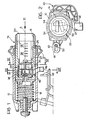
- a hollow cylindrical support body is indicated 10 and is intended to be fitted into an aperture formed in the boot lid or rear hatch, not illustrated, of a motor vehicle, with the interposition of a grommet 12.
- a push button 14 having a hollow initial part 16 is axially slidable in the body 10 against the action of a helical compression spring 18.
- the initial part 16 constitutes the fixed member of a cylinder lock 22 the rotatable cylinder of which is indicated 24.
- the rotatable cylinder 24 is of conventional type and, in known manner, has check plates 26 for cooperating in known manner with axial recesses 25 in the initial part 16.
- the rotatable cylinder 24 has two diametrally- opposed shaped axial appendages 30 at its front end, which are engaged in corresponding recesses 32 in a rotor 34.
- the rotor 34 carries an axial pin 36 disposed eccentrically relative to the axis A of the lock 22 and inserted in a recess 38 in a release member, generally indicated 40.
- the release member 40 is constituted by a one- piece body of moulded plastics material slidable within the push button 14 in a direction B perpendicular to the axis A of the lock 22, coincident with the axis of movement of the push button 14.
- the body 40 forms on one side an attachment part 42 with a slot 44 elongate parallel to the direction of movement B, and on its opposite side a radial operating arm 46 disposed beneath the body 10 for cooperating frontally, in the manner explained below, with an operating member 48 whose movement causes the release of the locking mechanism of the boot lid or hatch and then its opening.
- the recess 38 is generally L-shaped with a first elongate arm 38a parallel to the direction of movement B of the member 40 and a second elongate arm 38b inclined slightly to the arm 38a.
- the slot 44 in the member 40 is intended to house slidably a rod 52 forming part of a reversible servo-mechanism, for example of the nut-and-bolt type, operated by a conventional electrical central locking system for the vehicle doors.
- This servo-mechanism is controlled in known manner through the push button or control lever for locking and unlocking the vehicle door at the driver's position.
- the rotatable cylinder 24 of the cylinder lock 2 has, in known manner, a keyhole 54 for receiving a suitable key by which the rotatable cylinder can be rotated.
- the rotatable cylinder 24 of the lock 22 is arranged to take up three different angular positions which will be termed "first open position”, “locked position” and “second open position” below. In these positions, the keyhole 54 is in the positions illustrated in full outline, broken outline and chain lines, respectively, in Figure 2.
- the movement from the first open position to the locked position is effected by rotation of the cylinder 24 through 90° in a clockwise sense, and the movement from the locked position to the second open position is effected by further rotation of the cylinder 24 through about 75° in the clockwise sense.
- the first open position corresponds to the condition of engagement of the servo-mechanism with the key being removable.
- the release member 40 and its control member 46 can assume the configuration illustrated in Figure 3 or that illustrated in Figure 5 according to the command received from the servo-mechanism.
- the release member 40 In the first case ( Figure 3) the release member 40 is in the inoperative position with the control part 46 spaced from the operating member 48, while in the second case ( Figure 5) the release member 40 is in the operative position with the control part 46 frontally facing the operating member 48.
- the movement of the release member 40 between the operative and inoperative positions is achieved automatically by means of the rod 52 of the servo-mechanism which, as stated previously, is controlled by the electrical central locking system for the vehicle doors: the condition of Figure 5 corresponds to the unlocked position of the push button or locking lever and unlocks the driver's door, while the condition of Figure 3 corresponds to the locked position of this lever or push button. Consequently, the opening of the boot lid or hatch of the vehicle is prevented when the central locking system is in the locked condition, while. the boot lid or hatch can be opened when the system is in the unlocked condition.
- the servo-mechanism allows the release member 40 to be positioned automatically in the inoperative position in which operation of the member 48 is prevented, even in the operative position in which this operation would be allowed.
- relative movement is achieved between the eccentric pin 36, which remains stationary, and the arm 38a of the aperture 38 of the release member 40.
- the eccentric pin 36 In the closed position of the lock 22 illustrated in Figure 6, in which the key can be removed, the eccentric pin 36 is rotated through 90° in a clockwise sense relative to the position of Figure 5 and is disposed in the initial zone of the arm 38b of the aperture 38, and the release member 40 is kept in the inoperative position.
- the part 46 of the member 40 is spaced from the operating member 48 so that the opening of the boot lid or hatch of the vehicle is always prevented and cannot be enabled even by the servo-mechanism, whatever the position assumed by the push button or lever for locking and unlocking the driver's door.
- the eccentric pin 36 is disposed in correspondence with the end portion of the arm 38b of the aperture 38, in the manner illustrated in Figure 7.
- the release member 40 is again disposed in the operative position with the part 46 facing the member 48 frontally, so that the boot lid or hatch of the vehicle can be opened by a push on the push button 14 whatever the position assumed by the servo-mechanism.
Landscapes
- Lock And Its Accessories (AREA)
Claims (3)
Applications Claiming Priority (2)
| Application Number | Priority Date | Filing Date | Title |
|---|---|---|---|
| IT5298485U | 1985-02-11 | ||
| ITTO1985U52984U IT8552984U1 (it) | 1985-02-11 | 1985-02-11 | Dispositivo di chiusura e apertura del coperchio del baule o portello nel posteriore di un autoveicolo. |
Publications (3)
| Publication Number | Publication Date |
|---|---|
| EP0191738A2 EP0191738A2 (de) | 1986-08-20 |
| EP0191738A3 EP0191738A3 (en) | 1988-09-14 |
| EP0191738B1 true EP0191738B1 (de) | 1990-08-22 |
Family
ID=11279058
Family Applications (1)
| Application Number | Title | Priority Date | Filing Date |
|---|---|---|---|
| EP86830017A Expired EP0191738B1 (de) | 1985-02-11 | 1986-01-22 | Vorrichtung zum Schliessen oder Öffnen des Kofferraumdeckels oder der Hecktür eines Kraftfahrzeugs |
Country Status (4)
| Country | Link |
|---|---|
| EP (1) | EP0191738B1 (de) |
| DE (1) | DE3673535D1 (de) |
| ES (1) | ES292236Y (de) |
| IT (1) | IT8552984U1 (de) |
Families Citing this family (3)
| Publication number | Priority date | Publication date | Assignee | Title |
|---|---|---|---|---|
| DE19956357B4 (de) * | 1999-11-24 | 2006-04-13 | Bayerische Motoren Werke Ag | Schlossentriegelungseinrichtung an einer verstellbaren Klappe oder Tür |
| DE10031249C2 (de) * | 2000-06-27 | 2002-11-28 | Huf Huelsbeck & Fuerst Gmbh | Betätigungsvorrichtung für ein Schloß, insbesondere an einem Fahrzeug |
| US11268301B2 (en) | 2017-04-27 | 2022-03-08 | Reinhard Matye | Automatic hatch for bulk material containers |
Family Cites Families (4)
| Publication number | Priority date | Publication date | Assignee | Title |
|---|---|---|---|---|
| US3304755A (en) * | 1964-10-28 | 1967-02-21 | Gen Motors Corp | Cylinder lock actuator |
| FR2470834A1 (fr) * | 1979-12-04 | 1981-06-12 | Dubois & Cie | Mecanisme de verrouillage pour serrures diverses et son application a des serrures de vehicules en particulier de coffres a actionnement manuel ou electrique |
| FR2527255B1 (fr) * | 1982-05-19 | 1988-07-29 | Neiman Sa | Serrure a barillet a deux positions stables |
| IT8353963V0 (it) * | 1983-11-21 | 1983-11-21 | Fiat Auto Spa | Dispositivo di chiusura e apertura del coperchio del baule o portellone posteriore di un autoveicolo |
-
1985
- 1985-02-11 IT ITTO1985U52984U patent/IT8552984U1/it unknown
-
1986
- 1986-01-22 EP EP86830017A patent/EP0191738B1/de not_active Expired
- 1986-01-22 DE DE8686830017T patent/DE3673535D1/de not_active Expired - Fee Related
- 1986-02-10 ES ES1986292236U patent/ES292236Y/es not_active Expired
Also Published As
| Publication number | Publication date |
|---|---|
| EP0191738A3 (en) | 1988-09-14 |
| ES292236Y (es) | 1987-04-16 |
| DE3673535D1 (de) | 1990-09-27 |
| ES292236U (es) | 1986-08-01 |
| EP0191738A2 (de) | 1986-08-20 |
| IT8552984V0 (it) | 1985-02-11 |
| IT8552984U1 (it) | 1986-08-11 |
Similar Documents
| Publication | Publication Date | Title |
|---|---|---|
| EP0693605B1 (de) | Verriegelungseinrichtung mit einer Riegelfunktion | |
| US4440006A (en) | Antitheft central lock system for a motor vehicle | |
| US3999411A (en) | Lock knob control mechanism | |
| EP0942134B1 (de) | Elektrischer Schliessmechanismus mit einer zusätzlichen türinnenseitigen mechanischen Entriegelungseinrichtung | |
| US5899508A (en) | Double locking vehicle door latch | |
| US5423582A (en) | Power-assist motor-vehicle door latch | |
| US6059327A (en) | Latch system for a trunk lid of an automobile | |
| US6575003B1 (en) | Door lock for a vehicle with electrical locking/unlocking | |
| JPH041834B2 (de) | ||
| ES2011933A6 (es) | Cerradura de puerta para automoviles. | |
| JPH0443147B2 (de) | ||
| US6007117A (en) | Motor vehicle door lock or the like with trip-free mechanism | |
| US4936895A (en) | Releasable lock with a rotable stator | |
| GB1317917A (en) | Door latch | |
| US4643006A (en) | Lock having an external bolt unlocking device | |
| GB2155535A (en) | Motor vehicle door lock | |
| US4554808A (en) | Exterior control for a vehicle door provided with an electric latch | |
| EP0191738A2 (de) | Vorrichtung zum Schliessen oder Öffnen des Kofferraumdeckels oder der Hecktür eines Kraftfahrzeugs | |
| GB2024924A (en) | Steering column locks | |
| EP0143087B1 (de) | Vorrichtung zum Öffnen und Schliessen eines Kofferraumdeckels oder Gatterwandes eines Kraftfahrzeuges | |
| US6360572B1 (en) | Motor vehicle opening leaf handle comprising operated disengageable means for operating a lock | |
| ES8100413A1 (es) | Perfeccionamientos en las cerraduras de puerta de vehiculos a motor | |
| US20020190530A1 (en) | Manually lockable motor-vehicle power latch | |
| CA2264668C (en) | Double locking vehicle door latch | |
| EP0829602B1 (de) | Kraftfahrzeug-Türschloss |
Legal Events
| Date | Code | Title | Description |
|---|---|---|---|
| PUAI | Public reference made under article 153(3) epc to a published international application that has entered the european phase |
Free format text: ORIGINAL CODE: 0009012 |
|
| AK | Designated contracting states |
Kind code of ref document: A2 Designated state(s): DE FR GB IT |
|
| PUAL | Search report despatched |
Free format text: ORIGINAL CODE: 0009013 |
|
| RHK1 | Main classification (correction) |
Ipc: E05B 13/10 |
|
| AK | Designated contracting states |
Kind code of ref document: A3 Designated state(s): DE FR GB IT |
|
| 17P | Request for examination filed |
Effective date: 19881104 |
|
| 17Q | First examination report despatched |
Effective date: 19890220 |
|
| GRAA | (expected) grant |
Free format text: ORIGINAL CODE: 0009210 |
|
| AK | Designated contracting states |
Kind code of ref document: B1 Designated state(s): DE FR GB IT |
|
| ITF | It: translation for a ep patent filed | ||
| REF | Corresponds to: |
Ref document number: 3673535 Country of ref document: DE Date of ref document: 19900927 |
|
| ET | Fr: translation filed | ||
| PLBE | No opposition filed within time limit |
Free format text: ORIGINAL CODE: 0009261 |
|
| STAA | Information on the status of an ep patent application or granted ep patent |
Free format text: STATUS: NO OPPOSITION FILED WITHIN TIME LIMIT |
|
| 26N | No opposition filed | ||
| ITTA | It: last paid annual fee | ||
| PGFP | Annual fee paid to national office [announced via postgrant information from national office to epo] |
Ref country code: GB Payment date: 19931210 Year of fee payment: 9 |
|
| PGFP | Annual fee paid to national office [announced via postgrant information from national office to epo] |
Ref country code: DE Payment date: 19931217 Year of fee payment: 9 |
|
| PG25 | Lapsed in a contracting state [announced via postgrant information from national office to epo] |
Ref country code: GB Effective date: 19950122 |
|
| GBPC | Gb: european patent ceased through non-payment of renewal fee |
Effective date: 19950122 |
|
| PG25 | Lapsed in a contracting state [announced via postgrant information from national office to epo] |
Ref country code: DE Effective date: 19951003 |
|
| PGFP | Annual fee paid to national office [announced via postgrant information from national office to epo] |
Ref country code: FR Payment date: 19960129 Year of fee payment: 11 |
|
| PG25 | Lapsed in a contracting state [announced via postgrant information from national office to epo] |
Ref country code: FR Effective date: 19970930 |
|
| REG | Reference to a national code |
Ref country code: FR Ref legal event code: ST |
|
| PG25 | Lapsed in a contracting state [announced via postgrant information from national office to epo] |
Ref country code: IT Free format text: LAPSE BECAUSE OF NON-PAYMENT OF DUE FEES;WARNING: LAPSES OF ITALIAN PATENTS WITH EFFECTIVE DATE BEFORE 2007 MAY HAVE OCCURRED AT ANY TIME BEFORE 2007. THE CORRECT EFFECTIVE DATE MAY BE DIFFERENT FROM THE ONE RECORDED. Effective date: 20050122 |