EP0191886A2 - Dispositif pour murer des pierres artificielles de grande taille d'un bâtiment pouvant être climatisé - Google Patents
Dispositif pour murer des pierres artificielles de grande taille d'un bâtiment pouvant être climatisé Download PDFInfo
- Publication number
- EP0191886A2 EP0191886A2 EP85104190A EP85104190A EP0191886A2 EP 0191886 A2 EP0191886 A2 EP 0191886A2 EP 85104190 A EP85104190 A EP 85104190A EP 85104190 A EP85104190 A EP 85104190A EP 0191886 A2 EP0191886 A2 EP 0191886A2
- Authority
- EP
- European Patent Office
- Prior art keywords
- joint
- mortar
- stack
- artificial
- horizontal
- Prior art date
- Legal status (The legal status is an assumption and is not a legal conclusion. Google has not performed a legal analysis and makes no representation as to the accuracy of the status listed.)
- Granted
Links
- 239000004575 stone Substances 0.000 title claims abstract description 34
- 239000002969 artificial stone Substances 0.000 claims abstract description 54
- 238000004378 air conditioning Methods 0.000 claims abstract description 4
- 239000004570 mortar (masonry) Substances 0.000 claims description 52
- 239000011440 grout Substances 0.000 claims description 9
- 238000004140 cleaning Methods 0.000 claims description 4
- XEEYBQQBJWHFJM-UHFFFAOYSA-N Iron Chemical group [Fe] XEEYBQQBJWHFJM-UHFFFAOYSA-N 0.000 claims description 2
- 210000001503 joint Anatomy 0.000 claims 2
- 239000000725 suspension Substances 0.000 claims 1
- 239000011449 brick Substances 0.000 description 22
- 238000010276 construction Methods 0.000 description 9
- 238000003892 spreading Methods 0.000 description 7
- 238000000034 method Methods 0.000 description 4
- 239000006096 absorbing agent Substances 0.000 description 3
- 230000035939 shock Effects 0.000 description 3
- 238000009416 shuttering Methods 0.000 description 3
- 230000001419 dependent effect Effects 0.000 description 2
- 238000003780 insertion Methods 0.000 description 2
- 230000037431 insertion Effects 0.000 description 2
- 238000004804 winding Methods 0.000 description 2
- 235000019738 Limestone Nutrition 0.000 description 1
- 230000001154 acute effect Effects 0.000 description 1
- 239000011230 binding agent Substances 0.000 description 1
- 239000004567 concrete Substances 0.000 description 1
- 238000011109 contamination Methods 0.000 description 1
- 230000008878 coupling Effects 0.000 description 1
- 238000010168 coupling process Methods 0.000 description 1
- 238000005859 coupling reaction Methods 0.000 description 1
- 238000000151 deposition Methods 0.000 description 1
- 238000006073 displacement reaction Methods 0.000 description 1
- 238000009826 distribution Methods 0.000 description 1
- 230000000694 effects Effects 0.000 description 1
- 238000009415 formwork Methods 0.000 description 1
- 239000011810 insulating material Substances 0.000 description 1
- 239000006028 limestone Substances 0.000 description 1
- 239000004033 plastic Substances 0.000 description 1
- 230000036316 preload Effects 0.000 description 1
- 238000003825 pressing Methods 0.000 description 1
- 239000008262 pumice Substances 0.000 description 1
- IHQKEDIOMGYHEB-UHFFFAOYSA-M sodium dimethylarsinate Chemical class [Na+].C[As](C)([O-])=O IHQKEDIOMGYHEB-UHFFFAOYSA-M 0.000 description 1
Images




Classifications
-
- E—FIXED CONSTRUCTIONS
- E04—BUILDING
- E04G—SCAFFOLDING; FORMS; SHUTTERING; BUILDING IMPLEMENTS OR AIDS, OR THEIR USE; HANDLING BUILDING MATERIALS ON THE SITE; REPAIRING, BREAKING-UP OR OTHER WORK ON EXISTING BUILDINGS
- E04G21/00—Preparing, conveying, or working-up building materials or building elements in situ; Other devices or measures for constructional work
- E04G21/14—Conveying or assembling building elements
- E04G21/16—Tools or apparatus
- E04G21/22—Tools or apparatus for setting building elements with mortar, e.g. bricklaying machines
Definitions
- the invention relates to a device for bricking up large-format masonry blocks in an air-conditioned building according to the preamble of claim 1.
- the device according to the invention mechanizes the erection of masonry, in particular the placement of the plastic stones on the brick horizontal joints and is therefore preferably used for artificial stones which due to their dimensions and their weight can no longer be handled by bricklayers.
- artificial stones can consist of limestone, bricks, pumice or concrete and differ from normal stones by their significantly larger dimensions and a correspondingly increased weight.
- Stone heights are between approx. 23.8 to 50.3 cm, but also e.g. 64.0 cm and stone lengths of approx. 2.4 m to 4.2 m, but also considerably less, namely approx. 1.0 m possible.
- Such artificial stones are preferably omitted one or more times.
- the device according to the invention is used for bricking up artificial stones which have up to four continuous vertical channels and recessed edges, the cutouts of the horizontal stone edges in a horizontal joint of the masonry being able to form continuous horizontal channels in the cutouts of adjacent artificial stones.
- vertical and possibly horizontal channels are created by bricking up the walls of a building for guiding an air-conditioning, preferably gaseous medium that heats or cools the building in an open guide or in a closed circuit.
- the crane-supported gripper which is embodied in the device according to the invention, preferably grips the artificial stones in the arrangement in which they are delivered and deposited at the construction site by a precast plant.
- the artificial stones on the construction site do not need to be arranged and put together according to their mutual position in the later masonry, so that the work associated therewith or the devices required to mechanize them are dispensed with.
- the invention is based on a previously known device.
- the gripper detects several artificial stones of simple design and simultaneously places them on the previously grouted horizontal joint of the masonry.
- This device preferably interacts with a frame which serves as an empty space for maintaining the joint height and width. This forms a shuttering of the horizontal joint based on the number recorded by the gripper the joint length specified and serves to fill the mortar on which the artificial stones are placed.
- the invention has for its object to provide a device of the type presupposed as known, which enables a considerable progress in rationalization.
- the device according to the invention characterized in that in the device according to the invention stacks of several superposed stone blocks are stacked, only one artificial stone is on each a horizontal joint, which corresponds to the procedure for professional masonry, but is mechanized.
- the manipulators according to the invention it is achieved that the new device, without pivoting back to the construction site, places all of the artificial stones recorded in a stack of magazines one after the other on mortared horizontal joints. This takes place in a tandem system, which adjusts the artificial stones in the device downwards and releases the artificial stone in the lowest position, but holds the following artificial stone until the magazine is empty.
- the device according to the invention can preferably accommodate three-layer stacks with correspondingly three artificial stones in its magazine.
- the tandem system enables the required artificial stones to be picked up from the delivered stacks and stacked in the magazine. This eliminates the previous effort for the simultaneous acquisition of several selected artificial stones.
- an even more extensive rationalization is achieved in the construction of the masonry described. This is done by mortaring the horizontal and possibly also the vertical joints with a quantity of joint mortar determined by the joint itself and the number of artificial stones detected, with the aid of the device according to the invention with the features of claim 2 carries device according to the invention, you have the correct mortar quantity available and therefore does not need to use the crane separately, nor does it measure the amount of mortar and distribute it on the joints, which is difficult when using mortar pumps and often also leads to contamination of the construction site.
- the amount of mortar required for masonry of each individual artificial stone can be measured and delivered in accordance with the procedure used by professional masonry on or in the relevant horizontal or vertical joint. This considerably facilitates and speeds up the bricking of the artificial stones, whereby the quality of the masonry corresponds exactly to the specification.
- the device required for this can be pivoted out of the clearance profile of the magazine in order to create space for depositing the artificial stone to be placed on the freshly grouted joint .
- the device is provided with the manipulators which, in the tandem system described, permit positive locking of the heavy artificial stones and thereby ensure safety on the construction site.
- claims 9-18 characterize a group of embodiments of the device according to the invention, which is designed to save space and for this purpose accommodates the parts of the manipulators in the recesses of the artificial stones, thus making them usable for the rationalization of the walls.
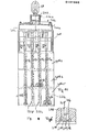
- the device shown in FIG. 1 and generally designated 150 is a scaffold 154 supported by a crane (not shown) via a crane rope 151, ie scaffold 154 suspended thereon with a plurality of shock absorbers 152, 153.
- a shaft 155 is formed, which serves as a magazine for several superimposed masonry stones of the type described, designated 156 to 158 in FIG. 1.
- the gripper which is generally designated 159, interacts with this magazine 155.
- a mortar container 162 is suspended via a linkage 161 so that it can pivot about a hinge arranged at 161 'by means of a hydraulic working cylinder 162' in the direction of the double arrow 163.
- the mortar container 162 can have the operating position shown in solid lines, in which it partially projects with its outlet 164 into and out of the clearance profile of the magazine or shaft Position swiveled into the position shown in dash-dotted lines, in which the clearance profile of the magazine is released.
- the mortar container 162 has a number of pushed-off compartments 165 to 167, corresponding to the number of stored wall artificial stones 156 to 158.
- the gate valves 168 to 170 assigned to the compartments 165 to 167 shut off the space of the relevant compartment below, which is matched to a quantity of mortar which corresponds to the length of a horizontal joint 171 (FIG. 1), which is limited to a longitudinal side 5 of the brick 1.
- FIG. 1 also shows details of the illustrated embodiment of the gripper 159. Its main part consists of lower pliers 172, the pliers legs 173, 174 of which can be adjusted in the direction of the double arrow 176 with the aid of a hydraulic working cylinder 177, 178 (FIG. 2) from the closed position of the pliers shown in the extended position to the open position and vice versa, which is shown in dashed lines.
- the tong joints 179, 180 are attached to the frame 154 on each side of the magazine 155.
- each tong leg is formed by two parallel levers 182, 183, which are moved synchronously by the working cylinders 178, 179 with the aid of a common traverse 184.
- a shock absorber 185, 186 is installed in each lever.
- the lever ends are attached to a bar 187, which together with the adjacent bar of the opposite Pliers leg forms an empty 188 for shuttering the horizontal joint 171 described.
- the strips 187 are in the remaining part of a stone gripper 189, 190, which engages under the sides of the brick 1. Because of the insulating material plate 11, the gripper 189 is longer than the gripper 190 and the pivoting paths of the pliers legs differ according to the length of the gripper.
- the second manipulator according to the exemplary embodiment in FIG. 1 has a further pliers 191 corresponding to the pliers 172, which is similar to the pliers 172 and is opened and closed in accordance with the double arrow 192, which is shown as for the pliers 172 in FIG. 1.
- each leg of the pliers 191 is in turn constructed from parallel levers 193, 194, which are pivoted in their hinges 198, 199 by working cylinders 196, 197 with the aid of a common traverse 195.
- a further mortar container 201 with three compartments 202 to 204 and sliders 205 to 207 closing these are suspended on the front side 200 of the framework 154.
- the outlet 208 of the mortar container 201 is arranged such that it does not protrude into the clearance profile of the magazine 155. Otherwise, the mortar container 201 is also pivotable, as described using the example of the mortar container 162, suspended in the framework 154.
- the crane lifts the scaffold 154 to the place of the wall which is to be built on.
- the framework 154 is first stopped above the joint 171 to be mortared (FIG. 1), so that the mortar container 162 in its operating position with the opening 216 of its mortar outlet 164 points approximately to the center of the mortar joint 171.
- the worker who is working at the wall site now first pulls the slide 168, whereby this process can of course be mechanized with the help of the working cylinder. This frees the amount of mortar contained in compartment 167 and slides through the closed outlet 164 onto the joint 171.
- the mortar container 162 is pivoted into its dot-dash position according to FIG.
- the scaffold 150 is then lowered with the aid of the crane until the strips 187 of the gripper 188 described in connection with FIG. 2 lie against the flanks of the stone shown at 217 of the already existing layer 135 of the masonry.
- the framework 154 is thereby centered on the part of the masonry that is already standing.
- the pliers 172 are then opened. Since the pliers 191 remain closed, only the lower brick 158 comes out of the shaft 155 after the pliers legs have been opened on the mortar of the joint 171.
- the shuttering of the joint prevents the mortar from being able to pass out of the joint when it widens under the pressure of the brick 158 applied.
- the empty strip assigned to the manipulator 189 prevents the grout from reaching the end face of the insulating plate 11.
- the large-format bricks have a total of four identical cams 118, 119 and 120 on the lower side of the stone boundary. These cams form a structural unit with the stone 1 and are dimensioned so that they can break if they have served their purpose. This consists in supporting the still soft grout on the top 4 of the stones of the horizontal masonry layer 135 which is already standing and thereby limiting the height of the joint.
- the slide 207 of the compartment 104 in the mortar container 201 is pulled, as a result of which the mortar contained in this compartment passes through the outlet 208 into the vertical joint 209. Since the amount of mortar is measured, the joint 209 is filled and the flow of mortar through the outlet 208 is automatically stopped as soon as the joint 133 is filled.
- the device 150 can brick a second brick, namely the stone 157 held in the shaft 155.
- the pliers 172 are closed and the pliers 191 are opened.
- the two bricks 156, 157 arranged one above the other slide downward in the magazine 155 until the stone 157 rests on the stone grippers 189, 190, as before the stone 158.
- the shock absorbers 185, 186 described ensure in this process that dangerous dynamic loads on the device are prevented.
- the device 150 After the device 150 has been prepared for bricking the stone 157 in this manner, it operates in a manner corresponding to that described for the bricking of the stone 158.
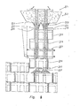
- the embodiment of the device 221 according to FIG. 3 corresponds in all parts of the device 150 with the following exception: above the shaft 155, the mortar container 222 is installed in a stationary manner, which corresponds to the mortar container 162. Accordingly, the container holds the same amount of mortar as the container 162, but has an outlet 223 formed by a downpipe, which via corresponding pipe sockets 224, 225 connects to the vertical recesses 2, 3 of the stacked in the shaft 155, according to the embodiment of the figure 13 represents a total of four large-format bricks 226 to 229.
- the shaft is open on its narrow sides so that the stones can be arranged one above the other according to the offset in the binder masonry.
- the pants part is the Pipe 223 divided with two pairs of slides 230, 231, which are actuated alternately, whereby the required amounts of mortar are measured. Since the tubes 224, 225 protrude through the mutually aligned recesses 2, 3 of the threaded large-sized stones 226 to 229, they form a guide for the stones 226 to 229 and can with ends from the respective lower stone 226 projecting ends 232, 233 distribute the grout better.
- the mode of operation of the device corresponds to the mode of operation already described in connection with the embodiment according to FIGS.
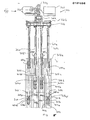
- FIG. 4 shows a device for manipulating masonry stones stacked one above the other and designated 301.
- a cross member 302a is hung by means of an eyelet 303 on the hook of a crane, not shown.
- a longitudinal beam 330 is displaceably mounted opposite the eyelet 303 with the aid of a working cylinder 331a.
- a carrier 332 On the underside of the carrier 330 facing away from the eyelet 303, a carrier 332 is slidably mounted with a cylinder 331b.
- Four pressure medium cylinders 304a ... 304d are attached to this in parallel.
- the pressure medium cylinders 304a .... 304d have piston rods 305a .... 305d.
- spreading elements 306 are arranged in the lower region of the piston rods.
- Figure 5 has each of the same spreading elements 306a ... 306d of two opposed skid-shaped plates 307a, 307b. These plates are angled inwards at both ends. The plates are attached on their inner sides facing the respective piston rods 305a ... 305d to trapezoidal brackets 308a, 308b, on each of which two links 309a ... 309d are rotatably fastened. With their respective other ends, the links 309 are rotatably connected to two sleeves 310 and 311 which enclose the piston rod 305 at a vertical distance from one another. The ends of a helical spring 312 are supported on the two sleeves 310 and 311.
- the cuff 310 is displaceable against the pressure of the helical spring 312 on the piston rod in the longitudinal direction of the piston rod.
- the cuff 311 is supported downward on a shoulder 313 of the piston rod and is thereby fixed, while the upward displacement movement of the cuff 310 is limited by a stop 314.
- This stop 314 forms the lower edge of a tube piece which can be pushed telescopically over the piston rod 305 and which, when pressurized, presses against the sleeve 110 and thus compresses the coil spring.
- the links 309 straighten up from their original position and thereby move the plates 307 outward from the piston rod 305.
- the outer sides of the plates are padded and lie against the walls of the cutouts provided in the finished parts 316a, 316c to be manipulated. After relieving pressure, the plates are tightened using the tensioned screws spring 312 returned to its original position.
- the expansion element 306 here consists of a pressure medium cylinder 317a .... 317d arranged at the lower end of the piston rods 305a .... 305d perpendicular to the longitudinal axis on the piston rod.
- the pressure medium cylinder 317 protrudes both with its end 318 on the piston rod side and with this end 319 opposite the jacket of the piston rod. Both the end 318 and the end 319 of the pressure medium cylinder 317 are provided with rubber pads.
- the piston rod 320 of the pressure medium cylinder 317 extends, the rubber pads pressing against the walls of the cutouts in the brick 316.
- the cutouts 321 are locally widened for the expansion elements 306 in order to give the brick a better hold by means of a positive fit when the expansion element 306 is open.
- the brick 316 used according to the invention in the exemplary embodiment has cutouts 321 which have a rectangular cross section, the corners of this rectangle being rounded.
- the upper part of the recesses 321 is flared. This funnel-shaped widening facilitates the insertion of the expansion elements 316 arranged on the piston rods.
- FIGS. 5 to 10 The operation of the devices described and shown in FIGS. 5 to 10 is as follows: three stacked bricks 316a ... 316c are aligned in such a way that their parallel recesses 321a .... 321d are aligned with the corresponding recesses of the adjacent stones. With the help of a crane, not shown, the device is hung over the eyelet 303 with the piston rods 305a .... 305d retracted over the stack previously constructed from the stones 316a .... 316c. The lower ends of the piston rods 305a ... 305d with the spreading elements 306 attached to them are each located exactly above the widened part 322 of the recess 321. Then the piston rods are extended and the spreading elements are lowered in the recesses 321.
- the piston rods 305a and 305d of the outer pressure medium cylinders 304a and 304d are extended into the recess 321 of the bottom block 316 0 , while the expansion elements 306b and 306c, which are assigned to the two inner pressure medium cylinders 304b and 304c, are extended into the second block 316b.
- the spreading elements 306 then lie against the walls of the recesses 321. If the bottom stone 316c is now to be set down, the spreading elements 306 of the outer cylinders 304a and 304d move back into their starting position and the stone is released. The remaining stones are held on the device by the expansion elements 306b and 306c, which are assigned to the two inner cylinders 304b and 304c.
- the piston rods 305a and 305d of the two outer cylinders 304a and 304d are retracted until the expansion elements 306 are located in the recesses 321 of the uppermost brick 316a.
- the spreading elements 306 are activated again. Then the following brick 316b can be lowered.
- the device 301 is provided with a rigid rectangular tube 334 which is fastened to the carrier 302 with its upper end.
- the tube 334 surrounds the cylinders 317 and the raised stack 335.
- Trusses 336 are fastened to the free end of the tube 334, which have strong electromagnets 337 projecting downwards and baffles 338 and 339 diverging downwards and outwards, which are attached to parallel frame cross beams 340 and 341 are attached.
- the electromagnets 337 cooperate with a frame, not shown, which corresponds to the frame 336 and is placed on the joint in question. Iron cores, which interact with the electromagnets 337, are attached to cross members of this frame.
- the electromagnets 337 are energized, and after a finished part has been deposited from the stack 335 in the manner described above, they are switched off. This way it is possible to use the excited electromagnets 337 to align the device 301 precisely with respect to the joint before a finished part is released from the stack 335 and deposited.
- the eyelet 303 carries an electrical pressure generator for the pressure oil which is required to actuate the various working cylinders described above.
- the parts of the pressure generator are arranged in such a way that with the various cylinders 331a and 331b the device 301 can be adjusted so far in the eyelet 303 that the stack 335 hangs vertically. Therefore, the electric motor 342 is arranged with its axis 343 at an acute angle to the axis of the carrier 332.
- the motor shaft is directly coupled to a hydraulic pump 345 via a coupling 344.
- a pressure vessel 346 is built on the other side of the eyelet 303 ( Figure 5). Schematically ( Figure 8) at 347 the electronics housed in a control cabinet and at 348 the various remote-controlled electro valves for switching the cylinders are shown.
- a strut 349 is used at the ends of the piston rods 305, which makes it easier to locate the local widening 350 of the recess 321 in that their effective parts are resiliently biased outwards so that these Roll parts either on the inner lateral surfaces 351, 352 of the recess 321 when the piston rods 305 move downwards or upwards, which is shown in dashed lines in FIG. 10.
- the effective parts of the spreaders are driven outwards under the action of the spring preload, so that they lie against the inner surfaces 353, 354 of the widenings 350.
- this outward movement possibility is limited to a dimension which facilitates the insertion of the spreaders into the conical starting ends of the cutouts 321, which are not shown in FIG. 10.
- the spreaders consist of rollers or pairs of rollers 355, 356, the bearings of which are mounted on plungers 357, 358, which in turn are attached to the body 360 of the struts on both sides with one or more pendulums suspended at 359 about a transverse axis , coil springs, not shown, are biased.
- the roles are frosted with rubber.
- the body 360 carries on its underside a rubber cushion 361 which is driven downward from the relevant piston rod 305 onto the horizontal joint when the piston rod extends.
- the rubber pad 361 therefore forms an abutment that holds the position in which the rollers 355, 356 engage in the widenings 350. As soon as this happens, the finished part in question is positively locked with the strut.
- ropes or chains can be used with their piston rods 305.
- parallel winding bodies can be accommodated on the carrier 302, each of which accommodates the ropes or chains which take the place of the cylinders 304a, 304d or 304b, 304c.
- the winding bodies are driven by hydraulic motors and run parallel to the longitudinal axis of the carrier 302 or to one another.
Landscapes
- Engineering & Computer Science (AREA)
- Architecture (AREA)
- Mechanical Engineering (AREA)
- Civil Engineering (AREA)
- Structural Engineering (AREA)
- Conveying And Assembling Of Building Elements In Situ (AREA)
- Finishing Walls (AREA)
- Building Environments (AREA)
- Central Air Conditioning (AREA)
- Revetment (AREA)
Priority Applications (1)
| Application Number | Priority Date | Filing Date | Title |
|---|---|---|---|
| AT85104190T ATE50613T1 (de) | 1985-02-20 | 1985-04-05 | Vorrichtung zum vermauern grossformatiger mauerkunststeine in einem klimatisierbaren gebaeude. |
Applications Claiming Priority (2)
| Application Number | Priority Date | Filing Date | Title |
|---|---|---|---|
| DE19853505841 DE3505841A1 (de) | 1985-02-20 | 1985-02-20 | Vorrichtung zum vermauern grossformatiger mauerkunststeine |
| DE3505841 | 1985-02-20 |
Publications (3)
| Publication Number | Publication Date |
|---|---|
| EP0191886A2 true EP0191886A2 (fr) | 1986-08-27 |
| EP0191886A3 EP0191886A3 (en) | 1987-09-09 |
| EP0191886B1 EP0191886B1 (fr) | 1990-02-28 |
Family
ID=6263025
Family Applications (1)
| Application Number | Title | Priority Date | Filing Date |
|---|---|---|---|
| EP85104190A Expired - Lifetime EP0191886B1 (fr) | 1985-02-20 | 1985-04-05 | Dispositif pour murer des pierres artificielles de grande taille d'un bâtiment pouvant être climatisé |
Country Status (6)
| Country | Link |
|---|---|
| US (2) | US4715163A (fr) |
| EP (1) | EP0191886B1 (fr) |
| CN (1) | CN85103665A (fr) |
| AT (1) | ATE50613T1 (fr) |
| DD (1) | DD238824A5 (fr) |
| DE (2) | DE3505841A1 (fr) |
Cited By (1)
| Publication number | Priority date | Publication date | Assignee | Title |
|---|---|---|---|---|
| DE3524603A1 (de) * | 1985-07-10 | 1987-01-15 | Lorenz Kesting | Vorrichtung zum vermauern grossformatiger mauerkunststeine, vorzugsweise in einem klimatisierbaren gebaeude |
Families Citing this family (21)
| Publication number | Priority date | Publication date | Assignee | Title |
|---|---|---|---|---|
| DE4117615A1 (de) * | 1991-05-29 | 1992-02-27 | Schorr Helga | Verfahren zur herstellung von mauerwerk mittels neuartigem mauerstein sowie neuartiger mauerstein |
| US5355647A (en) * | 1992-11-02 | 1994-10-18 | Johnson Stanley D | Installed stress masonry system |
| US5524412A (en) * | 1993-07-23 | 1996-06-11 | Eco Building Systems, Inc. | Method and composition for constructing modular buildings |
| US5465541A (en) * | 1994-03-09 | 1995-11-14 | Lin; Yi-Chung | Building construction of longitudinal and cross hollow components |
| JP2644196B2 (ja) * | 1994-09-10 | 1997-08-25 | 東洋エクステリア株式会社 | 建築用パネル |
| DE29711839U1 (de) * | 1997-07-07 | 1997-09-18 | VAW Metawell GmbH, 86633 Neuburg | Klimatisierungselement |
| US7204060B2 (en) * | 2000-02-18 | 2007-04-17 | Hunt Christopher M | System for manufacturing structures of cementitious materials |
| AT413713B (de) * | 2000-09-14 | 2006-05-15 | Jandl Adolf | Gebäude |
| ATA16952002A (de) * | 2002-11-11 | 2004-06-15 | Griffner Ari | Gebäude |
| US7856773B2 (en) * | 2003-07-24 | 2010-12-28 | Wagdy Agaiby | All-in-one modular construction system |
| WO2006053262A1 (fr) * | 2004-11-10 | 2006-05-18 | Equatherm Inc. | Appareil d'equilibre environnemental et son procede |
| US20090064991A1 (en) * | 2007-09-06 | 2009-03-12 | Keting Zheng | Solar Energy Capturing Building Construction Materials, Systems and Methods |
| ES2308942B1 (es) * | 2008-04-04 | 2009-09-22 | Edificios Sostenibles Getech,S.L | Nuevo modelo de edificio sostenible. |
| CN102459779A (zh) * | 2009-06-05 | 2012-05-16 | Sa.M.E.有限公司 | 建筑物外墙的覆盖系统 |
| US9555688B2 (en) * | 2011-08-04 | 2017-01-31 | Ford Global Technologies, Llc | Therma-zone vehicle system |
| CN102877571A (zh) * | 2012-10-11 | 2013-01-16 | 忻州市瑞科节能建筑研究所 | 芯核内置砼发泡自保温模块组合墙体 |
| CN105464254B (zh) * | 2015-11-25 | 2017-09-15 | 宁波建乐建筑装潢有限公司 | 一种可调节温度隔墙 |
| US12416420B2 (en) * | 2019-02-12 | 2025-09-16 | Vacek Llc | Systems and methods for controlling air properties in structures and inhibiting moisture accumulation and mold propagation in structures |
| US11248814B2 (en) * | 2019-02-12 | 2022-02-15 | Vacek Llc | Systems and methods for controlling air properties in structures and inhibiting moisture accumulation and mold propagation in structures |
| CN113235983B (zh) * | 2021-06-08 | 2022-11-04 | 中国人民解放军69214部队 | 一种可扩展的野外方舱 |
| US12467647B1 (en) * | 2022-12-03 | 2025-11-11 | Thomas Florence | Thermal convection conversion system |
Family Cites Families (45)
| Publication number | Priority date | Publication date | Assignee | Title |
|---|---|---|---|---|
| US1606001A (en) * | 1926-11-09 | Bricklaying machine | ||
| DE505276C (de) * | 1930-08-16 | Dipl Raufmann Georg Rahn | Vorrichtung zum Verlegen und Vermauern von Mauersteinen | |
| NL287072A (fr) * | ||||
| US769257A (en) * | 1903-10-12 | 1904-09-06 | Lewis D Ewing | Interiorly-ventilated fireproof wall. |
| US1086031A (en) * | 1909-02-08 | 1914-02-03 | Lewis K Davis | Ventilated wall structure. |
| US1040721A (en) * | 1911-10-03 | 1912-10-08 | George W Mcgandy | Tile-setter. |
| US1131437A (en) * | 1913-11-11 | 1915-03-09 | Peter J A Stockmann | Molded wall and column structure. |
| US1399275A (en) * | 1916-09-15 | 1921-12-06 | American Coke & Chemical Co | Heating-wall for coke-ovens and the like |
| US1457639A (en) * | 1919-09-27 | 1923-06-05 | Merton T Straight | Truck for handling hollow blocks and tile |
| US1401588A (en) * | 1921-03-21 | 1921-12-27 | George Tower Jr | Nut-cracking machine |
| FR565291A (fr) * | 1923-04-20 | 1924-01-23 | Brique | |
| US1582735A (en) * | 1925-02-16 | 1926-04-27 | Clark W Cooper | Building block |
| FR607252A (fr) * | 1925-12-02 | 1926-06-29 | Moellon creux | |
| US1607583A (en) * | 1926-01-18 | 1926-11-16 | Bader Kurt | Concrete wall and block construction |
| FR634941A (fr) * | 1927-05-24 | 1928-03-02 | Système de construction en briques avec circulation d'air | |
| US1785499A (en) * | 1928-04-07 | 1930-12-16 | Sayers Fred | Building block |
| CH136854A (fr) * | 1929-09-13 | 1929-12-15 | Fiumelli & Sarchioni | Bloc en ciment pour constructions. |
| US1968680A (en) * | 1931-02-25 | 1934-07-31 | Grothaus Gerard George | Ventilating apparatus for buildings |
| US2029586A (en) * | 1935-05-01 | 1936-02-04 | Philip S Rendoff | Cement block |
| US2181814A (en) * | 1938-09-20 | 1939-11-28 | Moses A Knapp | Concrete building block |
| US2192691A (en) * | 1938-11-04 | 1940-03-05 | Edward W Dewilton | Building brick |
| FR905471A (fr) * | 1944-02-10 | 1945-12-05 | Aggloméré creux à emboîtement | |
| US2527103A (en) * | 1946-05-17 | 1950-10-24 | Schmidgall | Brick fork |
| US2519282A (en) * | 1946-09-11 | 1950-08-15 | Priester Henry | Lift truck fork for building bricks |
| US2530940A (en) * | 1947-05-28 | 1950-11-21 | Dahlin John | Wall construction |
| DE812832C (de) * | 1948-07-27 | 1951-09-06 | Willebroedt Jacques Em Hopchet | Mauerstein |
| US2624608A (en) * | 1949-02-25 | 1953-01-06 | Julian F Rowe | Fork for handling bricks and other units |
| US2718426A (en) * | 1952-12-08 | 1955-09-20 | Nagy James | Block lifting and loading apparatus |
| US2811850A (en) * | 1954-05-18 | 1957-11-05 | Raymond L Clary | Hollow building construction |
| FI34180A (fi) * | 1955-09-26 | 1964-05-11 | Luftcentralvärmeanläggning för byggnader | |
| US3177621A (en) * | 1961-02-20 | 1965-04-13 | Demarest Machines Inc | Bricklaying machine |
| US3438171A (en) * | 1966-10-24 | 1969-04-15 | Demarest Machine Inc | Bricklaying machine |
| US3503174A (en) * | 1967-06-19 | 1970-03-31 | Roy A Nichols | Machine for constructing and erecting building structures formed of bricks and the like |
| DE1759539A1 (de) * | 1968-05-13 | 1971-07-15 | Horst Beyer | Automatische Einrichtung zum Mauern von Haeuserwaenden |
| FR2260671A1 (en) * | 1974-02-12 | 1975-09-05 | Bourcart Emile | Heat-distributing section for building-walls - consists of tubular, sleeve for circulating hot air |
| DE2444752B2 (de) * | 1974-09-19 | 1976-12-02 | Braas & Co Gmbh, 6000 Frankfurt | Wandbaustein |
| DE2530973A1 (de) * | 1975-07-11 | 1977-01-27 | Wolfgang Lachnit | Maschine zur maschinellen herstellung von bausteinmauerwerk |
| CH638265A5 (de) * | 1979-02-16 | 1983-09-15 | Keller Ziegeleien | Verbandsmauerwerk. |
| US4286420A (en) * | 1979-04-18 | 1981-09-01 | Pharmakidis Panayiotis D | Heat retention wall system |
| CH637724A5 (de) * | 1979-06-05 | 1983-08-15 | Idc Chemie Ag | Isolierte aussenbekleidung fuer gebaeudewaende. |
| ES485737A1 (es) * | 1979-11-06 | 1980-07-01 | Set Technochem | Procedimiento para aislar termica y acusticamente un para- mento |
| US4380887A (en) * | 1980-10-06 | 1983-04-26 | Lee Kenneth S | Insulated structural block |
| US4628653A (en) * | 1981-07-10 | 1986-12-16 | Fabcon, Inc. | Insulated concrete panel |
| DE3146650A1 (de) * | 1981-11-25 | 1983-06-01 | Norbert 8463 Rötz Hain | "mauerstein, insbesondere mehrwandstein" |
| FR2520779A1 (fr) * | 1982-02-04 | 1983-08-05 | Clement Pierre | Element de construction a ventilation naturelle ou forcee |
-
1985
- 1985-02-20 DE DE19853505841 patent/DE3505841A1/de not_active Withdrawn
- 1985-04-05 DE DE8585104190T patent/DE3576181D1/de not_active Expired - Lifetime
- 1985-04-05 EP EP85104190A patent/EP0191886B1/fr not_active Expired - Lifetime
- 1985-04-05 AT AT85104190T patent/ATE50613T1/de not_active IP Right Cessation
- 1985-05-20 CN CN198585103665A patent/CN85103665A/zh active Pending
- 1985-05-28 US US06/737,740 patent/US4715163A/en not_active Expired - Fee Related
- 1985-07-04 DD DD85278274A patent/DD238824A5/de not_active IP Right Cessation
-
1987
- 1987-12-07 US US07/129,045 patent/US4856238A/en not_active Expired - Fee Related
Cited By (1)
| Publication number | Priority date | Publication date | Assignee | Title |
|---|---|---|---|---|
| DE3524603A1 (de) * | 1985-07-10 | 1987-01-15 | Lorenz Kesting | Vorrichtung zum vermauern grossformatiger mauerkunststeine, vorzugsweise in einem klimatisierbaren gebaeude |
Also Published As
| Publication number | Publication date |
|---|---|
| US4856238A (en) | 1989-08-15 |
| US4715163A (en) | 1987-12-29 |
| DE3505841A1 (de) | 1986-08-21 |
| EP0191886A3 (en) | 1987-09-09 |
| ATE50613T1 (de) | 1990-03-15 |
| DD238824A5 (de) | 1986-09-03 |
| DE3576181D1 (de) | 1990-04-05 |
| EP0191886B1 (fr) | 1990-02-28 |
| CN85103665A (zh) | 1986-10-22 |
Similar Documents
| Publication | Publication Date | Title |
|---|---|---|
| EP0191886B1 (fr) | Dispositif pour murer des pierres artificielles de grande taille d'un bâtiment pouvant être climatisé | |
| DE3401227A1 (de) | Pflasterungsverfahren und greifer zur anwendung bei diesem verfahren | |
| DE2611468C2 (de) | Verfahren zum Heben von Lasten sowie Vorrichtung zum Durchführen des Verfahrens | |
| EP0770564A2 (fr) | Dispositif de stockage et de transport de pièces longues | |
| AT253200B (de) | Verfahren und Vorrichtung zur Herstellung von Mauerwerk aus Bausteinen | |
| DE2410877A1 (de) | Verfahren und vorrichtung zum progressiv erfolgenden errichten einer wand aus zementmaterial oder dgl | |
| DE2265263C2 (de) | Vorrichtung zum Verlegen von block- oder plattenförmigen Straßenbelagelementen | |
| EP0320781A1 (fr) | Dispositif pour le transport et la pose de pierres profilées et de dalles profilées | |
| DE4028884C2 (de) | Vorrichtung und Verfahren zum Herstellen von senkrecht stehenden Wandelementen aus Mauersteinen | |
| DE3244896C2 (de) | Transportspeicher | |
| DE3523924C1 (de) | Verfahren und Vorrichtung zur Herstellung vorgefertigter Wandelemente aus Mauersteinen | |
| DE1925059C3 (de) | Verfahren zum Verbinden und Stapeln ineinandergefügter Isolierkörper zu einem Stutzisolator und Isolierkörper zur Anwendung des Verfahrens | |
| DE2654584B2 (de) | Vorrichtung zur Vorfertigung großflächiger Mauersteinwände | |
| DE2234671B2 (de) | Einrichtung.zum Füllen von länglichen an den Enden offenen Schalen mit Beton | |
| DE2159495C3 (de) | Verfahren und Vorrichtung zum Greifen und Absetzen von Wandelementen für Bauzwecke | |
| DE2258525A1 (de) | Wendevorrichtung fuer doppelwandplatten | |
| AT387930B (de) | Anlage zur herstellung grossformatiger stahlbeton-fertigteile | |
| DE19813583A1 (de) | Verfahren und Vorrichtung zur Herstellung von Mauerwerk | |
| DE3406126A1 (de) | Vorrichtung zum aufbau von gebaeudewaenden aus vermauerten, grossformatigen mauerkunststeinen, insbesondere aus hieraus hergestellten fertigteilen fuer die klimatisierung | |
| DE8118905U1 (de) | Arbeitsgeraet zum formen und entformen von betonelementen | |
| DE2037360A1 (de) | Großflächenschalung und Verfahren zu ihrer Ausschalung | |
| DE3025172C2 (de) | Verfahren und Einrichtung zum Herstellen von plattenförmigen Betonbauelementen | |
| DE195401C (fr) | ||
| DE19629403C1 (de) | Wendeeinrichtung für flächige Bewehrungselemente | |
| CH644300A5 (en) | Device for producing concrete slabs with a large surface area |
Legal Events
| Date | Code | Title | Description |
|---|---|---|---|
| PUAI | Public reference made under article 153(3) epc to a published international application that has entered the european phase |
Free format text: ORIGINAL CODE: 0009012 |
|
| AK | Designated contracting states |
Kind code of ref document: A2 Designated state(s): AT BE CH DE FR GB IT LI LU NL SE |
|
| 17P | Request for examination filed |
Effective date: 19870129 |
|
| PUAL | Search report despatched |
Free format text: ORIGINAL CODE: 0009013 |
|
| AK | Designated contracting states |
Kind code of ref document: A3 Designated state(s): AT BE CH DE FR GB IT LI LU NL SE |
|
| 17Q | First examination report despatched |
Effective date: 19890213 |
|
| GRAA | (expected) grant |
Free format text: ORIGINAL CODE: 0009210 |
|
| AK | Designated contracting states |
Kind code of ref document: B1 Designated state(s): AT BE CH DE FR GB IT LI LU NL SE |
|
| PG25 | Lapsed in a contracting state [announced via postgrant information from national office to epo] |
Ref country code: SE Effective date: 19900228 Ref country code: IT Free format text: LAPSE BECAUSE OF FAILURE TO SUBMIT A TRANSLATION OF THE DESCRIPTION OR TO PAY THE FEE WITHIN THE PRESCRIBED TIME-LIMIT;WARNING: LAPSES OF ITALIAN PATENTS WITH EFFECTIVE DATE BEFORE 2007 MAY HAVE OCCURRED AT ANY TIME BEFORE 2007. THE CORRECT EFFECTIVE DATE MAY BE DIFFERENT FROM THE ONE RECORDED. Effective date: 19900228 Ref country code: GB Effective date: 19900228 Ref country code: FR Effective date: 19900228 Ref country code: BE Effective date: 19900228 |
|
| REF | Corresponds to: |
Ref document number: 50613 Country of ref document: AT Date of ref document: 19900315 Kind code of ref document: T |
|
| PG25 | Lapsed in a contracting state [announced via postgrant information from national office to epo] |
Ref country code: AT Effective date: 19900405 |
|
| REF | Corresponds to: |
Ref document number: 3576181 Country of ref document: DE Date of ref document: 19900405 |
|
| PG25 | Lapsed in a contracting state [announced via postgrant information from national office to epo] |
Ref country code: LU Free format text: LAPSE BECAUSE OF NON-PAYMENT OF DUE FEES Effective date: 19900430 Ref country code: LI Effective date: 19900430 Ref country code: CH Effective date: 19900430 |
|
| PG25 | Lapsed in a contracting state [announced via postgrant information from national office to epo] |
Ref country code: NL Effective date: 19900615 |
|
| EN | Fr: translation not filed | ||
| GBV | Gb: ep patent (uk) treated as always having been void in accordance with gb section 77(7)/1977 [no translation filed] | ||
| PLBE | No opposition filed within time limit |
Free format text: ORIGINAL CODE: 0009261 |
|
| STAA | Information on the status of an ep patent application or granted ep patent |
Free format text: STATUS: NO OPPOSITION FILED WITHIN TIME LIMIT |
|
| REG | Reference to a national code |
Ref country code: CH Ref legal event code: PL |
|
| 26N | No opposition filed | ||
| PGFP | Annual fee paid to national office [announced via postgrant information from national office to epo] |
Ref country code: DE Payment date: 19920529 Year of fee payment: 8 |
|
| PG25 | Lapsed in a contracting state [announced via postgrant information from national office to epo] |
Ref country code: DE Effective date: 19940101 |