EP0192095A2 - Appareil d'enregistrement et de reproduction magnétique - Google Patents
Appareil d'enregistrement et de reproduction magnétique Download PDFInfo
- Publication number
- EP0192095A2 EP0192095A2 EP86101207A EP86101207A EP0192095A2 EP 0192095 A2 EP0192095 A2 EP 0192095A2 EP 86101207 A EP86101207 A EP 86101207A EP 86101207 A EP86101207 A EP 86101207A EP 0192095 A2 EP0192095 A2 EP 0192095A2
- Authority
- EP
- European Patent Office
- Prior art keywords
- magnetic
- recording
- magnetic disc
- moving means
- disc
- Prior art date
- Legal status (The legal status is an assumption and is not a legal conclusion. Google has not performed a legal analysis and makes no representation as to the accuracy of the status listed.)
- Granted
Links
Images




Classifications
-
- G—PHYSICS
- G11—INFORMATION STORAGE
- G11B—INFORMATION STORAGE BASED ON RELATIVE MOVEMENT BETWEEN RECORD CARRIER AND TRANSDUCER
- G11B17/00—Guiding record carriers not specifically of filamentary or web form, or of supports therefor
- G11B17/02—Details
- G11B17/04—Feeding or guiding single record carrier to or from transducer unit
- G11B17/041—Feeding or guiding single record carrier to or from transducer unit specially adapted for discs contained within cartridges
- G11B17/043—Direct insertion, i.e. without external loading means
Definitions
- the present invention relates to a magnetic recording and reproducing apparatus, and more particularly to a magnetic recording and reproducing apparatus provided with an improved automatically magnetic disc discharging means.
- a conventional magnetic recording and reproducing apparatus using a magnetic disc employs a mechanism for discharging the magnetic disc manually as shown, for example, in the specification of Japanese Patent Laid-open Publication No. 77028/1980.
- An object of the present invention is to provide a magnetic recording and reproducing apparatus wherein the magnetic disc can be discharged without a driving apparatus or power source such as a special-purpose motor for discharging the magnetic disc automatically.
- the present invention is to provide a magnetic recording and reproducing apparatus having a magnetic disc, a means for feeding and discharging the magentic disc, magnetic heads for use in recording sounds on the magnetic disc and reproducing the recorded sounds, and a magnetic head moving means for determining positions of the magnetic heads with respect to the magnetic disc characterized in that the feeding and discharging means for magnetic disc is moved by the magnetic head moving means, whereby the magnetic disc is automatically discharged, to attain the above-mentioned object.
- a magnetic recording and reproducing apparatus provided with a mechanism for discharging the magnetic disc can be reduced or miniaturized.
- the magnetic head moving means is used as the driving power source for the feeding and discharging means. Therefore, it is not necessary to additionally provide the driving power force such as a special-purpose motor.
- the front panel 3 is provided with an opening 3a through which a cartridge 5 containing a magnetic disc 4 therein is inserted into and withdrawn from the magnetic recording and reproducing apparatus.
- a holder 6 is supported on support members 7..
- the suppor members 7 are provided at the end portions of the chassis 1 in such a manner that the holder 6 can be vertically moved.
- the support members 7 have guide recesses 7a.
- the holder 6 is provided at its side ends with rollers 8 engaged with the guide recesses 7a.
- Each of coiled springs 10 is fixed at its one end to a mounting member la of the chassis 1, and further fixed at the other end to a mounting member 9a of the ejection lever 9.
- a resilient retainer 11 is provided with a L-shaped lever lla, a coiled spring llb and a pin llc for attaching the coiled spring llb and the lever lla to. the chassis 1.
- a locking pin 13 provided on a lever 12 which is supported pivotably on the holder 6 is turned against a tension spring 14 to open a shutter 49 for the cartridge 5.
- the ejection lever 9 is provided at its bent portions in both end sections thereof with guide recesses 9c.
- the rollers 8 provided on the holder 6 move down along the guide recesses 9c.
- hub 4a for the magnetic disc 4 fits in a hub receiver 16 in a rotation driving means 15 provided on the chassis 1.
- a first magnetic head 17 for recording sounds on the magnetic disc 4 and reproducing the recorded sounds thereon is fixed to a first head support member 18, which consists of a steel plate, via gimbals 19 consisting of a thin steel plate.
- the second magnetic head 20 is fixed to a second head support member 21, which consists of a 0.3-0.5 mm metal plate, for example, a stainless steel plate, via gimbals 22 of a 0.05-0.08 mm metal plate, for example, a stainless steel plate.
- the gimbals 19 and 22 are welded to the first head supprot member 18 and the second head support member 21, respectively.
- the first head support member 18 is provided with a connecting portion 23 which projects sideways greatly, and which is formed integrally therewith.
- the first head support member 18 and the connecting portion 23 are formed by punching a one-piece stainless steel plate, they are not necessarily made in this manner.
- the first head support member 18 and the connecting portion 23 may be formed separately to be thereafter welded to each other.
- Two guide members 26, which consist of metal rods, are fixed in parallel with each other to the chassis 1 by using a mounting member lb inserted into the chassis 1, a metal mounting member 24 consisting of a plate spring, and a setting screw 25.
- a support (carriage) 27 of a synthetic resin is mounted movably on the guide members 26.
- the first head support member 18 and the second head support member 21 are attached to the support 27 so as to hold it therebetween.
- the positions on these head support members 18 and 21 in which the first magnetic head 17 and the second magnetic head 20 are fixed to the support members 18 and 21 so that the first magnetic head 17 and the second magnetic head 20 are opposed to each other, are determined.
- the second head support member 21 consists of an element 21a supporting the second magnetic head 20, and a support-mounting element 21b of a metal plate which is thinner than the element 21a.
- the element 21a is retained so that it can be swung upward.
- the elements 21a and 21b are combined unitarily by a caulk-fitting method.
- the second head supprot member 21 has bent portions 21c at both end sections thereof. Each of the bent portions 21c extends on the outer side of a surface 21d, which is on the opposite side of the surface on which the second magnetic head 20 is fixed, of the second head support member 21 and in the lengthwise direction thereof.
- a magentic head moving means 28 for positioning the first magnetic head 17 and the second magnetic head 20 is provided on the chassis 1.
- the magnetic head moving means 28 has a motor 28a consisting of a stepping motor, and a screw 28b adapted to be rotated forward and backward by this stepping motor 28a.
- the stepping motor 28a is fixed to the chassis via a mounting member 28c.
- the screw 28b is rotated, the connecting portion 23 of the first head support member 18 is jointed thereto via a nut 28d so as to move the connecting portion 23.
- a projection 23a provided on the connecting portion 23 engages a locking portion 44a of an engagement means or a lever 44 fixed to the ejection lever 9.
- the engagement means 44 is supported on a support pin 44c via a spring 44b.
- the chassis 1 is provided with a projection lk.
- the engagement means (lever) 44 When the engagement means (lever) 44 has reached the projection lk of the chassis 1 during the movement of the ejection lever 9, the engagement means 44 is raised by the projection lk, so that the engagement means 44 disengages from the projection 23a provided on the connecting portion 23.
- the point in time at which the projection 23a and the locking portion 44a disengage from each other is set later than at least the point in time at which the bent locking portion lld of the lever lla engages the locking bore 9b in the ejection lever 9.
- the rollers 8 on the holder 6 are on the horizontal portions 9d in the guide recesses 9c in the ejection lever 9 at this time.
- the cartridge 5 is ejected by the operations of the tension spring 14 and the lever 12 on the holder 6. Accordingly, the automatically discharging of the cartridge 5 can be done in accordance with the pivotal movement of the screw 28b.
- the first head support member 18 is provided with bent portions 18a at both end sections thereof. Each of the bent portions 18a extends on the outer side of the surface, which is on the opposite side of a mounting surface 18b to which the first magnetic head 17 is fixed, of the first head support member 18 and in the lengthwise direction thereof.
- the second head support member 21 is combined unitarily with the first head support member 18 by screws 29.
- the support (carriage) 27 is provided with through bores 27a through which the screws 29 are inserted, and metallic distant pieces 30 are set in these bores 27a by the insert molding or the pressure fitting.
- a spring means 31 is adapted to urge the second head support member 21 so that the second magnetic head 20 is urged against the first magnetic head 17.
- the spring means 31 consists at least of a coiled spring 31a, and a mounting member 31b of a steel plate to which the coiled spring 31a is fixed.
- the mounting member 31b is fixed to the upper surface of the support mounting element 21b in the second head support member 21 by utilizing the screw 29.
- the mounting member 31b is provided with a member 31c, which is formed integrally therewith, and which is used to attach thereto the interlocking regulating members 32a for a track sensor 32.
- the track sensor 32 is adapted to restrict and detect an initial position of the support (carriage) 27.
- the second head support member 21 is provided with an arm 33 used to swing the second head support member 21 upward, and a terminal base 35 connected electrically to a flexible cord 34 which is connected to the second magnetic head 20.
- the arm 33 and the terminal base 35 are formed integrally of a synthetic resin having excellent electric insulating characteristics.
- the position in which the arm 33 is fixed and the position of the coiled spring 31a in the spring means 31 are substantially on one straight line which extends at right angles to the axis of the second head support member 21.
- a head cord 37 is connected to a flexible cord 34 connected to the first magnetic head 17, and a head cord 38 to the flexible cord 34 connected to the second magnetic head 20.
- a tension spring 39 is fixed at its one end to a recess 23b in the connecting portion 23, and at the other end to a mounting member lc inserted into the chassis 1.
- the connecting portion 23 and the first head support member 18 are drawn constantly in a predetermined direction by the tension spring 39.
- the front panel 3 is provided with an opening 3b through which a knob 40 of a synthetic resin for operating the ejection lever 9 is moved into the out of the inside of the front panel 3.
- the knob 40 is fixed to the front end of the ejection lever 9 by a screw.
- the track sensor 32 is fixed to the chassis 1 by a screw 41.
- the mounting member 28c for the magnetic head moving means 28 is fixed to the chassis 1 by a screw 42 inserted in-a screw hole 42a.
- the first head support member 18 is fixed to the support 27 by a screw 43 by utilizing a setting hole 27b provided at the front end portion of the support 27, in such a manner that the first head support member 18 is not pivotally moved with respect to the support 27.
- the support 27 is provided with a bore 27c through which the guide member 26 is moved.
- the first head support member 18 is provided with a pivot 18c formed integrally therewith and adapted to be engaged with the central portion of the gimbals 17.
- the second head support member 21 is provided with a pivot 2le formed integrally therewith and adapted to be engaged with the central portion of the gimbals 22.
- the second head support member 21 is also provided with a cylindrical portion 21f, around which the lower end portion of the coiled spring 31a in the spring means 31 is fitted, and an opening 21g, into which the terminal base 35 is fitted.
- the mounting member 31b is provided with a cylindrical portion 31d around which the upper end portion of the coiled spring 31a is fitted.
- the chassis 1 is provided with a recess ld in which the lower end portion of the support 27 is fitted.
- the recess ld is formed to such sizes that can prevent the support 27 from colliding with the edge portions of the recess ld while the support 27 (carriage) is moved on the guide member 26.
- the chassis 1 is provided with a printed board on the lower surface thereof.
- the chassis 1 is further provided with holes le and lf connected to the electric parts mounted on the printed board.
- the hole le is used to fit therein a connector for the hedd cords 37 and 38.
- the hole lf is used to connect the terminal pins 32a of the track sensor 32 to the electric parts.
- the engagement means (lever) 44 is provided at the rear end of the ejection lever 9, the engagement means (lever) 44 is provided.
- the holder 6 is provided with plate springs 45 and 45a for guiding the cartridge 5, and plate springs 46_ and 46a adapted to engage the cartridge 5, which is set in the holder 6, and urge the same in predetermined direction.
- a cover 47 of a steel plate is provided above the holder 6.
- a projection lg for positioning the cover 47 is inserted into the chassis 1.
- the cover 47 is provided at its central portion with a deformation-preventing pin 48 consisting of a screw.
- the deformation-preventing pin 48 is adapted to contact the holder 6 when a large force is applied to the cover 47 to slightly bend the same, whereby the permanent deformation of the cover 47 is prevented.
- the holder 6 is provided with a recess 6a in which the second head support member 21 is fitted, escape holes 6b for preventing the increase in the temperature of the magnetic disc 4, and a member 6c for operating the arm 33.
- Bent ribs 6d are formed at the edges of the recess 6a. The bent ribs 6d serve to improve the strength of the holder 6, and have the electric and magnetic shielding effects with respect to the second magnetic head 20.
- the shutter 49 is provided in the opening 3a in the front panel 3. When the cartridge 5 is not set in the holder 6, the shutter 49 is closed to prevent dust from entering the holder 6 from the opening 3a.
- the second head support member 21 is provided with recesses 21h for positioning the arm 33.
- the chassis 1 is provided at the portion thereof on which the stepping motor 28a is fixed with an escape recess lh and an escape hole li.
- a pin 33a is formed integrally with the arm 33.
- a fastener for the head cord 38 is formed by utilizing the pin 33a and arm 33.
- the arm 33 is normally raised by the operating member 6c of the holder 6 to swing the second head support member 21 upward and thereby prevent the first magnetic head 17 and the second magnetic head 20 from colliding with each other.
- the cartridge 5 is inserted into the holder 6 from the opening 3a in the front panel 3 to cause the rear end portion of the cartridge 5 to collide with the lever lla.
- the lever lla and the ejection lever 9 disengage, and the ejection lever 9 is moved forward by the coiled spring 10, so that the holder 6 as a whole lowers owing to the operations of the guide recesses 9c and rollers 8.
- the hub 4a for the magnetic disc 4 is set on the hub receiver 16, and the first magnetic head 17 and the second magnetic head 20 engage the magnetic disc 4.
- the stepping motor 28a is then driver to turn a lead screw 28b, the nut 28d held by the connecting portion 23 moves on the lead screw 28b. Consequently, the connecting portion 23, the first head support member 18, the support 27 and the second head support member 21 move along the guide member 26.
- the magnetic disc 4 is provided with a plurality of concentric recording and reproducing regions (which will hereinafter be referred to as tracks) in accordance with the recording capacity thereof.
- the first magnetic head 17 and the second magnetic head 20 move between these tracks to record sounds in the portion which is between the regions Al and A2 shown in Fig.5, and reproduce the recorded sounds.
- the first magnetic head 17 and the second magnetic head 20 are formed so that the locking portion 44a of the engagement means 44 and the projection 23a of the connecting portion 23 engage each other at least in the corresponding position on the inner side of the recording regions Al and A2 of the magnetic disc 4.
- the stepping motor 28a is rotated with a driving frequency lower than the normal driving frequency f l (pps) with which the first magnetic head 17 and the second magnetic head 20 are moved between the tracks during the recording and reproducing of sounds, to rotate the lead screw 28b and move the connecting portion 23 to the outer side of the magnetic disc 4.
- the characteristic curves of the pull-in torque and the pull-out torque of the stepping motor 28a lower as the driving frequency increases.
- the lead pitch (which corresponds to the amount of movement of the nut 28d during the rotation of the screw 28b) of the lead screw 28b with respect to the stepping motor 28a which turns one step by the two-phase excitation and which has a step angle of 15 0 is 4.5 mm.
- the driving frequency fl during the movements of the first magnetic head 17 and the second magnetic head 20 between the tracks is substantially 333 pps. If the driving frequency f 2 during an ejection operation in which the ejection lever 9 is moved against the coiled springs 10 provided thereon is set to 125 pps, the speed naturally lowers but the circuit torque T 2 increases by 20-30% comparison with the torque T l .
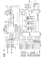
- Reference numberal 50 denotes a read-write-only IC adapted to receive a signal from a host machine, and write the information on the magnetic disc 4 by the first magnetic head 17 and the second magnetic head 20 while magnifying the minute magnetization recorded on the magnetic disc 4 and differentiating the resultant magnetization to reproduce the differentiated magnetization into digital data.
- Reference numeral 51 denotes a control IC adapted to control the stepping motor 28a, the rotation driving means 15 and various sensors by a signal from the host machine and consisting of a microcomputer or a gate array.
- the input signals from. the host machine are all signals based on the negative logic, and effective when they are in a low level.
- Reference numeral 55 denotes a motor driving 1C adapted to receive a two-phase signal, the phase of which is staggered at 90°, from the control IC 51 and drive the stepping motor 28a.
- a transistor 56 and a diode 57 are adapted to receive a signal from the control IC 51 and control the voltage to be applied to the stepping motor 28a.
- Reference numerals 58 and 59 denote inverters for transmitting a signal from the control IC 51 to the host machine, which the inverters 58 and 59 having open collector outputs, and 60 and 61 terminations used to match impedances with respect to a signal from the host machine.
- the write protection sensor 54 for preventing the writing in the magnetic disc 4 is adapted to prohibit the writing in a low level.
- the disc-in sensor 52 for indicating that the magentic disc 4 is held in the apparatus body or not is adapted to indicate in a low level that the magnetic disc 4 is held in the apparatus body.
- the track sensor 32 for indicating an initial track in the recording and reproducing region of the magnetic disc 4 is adapted to indicate in a low level that. the first magnetic head 17 and the second magnetic head 20 are positioned in the track 00.
- the control IC 51 When a low-level pulse is input into an auto eject signal with a drive select signal from the host machine and a signal from the disc-in sensor 52 in low levels, the control IC 51 ignores all input signals thereinto and retains a motor-on signal.
- the transistor 56 is then turned on the send a two-phase signal, the phase of which is staggered 90 0 , to the stepping motor-driving IC 55 to move the stepping motor 28a to the inner side of the magnetic disc 4 at about 3 ms.
- the first magnetic head 17 and the second magnetic head 20 are moved to the inner side of the recording and reproducing region of the magnetic disc 4, and the locking ' portion 44a of the engagement means 44 and the projection 23a of the connecting portion 23 engage each other in, for example, the track number 86.
- the stepping motor 28a is then further sent to a track number (track number 88 in this embodiment), which is on the inner side of the track in which the locking portion 44a and the projection 23a engage with each other, by the control IC 51.
- the engagement means 44 is thereafter raised by the projection lk of the chassis 1, and the locking portion 44a and the projection 23a disengage from each other, The automatically discharging of the magnetic dis 4 is thus completed.
- the control IC 51 is adapted to memorize the track number used before the magnetic disc 4 is automatically discharged, and can be reutrned to the track of the number after the automatically discharging of the magnetic disc 4 has been completed.
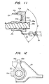
- Figs.9 to 12 show another embodiment of the connecting structure between the engagement means 44, and the connecting body 23 and the screw 28b.
- a nut 70 provides with a spherical surface 70a.
- the nut 70 contacts between the spherical surface 70a thereof and a slope section 23c of the connecting body 23 by a tension spring 39.
- a side end section of a locking portion 70b of the nut 70 always contacts with a side end section of an opening 23d of the connecting body 23, because the nut 70 moves along a spiral slope section 28e of the screw 28b by the tension of the tension spring 39.
- a projecting portion 70c of the nut 70 engages with an engagement means 80 of the ejection lever 9 so as to eject the cartridge 5 by the rotation of the stepping motor 28a.
- the engagement means 80 provided the ejection lever 9 is shown as the real line of Fig.9 in the condition that the cartridge 5 is installed with the holder 6.
- the nut 70 moves to the position shown in two-dots chain line 70" by the rotation of the screw 28b (an arrow A direction). Then the projecting portion 70c of the nut 70 engages with a ratchet 82 which is holded rotatively by a spring 81.
- the whole engagement means 80 is supported rotatively and resiliently to the ejection lever 9 and the spring 84.
- the engagement position between the projecting portion 70c of the nut 70 and the ratchet 82 is defined by the projecting portion lL provided with the chassis 1, when the cartridge 5 is inserted therein.
- the spherical surface 70a formed the nut 70 contacts centripetally with the slope 23c section, which is a taper section having an angle 6 , of the connecting body 23 by the tension of the tension spring 39, and also the spiral slope section 28e having a V-shaped groove at 300 of the screw 28b contacts concentrically with the nut 70 along the slope section 23c at 30 0 , so that the rotation angle of the screw 28b enable to give highly accurate and stable displacement for the nut 70.
- the support 27, the connecting body 23, the first head support member 18, the second head support member 21, the first magnetic head 17 and the second magnetic head 20 are difined the perpendicular position to the plane surface of the magnetic disc 4 by the guide member 26, respectively.
- a clearance 23e between the opening 23d and the locking portion 70b enable to permit the minute inclination for the screw 28b in the parallel surface to the plane surface of the magnetic disc 4.
- the dimensional accuracy tolerance which acts as a frictional resistance, hardly function to the screw 28b.
Landscapes
- Moving Of Heads (AREA)
- Feeding And Guiding Record Carriers (AREA)
Applications Claiming Priority (6)
| Application Number | Priority Date | Filing Date | Title |
|---|---|---|---|
| JP20860/85 | 1985-02-07 | ||
| JP60020860A JPS61182665A (ja) | 1985-02-07 | 1985-02-07 | 磁気記録再生装置 |
| JP60049891A JPS61208667A (ja) | 1985-03-13 | 1985-03-13 | 磁気記録再生装置 |
| JP49891/85 | 1985-03-13 | ||
| JP92835/85 | 1985-04-30 | ||
| JP60092835A JPS61250869A (ja) | 1985-04-30 | 1985-04-30 | 磁気記録再生装置 |
Publications (3)
| Publication Number | Publication Date |
|---|---|
| EP0192095A2 true EP0192095A2 (fr) | 1986-08-27 |
| EP0192095A3 EP0192095A3 (en) | 1988-10-05 |
| EP0192095B1 EP0192095B1 (fr) | 1992-01-29 |
Family
ID=27283200
Family Applications (1)
| Application Number | Title | Priority Date | Filing Date |
|---|---|---|---|
| EP86101207A Expired EP0192095B1 (fr) | 1985-02-07 | 1986-01-30 | Appareil d'enregistrement et de reproduction magnétique |
Country Status (3)
| Country | Link |
|---|---|
| US (1) | US4675756A (fr) |
| EP (1) | EP0192095B1 (fr) |
| DE (1) | DE3683655D1 (fr) |
Cited By (1)
| Publication number | Priority date | Publication date | Assignee | Title |
|---|---|---|---|---|
| EP0917141A3 (fr) * | 1997-11-14 | 2000-01-26 | Caleb Technology Corporation | Dispositif d'entrainement pour disques rotatifs amovibles |
Families Citing this family (6)
| Publication number | Priority date | Publication date | Assignee | Title |
|---|---|---|---|---|
| US4734851A (en) * | 1985-04-17 | 1988-03-29 | Dennis Director | Write protect control circuit for computer hard disc systems |
| USRE33328E (en) * | 1985-04-17 | 1990-09-11 | Write protect control circuit for computer hard disc systems | |
| US5040084A (en) * | 1989-04-06 | 1991-08-13 | Digisys Corporation | Disk drive system and method |
| TW245792B (fr) * | 1993-06-10 | 1995-04-21 | Ibm | |
| KR100452081B1 (ko) * | 1996-06-05 | 2004-11-16 | 소니 가부시끼 가이샤 | 디스크 카트리지의 로딩 장치 |
| US20110276988A1 (en) * | 2010-05-07 | 2011-11-10 | Po-Hsiang Huang | Optical disc drive |
Family Cites Families (4)
| Publication number | Priority date | Publication date | Assignee | Title |
|---|---|---|---|---|
| DE2812574C3 (de) * | 1978-03-22 | 1981-01-29 | Siemens Ag, 1000 Berlin Und 8000 Muenchen | Diskettenlaufwerk |
| JPS6042542B2 (ja) * | 1978-12-01 | 1985-09-24 | 株式会社日立製作所 | 磁気ヘッド支持装置 |
| US4450492A (en) * | 1981-10-28 | 1984-05-22 | Clarion Co., Ltd. | Interlocking gear control mechanism in magnetic tape recording/playing apparatus |
| GB2142464B (en) * | 1983-06-15 | 1986-10-15 | Alps Electric Co Ltd | Recording and reproducing apparatus for disc cartridges |
-
1986
- 1986-01-30 EP EP86101207A patent/EP0192095B1/fr not_active Expired
- 1986-01-30 DE DE8686101207T patent/DE3683655D1/de not_active Expired - Lifetime
- 1986-02-04 US US06/826,001 patent/US4675756A/en not_active Expired - Fee Related
Cited By (1)
| Publication number | Priority date | Publication date | Assignee | Title |
|---|---|---|---|---|
| EP0917141A3 (fr) * | 1997-11-14 | 2000-01-26 | Caleb Technology Corporation | Dispositif d'entrainement pour disques rotatifs amovibles |
Also Published As
| Publication number | Publication date |
|---|---|
| US4675756A (en) | 1987-06-23 |
| EP0192095A3 (en) | 1988-10-05 |
| EP0192095B1 (fr) | 1992-01-29 |
| DE3683655D1 (de) | 1992-03-12 |
Similar Documents
| Publication | Publication Date | Title |
|---|---|---|
| US20020024761A1 (en) | High-density flexible disk drive having a function of facilitating correct insertion of a large-capacity flexible disk thereinto without an insertion error | |
| US6865047B2 (en) | Single reel tape cartridge and recording and reproducing device using the tape cartridge | |
| EP0137311B1 (fr) | Dispositif pour charger ou décharger un emballage de disque magnétique | |
| JPS58224480A (ja) | デイスク駆動装置 | |
| US4146912A (en) | Disk interlock mechanism | |
| US6480360B1 (en) | Method of accessing a disk-like recording medium in a disk cartridge | |
| US5291361A (en) | Disk drive with low elevated head unloading mechanism | |
| EP0192095A2 (fr) | Appareil d'enregistrement et de reproduction magnétique | |
| US4772965A (en) | Cassette loading mechanism for a recording and/or reproducing apparatus | |
| EP0628965B1 (fr) | Appareil d'enregistrement/reproduction et cassettes pour cet appareil | |
| US4833553A (en) | Magnetic disc cartridge loading and unloading mechanism | |
| JP2658648B2 (ja) | ローディング装置 | |
| US6556373B1 (en) | Disk apparatus, method of accessing head thereof to disk-like recording medium, and method of retracting the same | |
| US6552870B2 (en) | Disk drive improved in mounting structure of a printed circuit board with respect to a motor frame | |
| US4647995A (en) | Magnetic recording and/or reproducing apparatus | |
| US4853806A (en) | Apparatus for regulating the force rendered to a magnetic disc by a magnetic head in a rotary magnetic disc device | |
| US20010033443A1 (en) | Large capacity disk drive | |
| US6807026B2 (en) | Disk drive having a structure for preventing a front shutter from coming off from a main frame | |
| JPH0462429B2 (fr) | ||
| US20010006441A1 (en) | Floppy disk drive in which an eject lever is attached to a projection formed integral with a main frame thereof | |
| JPH10144015A (ja) | フレキシブルディスクドライブ | |
| JPH09312075A (ja) | 磁気記録再生装置の持上げアーム押え装置 | |
| JP3214539B2 (ja) | 磁気記録再生装置のヘッド移送機構 | |
| JP3352451B2 (ja) | 磁気記録再生装置のヘッド移送機構 | |
| US4725906A (en) | Disk recording-reproducing device |
Legal Events
| Date | Code | Title | Description |
|---|---|---|---|
| PUAI | Public reference made under article 153(3) epc to a published international application that has entered the european phase |
Free format text: ORIGINAL CODE: 0009012 |
|
| AK | Designated contracting states |
Kind code of ref document: A2 Designated state(s): CH DE FR GB IT LI NL SE |
|
| PUAL | Search report despatched |
Free format text: ORIGINAL CODE: 0009013 |
|
| AK | Designated contracting states |
Kind code of ref document: A3 Designated state(s): CH DE FR GB IT LI NL SE |
|
| 17P | Request for examination filed |
Effective date: 19881012 |
|
| 17Q | First examination report despatched |
Effective date: 19900322 |
|
| RBV | Designated contracting states (corrected) |
Designated state(s): DE GB |
|
| GRAA | (expected) grant |
Free format text: ORIGINAL CODE: 0009210 |
|
| AK | Designated contracting states |
Kind code of ref document: B1 Designated state(s): DE GB |
|
| REF | Corresponds to: |
Ref document number: 3683655 Country of ref document: DE Date of ref document: 19920312 |
|
| PLBE | No opposition filed within time limit |
Free format text: ORIGINAL CODE: 0009261 |
|
| STAA | Information on the status of an ep patent application or granted ep patent |
Free format text: STATUS: NO OPPOSITION FILED WITHIN TIME LIMIT |
|
| 26N | No opposition filed | ||
| PGFP | Annual fee paid to national office [announced via postgrant information from national office to epo] |
Ref country code: GB Payment date: 19991229 Year of fee payment: 15 |
|
| PGFP | Annual fee paid to national office [announced via postgrant information from national office to epo] |
Ref country code: DE Payment date: 20000331 Year of fee payment: 15 |
|
| PG25 | Lapsed in a contracting state [announced via postgrant information from national office to epo] |
Ref country code: GB Free format text: LAPSE BECAUSE OF NON-PAYMENT OF DUE FEES Effective date: 20010130 |
|
| GBPC | Gb: european patent ceased through non-payment of renewal fee |
Effective date: 20010130 |
|
| PG25 | Lapsed in a contracting state [announced via postgrant information from national office to epo] |
Ref country code: DE Free format text: LAPSE BECAUSE OF NON-PAYMENT OF DUE FEES Effective date: 20011101 |