EP0192786B1 - Injecteur angiographique commandé par un processeur - Google Patents
Injecteur angiographique commandé par un processeur Download PDFInfo
- Publication number
- EP0192786B1 EP0192786B1 EP85101770A EP85101770A EP0192786B1 EP 0192786 B1 EP0192786 B1 EP 0192786B1 EP 85101770 A EP85101770 A EP 85101770A EP 85101770 A EP85101770 A EP 85101770A EP 0192786 B1 EP0192786 B1 EP 0192786B1
- Authority
- EP
- European Patent Office
- Prior art keywords
- injection
- injector device
- recited
- angiographic injector
- angiographic
- Prior art date
- Legal status (The legal status is an assumption and is not a legal conclusion. Google has not performed a legal analysis and makes no representation as to the accuracy of the status listed.)
- Expired
Links
- 238000002347 injection Methods 0.000 claims abstract description 159
- 239000007924 injection Substances 0.000 claims abstract description 159
- 229940039231 contrast media Drugs 0.000 claims abstract description 48
- 239000002872 contrast media Substances 0.000 claims abstract description 48
- 230000015654 memory Effects 0.000 claims abstract description 35
- 238000012360 testing method Methods 0.000 claims abstract description 23
- 230000002401 inhibitory effect Effects 0.000 claims abstract description 8
- 230000000694 effects Effects 0.000 claims abstract description 6
- 230000004044 response Effects 0.000 claims abstract description 6
- 230000000747 cardiac effect Effects 0.000 claims abstract description 5
- 230000006870 function Effects 0.000 claims description 15
- 238000000034 method Methods 0.000 claims description 11
- 238000012544 monitoring process Methods 0.000 claims description 11
- 239000012528 membrane Substances 0.000 claims description 7
- 238000004891 communication Methods 0.000 claims description 6
- 238000012795 verification Methods 0.000 claims description 6
- 230000009977 dual effect Effects 0.000 claims description 4
- 230000002792 vascular Effects 0.000 claims description 3
- 230000000007 visual effect Effects 0.000 claims description 2
- 238000007599 discharging Methods 0.000 claims 1
- 230000001105 regulatory effect Effects 0.000 claims 1
- 230000004043 responsiveness Effects 0.000 claims 1
- 238000012163 sequencing technique Methods 0.000 claims 1
- 230000001360 synchronised effect Effects 0.000 claims 1
- 238000012546 transfer Methods 0.000 abstract description 2
- 230000000903 blocking effect Effects 0.000 abstract 1
- 230000036039 immunity Effects 0.000 abstract 1
- 239000004020 conductor Substances 0.000 description 12
- 230000007246 mechanism Effects 0.000 description 7
- 230000008901 benefit Effects 0.000 description 5
- 238000010586 diagram Methods 0.000 description 5
- 230000000881 depressing effect Effects 0.000 description 4
- 230000005669 field effect Effects 0.000 description 3
- 239000012530 fluid Substances 0.000 description 3
- 230000006872 improvement Effects 0.000 description 3
- 230000002093 peripheral effect Effects 0.000 description 3
- 230000008569 process Effects 0.000 description 3
- 230000002441 reversible effect Effects 0.000 description 3
- 238000011109 contamination Methods 0.000 description 2
- 230000000994 depressogenic effect Effects 0.000 description 2
- 239000007788 liquid Substances 0.000 description 2
- 238000012986 modification Methods 0.000 description 2
- 230000004048 modification Effects 0.000 description 2
- 238000012545 processing Methods 0.000 description 2
- ZCYVEMRRCGMTRW-UHFFFAOYSA-N 7553-56-2 Chemical compound [I] ZCYVEMRRCGMTRW-UHFFFAOYSA-N 0.000 description 1
- XUIMIQQOPSSXEZ-UHFFFAOYSA-N Silicon Chemical compound [Si] XUIMIQQOPSSXEZ-UHFFFAOYSA-N 0.000 description 1
- 230000006978 adaptation Effects 0.000 description 1
- 230000002411 adverse Effects 0.000 description 1
- 238000002583 angiography Methods 0.000 description 1
- 230000002457 bidirectional effect Effects 0.000 description 1
- 230000005540 biological transmission Effects 0.000 description 1
- 239000008280 blood Substances 0.000 description 1
- 210000004369 blood Anatomy 0.000 description 1
- 238000006243 chemical reaction Methods 0.000 description 1
- 238000010276 construction Methods 0.000 description 1
- 238000001514 detection method Methods 0.000 description 1
- 230000003205 diastolic effect Effects 0.000 description 1
- 229910052740 iodine Inorganic materials 0.000 description 1
- 239000011630 iodine Substances 0.000 description 1
- 230000003287 optical effect Effects 0.000 description 1
- 238000003825 pressing Methods 0.000 description 1
- 230000008672 reprogramming Effects 0.000 description 1
- 238000012552 review Methods 0.000 description 1
- 229910052710 silicon Inorganic materials 0.000 description 1
- 239000010703 silicon Substances 0.000 description 1
- 239000000243 solution Substances 0.000 description 1
- 230000003068 static effect Effects 0.000 description 1
Images







Classifications
-
- A—HUMAN NECESSITIES
- A61—MEDICAL OR VETERINARY SCIENCE; HYGIENE
- A61M—DEVICES FOR INTRODUCING MEDIA INTO, OR ONTO, THE BODY; DEVICES FOR TRANSDUCING BODY MEDIA OR FOR TAKING MEDIA FROM THE BODY; DEVICES FOR PRODUCING OR ENDING SLEEP OR STUPOR
- A61M5/00—Devices for bringing media into the body in a subcutaneous, intra-vascular or intramuscular way; Accessories therefor, e.g. filling or cleaning devices, arm-rests
- A61M5/14—Infusion devices, e.g. infusing by gravity; Blood infusion; Accessories therefor
- A61M5/142—Pressure infusion, e.g. using pumps
- A61M5/145—Pressure infusion, e.g. using pumps using pressurised reservoirs, e.g. pressurised by means of pistons
- A61M5/1452—Pressure infusion, e.g. using pumps using pressurised reservoirs, e.g. pressurised by means of pistons pressurised by means of pistons
- A61M5/14546—Front-loading type injectors
-
- A—HUMAN NECESSITIES
- A61—MEDICAL OR VETERINARY SCIENCE; HYGIENE
- A61M—DEVICES FOR INTRODUCING MEDIA INTO, OR ONTO, THE BODY; DEVICES FOR TRANSDUCING BODY MEDIA OR FOR TAKING MEDIA FROM THE BODY; DEVICES FOR PRODUCING OR ENDING SLEEP OR STUPOR
- A61M5/00—Devices for bringing media into the body in a subcutaneous, intra-vascular or intramuscular way; Accessories therefor, e.g. filling or cleaning devices, arm-rests
- A61M5/007—Devices for bringing media into the body in a subcutaneous, intra-vascular or intramuscular way; Accessories therefor, e.g. filling or cleaning devices, arm-rests for contrast media
-
- A—HUMAN NECESSITIES
- A61—MEDICAL OR VETERINARY SCIENCE; HYGIENE
- A61M—DEVICES FOR INTRODUCING MEDIA INTO, OR ONTO, THE BODY; DEVICES FOR TRANSDUCING BODY MEDIA OR FOR TAKING MEDIA FROM THE BODY; DEVICES FOR PRODUCING OR ENDING SLEEP OR STUPOR
- A61M5/00—Devices for bringing media into the body in a subcutaneous, intra-vascular or intramuscular way; Accessories therefor, e.g. filling or cleaning devices, arm-rests
- A61M5/14—Infusion devices, e.g. infusing by gravity; Blood infusion; Accessories therefor
- A61M5/142—Pressure infusion, e.g. using pumps
- A61M5/145—Pressure infusion, e.g. using pumps using pressurised reservoirs, e.g. pressurised by means of pistons
- A61M5/1452—Pressure infusion, e.g. using pumps using pressurised reservoirs, e.g. pressurised by means of pistons pressurised by means of pistons
- A61M5/14566—Pressure infusion, e.g. using pumps using pressurised reservoirs, e.g. pressurised by means of pistons pressurised by means of pistons with a replaceable reservoir for receiving a piston rod of the pump
-
- A—HUMAN NECESSITIES
- A61—MEDICAL OR VETERINARY SCIENCE; HYGIENE
- A61M—DEVICES FOR INTRODUCING MEDIA INTO, OR ONTO, THE BODY; DEVICES FOR TRANSDUCING BODY MEDIA OR FOR TAKING MEDIA FROM THE BODY; DEVICES FOR PRODUCING OR ENDING SLEEP OR STUPOR
- A61M5/00—Devices for bringing media into the body in a subcutaneous, intra-vascular or intramuscular way; Accessories therefor, e.g. filling or cleaning devices, arm-rests
- A61M5/14—Infusion devices, e.g. infusing by gravity; Blood infusion; Accessories therefor
- A61M5/168—Means for controlling media flow to the body or for metering media to the body, e.g. drip meters, counters ; Monitoring media flow to the body
- A61M5/172—Means for controlling media flow to the body or for metering media to the body, e.g. drip meters, counters ; Monitoring media flow to the body electrical or electronic
-
- A—HUMAN NECESSITIES
- A61—MEDICAL OR VETERINARY SCIENCE; HYGIENE
- A61M—DEVICES FOR INTRODUCING MEDIA INTO, OR ONTO, THE BODY; DEVICES FOR TRANSDUCING BODY MEDIA OR FOR TAKING MEDIA FROM THE BODY; DEVICES FOR PRODUCING OR ENDING SLEEP OR STUPOR
- A61M2230/00—Measuring parameters of the user
- A61M2230/04—Heartbeat characteristics, e.g. ECG, blood pressure modulation
Definitions
- This invention pertains to angiographic devices for injecting into a patient contrast media at a controlled rate and pressure during x-ray photography. More specifically, this invention is an improvement over US 4 006 736, which improvement concerns automated control of such angiographic injector devices being responsive to input information supplied by an operator to develop control signals for automatically controlling the injection process.
- An angiographic injector device according to the preamble part of claim 1 is known from US 4 006 736.
- An angiographic injector is useful for controlling the delivery rate, amount, duration, and pressure of contrast media, usually a liquid iodine solution, injected into a patient.
- contrast media usually a liquid iodine solution
- Such devices are used in x-ray photography to enhance the contrast of the image obtained thereby.
- an operator loads the same with a certain amount of contrast media, connects a delivery tube extending from a fluid reservoir of the device to a catheter placed in the vascular system of a patient, and then actuates the device by forcing the media into the blood stream while exposing the patient to x-rays during the photographic process.
- the contrast media is injected, for example, in step-wise changing flow rates and/or pressures. It is also desirable to provide multiphasic injections in which the programmed injection profile is delivered several times in succession under operator or remote control. Also, it may be desirable to automatically compute parameters involved in the injection of a specific amount of contrast media and to enable the size of the syringe to be changed without adversely affecting the operation of the injection and without requiring reprogramming. Such features are not known to exist with prior art devices. Moreover, certain mechanical control and electronic control features can be integrated to enhance reliability, such as by providing a mechanical stop member to prevent further movement of a syringe plunger when a predeter- . mined amount of contrast media already has been injected.
- the device according to the invention is able to provide safety and/or control features which limit the injection pressure and/or delivery of contrast media when ceratin limits are exceeded, such as a pressure limit of contrast media in the syringe.
- the invention is also able to provide a mechanical stop mechanism for mechanically preventing the plunger of a syringe from further movement when a given amount of contrast media has been injected, wherein the stop position is automatically determined on the basis of injection information supplied to the device.
- the invention is furthermore able to provide a multi-level injection sequence under processor control whereby the duration and/or injection rate and/or pressure may step-wise be changed during separate injection sequences, as well as to provide means for compensating the plunger drive rate and delivered pressure on the basis of syringe size during the injection process.
- the present invention provides pre- programmed injection parameters stored in a memory which may conveniently be recalled instantly and to provide means for retaining the stored parameters in the memory in the event of power interruption to the device.
- Another advantage of the present invention is to provide a plurality of reliability features, such as parameter verification, self-calibration, and self-testing of the various components of the device in order to improve safety.
- a yet further feature of the present invention is to provide means for providing messages from the angiographic injector to the operation, in human readable format.
- the invention comprises a processor-controlled angiographic injector device including a pressure jacket for receiving a syringe containing liquid contrast media, contrast media drive means for forcing the media from the syringe, and processor control system for calculating injection control signals and for controlling the delivery of the contrast media.
- the processor control system is programmed to elicit injection parameters from an operator or from a pre-programmed storage module and, on the basis of the injection parameters, for calculating the necessary control signals for a closed-loop servo system which actuates the plunger of a syringe.
- the processor also determines position limits of plunger actuation and effects actuation of a mechanical stop member to block further movement of the plunger when a predetermined volume of media is injected. To improve reliability, actuation of motors for the mechanical stop member and the plunger drive are alternately enabled by a safety relay.
- a preprogrammed storage module for storing routine injection parameters so that they can be instantly recalled.
- a hardware verification system comprising primary and secondary memories for storing duplicates of injection parameters also is provided.
- the controller additionally provides multi-phasic injection sequences which involve step-wise changing of the injection parameters (e.g., rate, duration, and/ or pressure) during an injection sequence.
- the angiographic injector device includes a watchdog circuit which monitors failures in the processor-controlled system, such as in the memories, and the processor itself, and in response to a failure, inhibits the plunger drive means.
- a self-check feature periodically performs diagnostic routines and a self-calibration feature re-calibrates the servo positioning system when there is a deviation from desired accuracy.
- an alternative embodiment of the device includes means for monitoring an ECG waveform and for injecting a small bolus of contrast media at a given rate and pressure during the diastolic interval.
- the alternative embodiment includes an interface circuit for providing external digital communication for transferring either status and/or control information (e.g. injection.parameters).
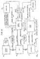
- a central processing unit (CPU) 10 such as a commercially known Z80A microprocessor which includes a memory.
- the memory comprises a read only portion (ROM) such as a 2732 EPROM and a random access portion (RAM) such as a 4016 static NMOS RAM coupled to the CPU 10 is an I/O module 12 which, under control the CPU 10, prompts the operator for certain input parameters and also alerts the operator of error conditions in the system.
- the I/O module is composed of peripheral devices such as the Zilog Z80-PIO peripheral input/output controller.
- An indicator panel 14, and keyboard 16 provides operator/ injector device interface.
- the panel 14 includes a flat sealed membrane to shield electrical switch contacts from contamination.
- a storage module 18 stores pre-programmed injection parameters which may be instantly recalled and supplied to the CPU 10 when a routine injection procedure is to be performed.
- the injection module 18 comprises two primary random access memories. Each memory contains a duplicate of the information of the other memory, and prior to an injection procedure, the contents thereof are compared for consistency. If inconsistent, the injection is inhibited.
- a computer interface 20 provides external remote communication with the automated injector device and functions to transfer both status information and control information with the device for remote operation and/or monitoring to provide communication compatibility with various external devices.
- the interface 20 includes, but is not limited to, a standard universal asynchronous receive/transmit port connectible by way of a commercially known RS-232 serial channel or other parallel interface.
- the contrast media to be injected into the patient is normally contained in a syringe, the plunger thereof being actuated to force the media therefrom into the vascular system of a patient through a catheter.
- the delivery rate and volume are normally derived from position signals indicative of the plunger position.
- Pressure is derived from current supplied to the motor.
- a servo control network 22 applies a conventional error signal to a servo system for controlling the position of the syringe plunger to control the flow rate and pressure of the contrast media. More specifically, the servo control network 22 supplies error signals to a servo amplifier 24 which energizes a conventional D.C. motor for controlling the position of the plunger.
- a mechanical stop controller 26 which, under the control of the CPU 10 and an interlock safety relay 28, automatically positions a mechanical stop member (subsequently described) under control of the CPU 10 to mechanically stop further plunger movement thus preventing additional injection after the desired volume of contrast media has been injected.
- the safety relay 28 alternately enables the mechanical stop motor and the plunger motor so that one and only one may be operative at a given time. This feature enhances reliability because it ensures that the mechanical stop fully reaches its appropriate position before it is possible to drive of the syringe plunger.
- a watchdog circuit 30 monitors certain functions of the CPU 10 to effect shutdown of the system by inhibiting delivery of contrast media in the event of a failure or a fault.
- the watchdog circuit as shown in Figure 1B, consists of a retriggerable timer (such as a 74123 monostable multivibrator) which generates a pulse after a fixed time interval unless a strobe signal is received from a data selector 13 before the interval elapses.
- the CPU 10 executes its control sequence and periodically outputs an address to the data selector 13 (such as 74154) which generates the strobe signal.
- NMI non-maskable interrupt
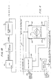
- FIG 2 depicts the servo amplifier 24 of Figure 1A.
- the servo amplifier provides power to move a drive plunger motor 40 under control of digital commands from the CPU 10.
- the servo amplifier 24 drives a plunger motor 40 which is driven by filtered direct current derived from a series of pulse width modulated current pulses.
- a D.C. voltage source 42 supplies current to the motor 40 by feeding the respective collectors of transistors 46 and 56.
- a position error detect circuit 50 switches on transistor 46 and a pulse-width modulating control circuit 52 delivers a series of enabling pulses to the field effect transistor (FET) 48.
- FET field effect transistor
- the error detect circuit 50 generates follows a position error signal from the servo control 22 via a conductor 54. During forward driving of the plunger motor 40, a corresponding set of transistors 56 and 58 is switched off. This allows d.c. current pulses to flow in a forward direction through the plunger motor 40.
- the error detect circuit 50 switches on transistor 56 and the pulse width modulating circuit 52 pulses the field effect transistor 58. In this fashion, the plunger motor 40 is driven in the reverse dierction by the supply of d.c. current pulses in an opposite direction therethrough.
- FETs 48 and 58 a set of silicon controlled rectilius also can be used.
- the position error signal supplied to the servo amplifier 24 over the conductor 54 indicates whether the plunger is ahead of or behind the desired position, and also controls the drive transistors 46, 56, 48 and 58 in an appropriate fashion to that the plunger motor 40 causes the plunger (not shown) of the syringe to track the desired position to maintain the appropriate flow rate, pressure and/or duration.
- the position error signal is proportional to the magnitude of the difference between the actual position of the plunger and the desired position of the plunger. As the difference increases, so does the width of the drive pulses supplied by the pulse-width modulating circuit 52 to the drive transistors 58 and 48. Thus, when the position error signal is large, the average current supplied to the plunger motor also increases.
- the servo amplifier 24 also includes a pressure limit circuit 60 which functions to inhibit the pulse-width modulating circuit 52 and shut down the drive current pulses supplied to the plunger motor 40.
- the circuit 60 constitutes a control circuit which informs the servo control when the pressure in the syringe exceeds a given set point established by the processor 10. It does so by monitoring motor current which is proportional to the fluid .pressure, and operates to reduce the motor velocity of the plunger motor 40 by cutting the duty cycle of pulse-width modulated current pulses when the pressure exceeds a preset limit.
- the injectof device has pressure input means to set and/or display the pressure limit in conventional units of PSI, KPA, KG or ATU. A switch is also provided to select and/or display the selected unit.
- the servo amplifier 24 causes the 'plunger position to follow the position command established by the processor 10.
- a digital-to-analog converter device 74 in the servo control portion of the system sets the pressure limit command.
- the pressure limit circuit 60 asserts a pressure limit indication signal 64 which informs the CPU 10 to stop changing the position command signal.
- the pressure limit command signal is supplied to the servo amplifier 24 via conductor 62.
- the CPU 10 retakes control by resuming the transmission of position command signals starting from the known plunger position.
- the plunger position derived from a rotary potentiometer or optical encoder, is monitored by a plunger position circuit 66, also embodied in the servo amplifier 24.
- the output of the plunger position circuit 66 is supplied to the servo control 22 via a conductor 68.
- FIG. 3 depicts a servo control circuit 22 in greater detail.
- the servo control circuit 22 provides an interface between the digital and analog components of the angiographic device.
- the CPU 10 provides digital position command signals via conductor 70 to a driver bidirectional buffer 72.
- the digital position command signals are eventually converted to an analog signal by a digital-to-analog converter 74 which are compared by a comparison network in the error circuit 76 which then appears as position error signal on conductor 54.
- the plunger position error signal on conductor 54 is supplied to the servo amplifier 24 of Fig. 2.
- an analog multiplexer 75 under control of the CPU 10 or a clocking signal, selectively conveys analog output signals from the control D/A circuit 74 or error circuit 76 to an A/D converter 77.
- the A/D converter 77 converts these signals to digital form and then, in turn, passes it to the CPU 10.
- the CPU 10 uses these digital signals to perform such functions as calibration, self-testing, and servo control. These functions are subsequently described.
- the servo control circuit 22 also regulates the operation of the interlocked mechanical stop/ plunger relay in the servo amplifier circuit 24 and the mechanical stop controller circuit 26.
- a peripheral input/output device 78 in the servo control circuit 22 provides means for transferring status and control signals to alter the operation of the servo amplifier circuit 24 and the mechanical stop controller 26.
- the input/output circuit 78 removes the plunger ARM signal via conductor 80 when the plunger reaches a predetermined position as determined by the CPU 10 and monitored by the plunger position circuit 66 ( Figure 2).
- An ARM signal supplied over the conductor 80 is conveyed to the mechanical stop controller circuit 26 to actuate a mechanical stop drive motor which inhibits further plunger movement. This feature also will be subsequently described.
- the servo control circuit 22 also generates pressure command signals and monitors the pressure limit.
- Figure 4 depicts the mechanical stop controller 26 wherein a mechanical stop motor 90 couples a mechanical stop member to actuate it against the plunger drive mechanism to block movements thereof when a predetermined calculated volume of contrast media has been injected.
- the mechanical stop motor 90 turns a ball screw to drive a mechanical stop plate forward.
- the drive command is given to drive the mechanical stop motor 90 at full speed until the mechanical stop position indicator on the mechanical stop mechanism indicates that desired position has been attained. This is accomplished by converting a potentiometer position signal supplied over conductor 111 from the stop mechanism to a digital value via an analog/digital converter. When the position signal indicates engagement of the stop plate, the drive command is removed.
- Figure 5A depicts an illustrative mechanical assembly for driving the piston of a syringe containing contrast media.
- a movable drive plate 200 actuates a piston 202 of a syringe 204 by way of a shaft 206.
- the piston 202 connects to a spring clip 208 when engaged therewith.
- the spring clip 208 is fastened to the end of the shaft 206.
- a plunger drive motor (not shown) corresponding to the motor 40 (Fig. 4) of the controller actuates the shaft 206 through the plunger plate 200. Linear movement of the plunger plate is guided by a guide rod 210.
- a mechanical stop prevents further movement of the drive shaft when a fixed amount of contrast media has been injected.
- a stop member in the form of a plate 212 is prepositioned prior to an injection. Prepositioning is done by a stop motor 214 (corresponding to motor 90 of Fig. 4) under control of the CPU 10.
- Conventional position transducers in the form of resistive potentiometers supply position information of the stop member 212 to the CPU 10 through an A/D converter.
- Actuation of the stop member 212 is done by rotation of shaft 216 having threads mechanically coupled to a bore that is journalled through a bushing 218 held against the stop plate 212 by a nut 220.
- motor 214 When energized, turns a grooved, flexible drive belt 222, which in turn, rotates a drive pulley 224.
- the pulley 224 connects to the shaft 216.
- Figure 5B depicts a system for visually indicating the volume of contrast media injected from a syringe by utilizing different scales.
- Each scale corresponds to a syringe of a particular size, and the "active" scale is indicated by the appropriate light being energized.
- a face card 226 contains three separate scales 228, 230, and 232 of different units corresponding to incremental units of media in a syringe 204. Syringes of different diameters yield different units of media for the same linear movement of the plunger 202.
- LED indicators 234, 236 and 238 are provided to visually indicate which unit applies to a particular syringe.
- One of these indicators is activated by a switch to show which scale is active, in which case, a needle 240 carried by arm 242 indicates relative volume injected.
- the arm 242 connects to the stop plate 212 while the face card 226 connects to the drive plate 200.
- the double-throw, double-pole operation of the relay 28 energizes either the drive motor 90 (Fig. 4) or the plunger drive motor 40, but not both simultaneously.
- the mechanical stop motor 90 functions similarly to the plunger motor 40 of Figure 2, in that it includes a set of field effect transistors 100, 102, 104 and 106 which are energized to drive the mechanical stop motor 90 in a forward and/or reverse direction.
- Direction is controlled by a direction circuit 109 in response to a signal from the servo control 22 supplied via the conductor 108.
- the mechanical limit of the mechanical stop motor is controlled by a mechanical stop position circuit 110 which responds to a limit switch when the stop plate reaches a forward-most position or rearward-most position.
- the CPU 10 controls the system using a microprocessor and associated program for monitoring or eliciting input information (e.g. injection parameters) supplied by an operator and then develops command information to control the injector device.
- the CPU 10 communicates with the I/0 module 12 which interfaces external switches on the front control panel of the system.
- the watchdog circuit 30 implements an active system for inhibiting injection of contrast media in the event of a microprocessor failure.
- the circuit 30 includes a re-settable timer which opens the safety relay 44 after a predetermined time period unless the CPU 10 actively resets it, thus allowing this cycle to repeat. Thus, if the CPU 10 fails, the safety relay 44 will be deactivated without further operation of the CPU 10.
- the I/O module 12 monitors a manual signal supplied by the operator via a manual start switch 12 or an event signal from an external device supplied over the conductor 114.
- the automated angiographic injector device may respond to certain cardiac events by monitoring an ECG signal thereby to actuate, or start an injection, at a predetermined time instance during an ECG cycle. This is done using well known techniques by the external event signal, and is particularly useful during certain cardiac studies.
- the control/display panel 14 provides user/ device interface for inputting and displaying injection parameters, such as syringe size, flow rate, volume, duration, pressure limit, or rise/fall time. This information can be prompted by the CPU 10 and entered by the operator. The entries are echoed back to the operator for a visual verification on a display of the panel 14.
- the panel 14 comprises a sealed membrane switch panel that is impervious to fluid spills and wipes clean without damage to switches contained underneath.
- the injection parameters Prior to an injection, the injection parameters are displayed and verified by an operator. Verification enables, e.g. arms, the injector device, and is preferably accomplished manually by depressing a contact switch associated with each injection parameter. After an injection, the actual values of flow, volume, etc. can be displayed so that the operator may confirm an effective or safe injection.
- a pre-programmed injection module 18 provides non-volatile storage of injection parameters. Specific routine angiographic procedures require established flow rates, volumes, pressures and linear rise/fall time, but once these parameters are established, set-up of the angiographic device becomes routine. As an added convenience, these parameters can be stored in the pre-programmed injection module 18 so that an injection can proceed immediately after arming the system without the necessity to re-enter the injection parameters. To enhance reliability of the pre-programmed injection module 18, the stored injection parameters are verified by duplicating the values thereof in an auxiliary memory.
- the pre-programmed injection module preferably comprises a primary and a secondary random access memory for storing duplicates of the injection parameters and, prior to an injection procedure, the CPU 10 compares the contents of both memories to verify the parameters. Both memories are maintained with batteries when power is shut down thereby achieving non-volatility.
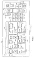
- Figure 6 depicts a preferred arrangement of the front panel 14 of Figure 1 for providing an indication of injection parameters entered, confirmed and/or displayed in the device, and for providing an indication of control/injection parameters under which an injection had taken place.
- the front panel 14 preferably comprises a flat, sealed membrane covering switches located beneath the flexible membrane. This structure seals the switches from possible contamination from an external environment.
- the front panel 14 includes various sections to facilitate entry of injection parameters and for displaying the status of an injector procedure. Display and entry of information is preferably accomplished in human readable format.
- the front panel 14 includes a sentinel 130 which includes an alphanumeric display section 132.
- the display section 132 displays, among. others, alphabetical and numeric information which is entered into the injector device by way of an alphanumeric keypad section 134.
- the keypad 134 enables entry of both numeric and character information in a conventional manner. During entry, the information is displayed on the sentinel display section 132.
- the front panel also includes a dual function control and display section including an individual input pad 142 for entering and/or confirming, among other parameters, a rise/fall time of flow of contrast media.
- a dual function control and display section including an individual input pad 142 for entering and/or confirming, among other parameters, a rise/fall time of flow of contrast media.
- the switch pad 144 is depressed and the desired rise/ fall injection parameter is entered into the device, the specific rise/fall injection parameter is displayed in the display section 146.
- a desired flow rate also can be programmed into the injection device. This injection parameter is displayed in a flow rate display 148 and entered into the device by switch input pad 150.
- the units of flow rate can be entered or displayed in milliliters per second milliliters per minute, or milliliters per hour under control of a switch pad 152.
- the duration of an injection can be entered by depressing the switch pad 154 and then pressing "number" keys on keypad 134. Injection duration is displayed in a display portion 156. Any two of the three parameters, flow, volume, duration, may be entered in any order, and the third then automatically is calculated.
- the volume of contrast media to be injected during an injection sequence is displayed in display 158 and is entered and/or confirmed by the switch pad 160.
- the pressure at which the contrast media is to be injected is displayed and/or entered, respectively, by display 162 and switch pad 164.
- x-ray photo delay from the time an injection sequence begins is displayed on display 166 and is entered with switch pad 168 and numerical keypad 134.
- the CPU 10 effects flashing of indicator lights located above the switch pads 144, 150, 152, 154, 160,164 and 168. For example, when the CPU 10 prompts the operator to enter the rise/fall injection parameter, an indicator light above the switch pad 144 flashes. When the appropriate value has been entered and is displayed correctly in the display 146, the switch pad 150 is depressed by the operator, whereupon display 146 ceases to flash and stays lit, while the indicator light over the switch pad 150 begins flashing. The flashing sequence advances to the next injection parameter to be entered as each parameter is entered.
- the CPU 10 effects generation of an alarm, such as an audible beep and/or error message on display 132. Further, the CPU 10 will prevent further entry or arming of the device until the error has been corrected. As an example, entry of an injection volume that is greater than the syringe size will cause an error.
- the panel 14 also has a contact switch for clearing the contents of any parameter or information displayed or entered into the injector device.
- the front panel 14 further includes an arming section 170 for selecting a single phase or a multi-phase injection sequence.
- a program section 172 is provided in order to recall routine injection parameters or to store a set of injection parameters.
- an identification tag can be generated by way of the keypad 134, displayed in the sentinel 132, and stored in non-volatile memory by depressing the store switch 174.
- One or more numbers or words, or alphanumeric combinations can be used to identify a prestored set of injection parameters.
- the set of injection parameters then is stored in a storage module under the name or number which appears in the sentinel 132 when stored. That same information can be quickly recalled by entering the name or number associated with the previously stored set of injection parameters by depressing recall switch 176.
- the operator is required to depress each of the switch pads 144, 150, 152, 154,160,164 and 168, to verify the accuracy of the injection parameters being displayed.
- a number of injections may be performed without disarming the machine after delivery of the programmed injection volume.
- Each depression of the main start switch 112 will deliver the same volume until insufficient volume remains in the syringe.
- a switch pad 178 in the arming section activates the device for a multi-phasic injection sequence.
- a level control section 182 indicates the number of levels in a single phase or multi- phasic injection sequence. The specific level may be incremented or decremented by way of switch pads 184 and 186 and parameters for each level are entered on switch pads 144, 150, 152, 154, 160,164, and 168.
- the rise/fall time, flow rate, volume, and pressure for each level are delivered until all levels (up to 9) are completed or the injection is terminated.
- all levels are delivered in continuous sequence unit the injection is complete.
- the central processing unit 10 also provides a self-calibration and a self test feature. Self-calibration allows proper servicing of critical analog/ digital and digital/analog converters in the system. Upon calling up of appropriate software routines, the processor commands a digital/ analog converter 74 to transmit a corresponding analog value, which is then switched through an appropriate analog/digital converter 74. The converted value is then compared with the original digital value thereby to allow adjustment of gain and offsets in the servo control system.
- the injector allows the user to enter a syringe size which is used to automatically adjust internal machine parameters to deliver the programmed flows, volumes, and pressures.
- Syringe size entry is made by answering questions posed by the sentinel display 132 although automatic detection of size may be accomplished by means of mechanical switches located behind the turret assembly.
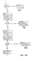
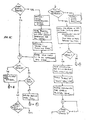
- a self-test feature of the invention embodies software routines executed by the central processor 10 which initiates checks of the electrical components, such as the memory, address and data busses, device decoding and checks the accuracy of the data conversion hardware. These functions are accomplished by conventional hardware and specialized software routines, the latter being described in the flow charts of Figures 7A, 7B, 7C and 7D. If failures are detected by CPU 10, an appropriate diagnostic message appears on sentinel display 132 to aid in repairing the machine.
- FIGS 8A, 8B, 8C and 8D are flow diagrams showing the general operational sequence of the automated injector device for performing an injection as described above.
- the data acquisition modules essentially comprises analog-to-digital and digital-to-analog converters, but are not limited to the same. These may be substituted by other types of data acquisition units to obtain information to provide the control of duration, flow rate and pressure of contrast media.
- a closed-loop servo control system is shown, but the invention may be practiced with other types of control systems. Accordingly, it is the intent of each inventor to include all such modifications as may come within the true scope of the invention which is defined by the appended claims.
Landscapes
- Health & Medical Sciences (AREA)
- Vascular Medicine (AREA)
- Engineering & Computer Science (AREA)
- Anesthesiology (AREA)
- Biomedical Technology (AREA)
- Heart & Thoracic Surgery (AREA)
- Hematology (AREA)
- Life Sciences & Earth Sciences (AREA)
- Animal Behavior & Ethology (AREA)
- General Health & Medical Sciences (AREA)
- Public Health (AREA)
- Veterinary Medicine (AREA)
- Infusion, Injection, And Reservoir Apparatuses (AREA)
- Fuel-Injection Apparatus (AREA)
- Apparatus For Radiation Diagnosis (AREA)
- Electrotherapy Devices (AREA)
Claims (55)
Priority Applications (3)
| Application Number | Priority Date | Filing Date | Title |
|---|---|---|---|
| DE8585101770T DE3575862D1 (de) | 1985-02-18 | 1985-02-18 | Angiographischer injektor mit einer steuereinheit. |
| EP85101770A EP0192786B1 (fr) | 1985-02-18 | 1985-02-18 | Injecteur angiographique commandé par un processeur |
| AT85101770T ATE50146T1 (de) | 1985-02-18 | 1985-02-18 | Angiographischer injektor mit einer steuereinheit. |
Applications Claiming Priority (1)
| Application Number | Priority Date | Filing Date | Title |
|---|---|---|---|
| EP85101770A EP0192786B1 (fr) | 1985-02-18 | 1985-02-18 | Injecteur angiographique commandé par un processeur |
Publications (3)
| Publication Number | Publication Date |
|---|---|
| EP0192786A2 EP0192786A2 (fr) | 1986-09-03 |
| EP0192786A3 EP0192786A3 (en) | 1986-10-29 |
| EP0192786B1 true EP0192786B1 (fr) | 1990-02-07 |
Family
ID=8193310
Family Applications (1)
| Application Number | Title | Priority Date | Filing Date |
|---|---|---|---|
| EP85101770A Expired EP0192786B1 (fr) | 1985-02-18 | 1985-02-18 | Injecteur angiographique commandé par un processeur |
Country Status (3)
| Country | Link |
|---|---|
| EP (1) | EP0192786B1 (fr) |
| AT (1) | ATE50146T1 (fr) |
| DE (1) | DE3575862D1 (fr) |
Cited By (6)
| Publication number | Priority date | Publication date | Assignee | Title |
|---|---|---|---|---|
| US7860583B2 (en) | 2004-08-25 | 2010-12-28 | Carefusion 303, Inc. | System and method for dynamically adjusting patient therapy |
| US8038593B2 (en) | 2003-12-05 | 2011-10-18 | Carefusion 303, Inc. | System and method for network monitoring of multiple medical devices |
| US8251071B2 (en) | 2004-10-13 | 2012-08-28 | Mallinckrodt Llc | Powerhead of a power injection system |
| US9069887B2 (en) | 2000-05-18 | 2015-06-30 | Carefusion 303, Inc. | Patient-specific medication management system |
| US9427520B2 (en) | 2005-02-11 | 2016-08-30 | Carefusion 303, Inc. | Management of pending medication orders |
| US9600633B2 (en) | 2000-05-18 | 2017-03-21 | Carefusion 303, Inc. | Distributed remote asset and medication management drug delivery system |
Families Citing this family (43)
| Publication number | Priority date | Publication date | Assignee | Title |
|---|---|---|---|---|
| CA1274737A (fr) * | 1985-08-08 | 1990-10-02 | Joanna Schoon | Methode et appareil de perfusion automatique dans les cycles d'alimentation parenterale totale |
| FR2638364A1 (fr) * | 1988-10-27 | 1990-05-04 | Farcot Jean Christian | Appareillage pour la realisation d'une angioplastie prolongee |
| EP0503670B1 (fr) * | 1991-03-14 | 1996-05-22 | Sharp Kabushiki Kaisha | Pompe d'infusion intraveineuse peristaltique capable d'afficher le nom de l'application sélectionnée |
| US6397098B1 (en) | 1994-09-21 | 2002-05-28 | Medrad, Inc. | Data communication and control for medical imaging systems |
| US5800387A (en) * | 1996-10-04 | 1998-09-01 | Alaris Medical Systems, Inc. | Safety monitoring apparatus for a patient care system |
| DE19644622C2 (de) * | 1996-10-18 | 1999-10-28 | Schering Ag | Medizinische, vorgefüllte, sterilisierte Spritze |
| EP0935476A1 (fr) | 1996-10-18 | 1999-08-18 | Schering Aktiengesellschaft | Seringue avec bouchon en polyethylene |
| FR2757772B1 (fr) * | 1996-12-31 | 1999-03-26 | Karcher Gilles | Injecteur a telecommande pour interventions medicales |
| US6339718B1 (en) | 1999-07-30 | 2002-01-15 | Medrad, Inc. | Programmable injector control |
| DE19947907A1 (de) * | 1999-10-06 | 2001-04-19 | Thomas Wolffgram | Katheter für die kombinierte Untersuchung des linken Ventrikels sowie der rechten und der linken Koronararterien |
| US9741001B2 (en) | 2000-05-18 | 2017-08-22 | Carefusion 303, Inc. | Predictive medication safety |
| US10062457B2 (en) | 2012-07-26 | 2018-08-28 | Carefusion 303, Inc. | Predictive notifications for adverse patient events |
| US10353856B2 (en) | 2011-03-17 | 2019-07-16 | Carefusion 303, Inc. | Scalable communication system |
| US11087873B2 (en) | 2000-05-18 | 2021-08-10 | Carefusion 303, Inc. | Context-aware healthcare notification system |
| US6985870B2 (en) | 2002-01-11 | 2006-01-10 | Baxter International Inc. | Medication delivery system |
| US7491191B2 (en) | 2004-02-13 | 2009-02-17 | Liebel-Flarsheim Company | Keep vein open method and injector with keep vein open function |
| US8900187B2 (en) | 2004-10-13 | 2014-12-02 | Mallinckrodt Llc | Powerhead control in a power injection system |
| US20060079842A1 (en) * | 2004-10-13 | 2006-04-13 | Liebel-Flarsheim Company | Powerhead control in a power injection system |
| EP1812101A4 (fr) | 2004-11-16 | 2014-04-23 | Medrad Inc | Modelage de propagation pharmaceutique |
| DK2902053T3 (da) | 2004-11-24 | 2017-11-13 | Bayer Healthcare Llc | Anordninger, systemer og fremgangsmåder til væskefremføring |
| KR101373220B1 (ko) * | 2005-09-14 | 2014-03-11 | 어시스트 메디칼 시스템즈, 인크. | 의료용 유체 주입 시스템 |
| EP2097835B1 (fr) | 2006-12-29 | 2018-05-30 | Bayer Healthcare LLC | Systèmes de génération de paramètres sur la base d'un patient pour des procédures médicales d'injection |
| EP2170165B1 (fr) | 2007-07-17 | 2018-12-05 | Bayer Healthcare LLC | Systèmes pour déterminer des paramètres pour une procédure, pour estimer une fonction cardiopulmonaire et pour une administration de fluide |
| US9421330B2 (en) | 2008-11-03 | 2016-08-23 | Bayer Healthcare Llc | Mitigation of contrast-induced nephropathy |
| CA2803169C (fr) | 2010-06-24 | 2020-09-22 | Medrad, Inc. | Modelisation de propagation pharmaceutique et de generation de parametres pour protocoles d'injection |
| HUE056182T2 (hu) | 2012-05-14 | 2022-01-28 | Bayer Healthcare Llc | Összeállítások és eljárások gyógyászati fluidum befecskendezési protokollok röntgencsõ-feszültség alapján történõ meghatározására |
| WO2014190200A1 (fr) | 2013-05-22 | 2014-11-27 | Carefusion 303, Inc. | Gestion de flux de médicaments |
| US11182728B2 (en) | 2013-01-30 | 2021-11-23 | Carefusion 303, Inc. | Medication workflow management |
| US10430554B2 (en) | 2013-05-23 | 2019-10-01 | Carefusion 303, Inc. | Medication preparation queue |
| ES2831801T3 (es) | 2013-03-13 | 2021-06-09 | Carefusion 303 Inc | Sistema de gestión de medicaciones específicas para el paciente |
| US9555379B2 (en) | 2013-03-13 | 2017-01-31 | Bayer Healthcare Llc | Fluid path set with turbulent mixing chamber, backflow compensator |
| CN114267429A (zh) | 2013-03-13 | 2022-04-01 | 康尔福盛303公司 | 预测性用药安全 |
| EP3423130B1 (fr) | 2016-03-03 | 2025-05-14 | Bayer Healthcare LLC | Système et procédé d'amélioration de l'administration de liquides dans des systèmes injecteurs de plusieurs liquides |
| EP3538182A1 (fr) | 2016-11-14 | 2019-09-18 | Bayer Healthcare LLC | Procédés et systèmes de vérification du contenu d'une seringue utilisée pour l'administration de fluide médical |
| JP7493337B2 (ja) | 2017-08-31 | 2024-05-31 | バイエル・ヘルスケア・エルエルシー | 流体インジェクタシステムにおける動的圧力制御のための方法 |
| CN110891630B (zh) | 2017-08-31 | 2022-04-26 | 拜耳医药保健有限公司 | 驱动构件定位和流体注入器系统机械校准的系统和方法 |
| AU2018323442B2 (en) | 2017-08-31 | 2024-06-27 | Bayer Healthcare Llc | Fluid path impedance assessment for improving fluid delivery performance |
| AU2018326485B2 (en) | 2017-08-31 | 2024-01-04 | Bayer Healthcare Llc | Injector pressure calibration system and method |
| CN110809482B (zh) | 2017-08-31 | 2023-03-07 | 拜耳医药保健有限公司 | 流体注入器系统体积补偿系统和方法 |
| CN107991038B (zh) * | 2017-12-30 | 2023-11-10 | 四川省广元市康康医疗器械有限公司 | 一种高压注射器极限测试仪和高压注射器极限测试方法 |
| CA3097557A1 (fr) | 2018-04-19 | 2019-10-24 | Bayer Healthcare Llc | Systeme et procede de detection d'air dans un injecteur de fluide |
| CA3110859A1 (fr) | 2018-08-28 | 2020-03-05 | Bayer Healthcare Llc | Systeme d'injection de liquide, procede de prevention du reflux de liquide, et progiciel informatique |
| JP2021536278A (ja) | 2018-08-28 | 2021-12-27 | バイエル・ヘルスケア・エルエルシーBayer HealthCare LLC | 比性能を改善した流体注入器システム |
Family Cites Families (4)
| Publication number | Priority date | Publication date | Assignee | Title |
|---|---|---|---|---|
| US4006736A (en) * | 1974-11-27 | 1977-02-08 | Medrad, Inc. | Angiographic injector |
| US4273122A (en) * | 1976-11-12 | 1981-06-16 | Whitney Douglass G | Self contained powered injection system |
| IL55980A (en) * | 1977-12-02 | 1982-04-30 | Baxter Travenol Lab | Flow metering apparatus for a fluid infusion system |
| US4470758A (en) * | 1981-11-12 | 1984-09-11 | Oximetrix, Inc. | Intravenous fluid pump monitor |
-
1985
- 1985-02-18 AT AT85101770T patent/ATE50146T1/de not_active IP Right Cessation
- 1985-02-18 EP EP85101770A patent/EP0192786B1/fr not_active Expired
- 1985-02-18 DE DE8585101770T patent/DE3575862D1/de not_active Expired - Lifetime
Cited By (10)
| Publication number | Priority date | Publication date | Assignee | Title |
|---|---|---|---|---|
| US9069887B2 (en) | 2000-05-18 | 2015-06-30 | Carefusion 303, Inc. | Patient-specific medication management system |
| US9600633B2 (en) | 2000-05-18 | 2017-03-21 | Carefusion 303, Inc. | Distributed remote asset and medication management drug delivery system |
| US8038593B2 (en) | 2003-12-05 | 2011-10-18 | Carefusion 303, Inc. | System and method for network monitoring of multiple medical devices |
| US7860583B2 (en) | 2004-08-25 | 2010-12-28 | Carefusion 303, Inc. | System and method for dynamically adjusting patient therapy |
| US8340792B2 (en) | 2004-08-25 | 2012-12-25 | Carefusion 303, Inc. | System and method for dynamically adjusting patient therapy |
| US8630722B2 (en) | 2004-08-25 | 2014-01-14 | Carefusion 303, Inc. | System and method for dynamically adjusting patient therapy |
| US8251071B2 (en) | 2004-10-13 | 2012-08-28 | Mallinckrodt Llc | Powerhead of a power injection system |
| US8726910B2 (en) | 2004-10-13 | 2014-05-20 | Mallinckrodt Llc | Powerhead of a power injection system |
| US9168335B2 (en) | 2004-10-13 | 2015-10-27 | Mallinckrodt Llc | Powerhead of a power injection system |
| US9427520B2 (en) | 2005-02-11 | 2016-08-30 | Carefusion 303, Inc. | Management of pending medication orders |
Also Published As
| Publication number | Publication date |
|---|---|
| ATE50146T1 (de) | 1990-02-15 |
| DE3575862D1 (de) | 1990-03-15 |
| EP0192786A2 (fr) | 1986-09-03 |
| EP0192786A3 (en) | 1986-10-29 |
Similar Documents
| Publication | Publication Date | Title |
|---|---|---|
| EP0192786B1 (fr) | Injecteur angiographique commandé par un processeur | |
| US4854324A (en) | Processor-controlled angiographic injector device | |
| US12128210B2 (en) | Multi-language/multi-processor infusion pump assembly | |
| EP0654279B1 (fr) | Injecteur avec système de contrôle de la commande d'un piston pour injections de fluides aux animaux | |
| US3701345A (en) | Angiographic injector equipment | |
| US4919596A (en) | Fluid delivery control and monitoring apparatus for a medication infusion system | |
| EP1037682B1 (fr) | Systeme d'injection pour angiographie avec redondance de plusieurs processeurs | |
| US6780170B2 (en) | Hydraulic remote for a medical fluid injector | |
| US5713856A (en) | Modular patient care system | |
| EP0319267B1 (fr) | Dispositif de commande et de surveillance de débit de fluide | |
| US4392847A (en) | Injection and monitoring system | |
| EP0434672B1 (fr) | Pompe d'injection | |
| US8082018B2 (en) | System and method for multiple injection procedures on heart vessels | |
| US5078683A (en) | Programmable infusion system | |
| EP2468351A1 (fr) | Système d'injection de fluide médical | |
| JPH02121672A (ja) | シリンジ注入装置 | |
| CN113573754A (zh) | 药液投放装置 | |
| JPH0542219A (ja) | 輸液装置 | |
| CA2208791C (fr) | Pompe pour fluide medicinal a plusieurs protocoles memorises | |
| JPS6185961A (ja) | 自動薬液注入装置 | |
| HK1172574A (en) | Medical fluid injection system |
Legal Events
| Date | Code | Title | Description |
|---|---|---|---|
| PUAI | Public reference made under article 153(3) epc to a published international application that has entered the european phase |
Free format text: ORIGINAL CODE: 0009012 |
|
| AK | Designated contracting states |
Kind code of ref document: A2 Designated state(s): AT BE CH DE FR GB IT LI LU NL SE |
|
| PUAL | Search report despatched |
Free format text: ORIGINAL CODE: 0009013 |
|
| AK | Designated contracting states |
Kind code of ref document: A3 Designated state(s): AT BE CH DE FR GB IT LI LU NL SE |
|
| 17P | Request for examination filed |
Effective date: 19861107 |
|
| 17Q | First examination report despatched |
Effective date: 19880205 |
|
| GRAA | (expected) grant |
Free format text: ORIGINAL CODE: 0009210 |
|
| AK | Designated contracting states |
Kind code of ref document: B1 Designated state(s): AT BE CH DE FR GB IT LI LU NL SE |
|
| PG25 | Lapsed in a contracting state [announced via postgrant information from national office to epo] |
Ref country code: SE Effective date: 19900207 Ref country code: IT Free format text: LAPSE BECAUSE OF FAILURE TO SUBMIT A TRANSLATION OF THE DESCRIPTION OR TO PAY THE FEE WITHIN THE PRESCRIBED TIME-LIMIT;WARNING: LAPSES OF ITALIAN PATENTS WITH EFFECTIVE DATE BEFORE 2007 MAY HAVE OCCURRED AT ANY TIME BEFORE 2007. THE CORRECT EFFECTIVE DATE MAY BE DIFFERENT FROM THE ONE RECORDED. Effective date: 19900207 |
|
| REF | Corresponds to: |
Ref document number: 50146 Country of ref document: AT Date of ref document: 19900215 Kind code of ref document: T |
|
| REF | Corresponds to: |
Ref document number: 3575862 Country of ref document: DE Date of ref document: 19900315 |
|
| ET | Fr: translation filed | ||
| PLBI | Opposition filed |
Free format text: ORIGINAL CODE: 0009260 |
|
| 26 | Opposition filed |
Opponent name: SIEMENS AG GRPA 4 ERL S Effective date: 19901030 |
|
| NLR1 | Nl: opposition has been filed with the epo |
Opponent name: SIEMENS AG. |
|
| EPTA | Lu: last paid annual fee | ||
| PGFP | Annual fee paid to national office [announced via postgrant information from national office to epo] |
Ref country code: LU Payment date: 19950201 Year of fee payment: 11 |
|
| PGFP | Annual fee paid to national office [announced via postgrant information from national office to epo] |
Ref country code: FR Payment date: 19950203 Year of fee payment: 11 |
|
| PGFP | Annual fee paid to national office [announced via postgrant information from national office to epo] |
Ref country code: GB Payment date: 19950206 Year of fee payment: 11 |
|
| PGFP | Annual fee paid to national office [announced via postgrant information from national office to epo] |
Ref country code: BE Payment date: 19950207 Year of fee payment: 11 |
|
| PGFP | Annual fee paid to national office [announced via postgrant information from national office to epo] |
Ref country code: AT Payment date: 19950213 Year of fee payment: 11 |
|
| PGFP | Annual fee paid to national office [announced via postgrant information from national office to epo] |
Ref country code: DE Payment date: 19950227 Year of fee payment: 11 |
|
| PGFP | Annual fee paid to national office [announced via postgrant information from national office to epo] |
Ref country code: NL Payment date: 19950228 Year of fee payment: 11 |
|
| PGFP | Annual fee paid to national office [announced via postgrant information from national office to epo] |
Ref country code: CH Payment date: 19950322 Year of fee payment: 11 |
|
| RDAG | Patent revoked |
Free format text: ORIGINAL CODE: 0009271 |
|
| STAA | Information on the status of an ep patent application or granted ep patent |
Free format text: STATUS: PATENT REVOKED |
|
| REG | Reference to a national code |
Ref country code: CH Ref legal event code: PL |
|
| 27W | Patent revoked |
Effective date: 19950308 |
|
| GBPR | Gb: patent revoked under art. 102 of the ep convention designating the uk as contracting state |
Free format text: 950308 |
|
| NLR2 | Nl: decision of opposition | ||
| APAH | Appeal reference modified |
Free format text: ORIGINAL CODE: EPIDOSCREFNO |