EP0192815A2 - Tonsteuergerät in einer monochromen Tonanzeigeeinrichtung - Google Patents
Tonsteuergerät in einer monochromen Tonanzeigeeinrichtung Download PDFInfo
- Publication number
- EP0192815A2 EP0192815A2 EP85111449A EP85111449A EP0192815A2 EP 0192815 A2 EP0192815 A2 EP 0192815A2 EP 85111449 A EP85111449 A EP 85111449A EP 85111449 A EP85111449 A EP 85111449A EP 0192815 A2 EP0192815 A2 EP 0192815A2
- Authority
- EP
- European Patent Office
- Prior art keywords
- signal
- signals
- tone
- active
- tone level
- Prior art date
- Legal status (The legal status is an assumption and is not a legal conclusion. Google has not performed a legal analysis and makes no representation as to the accuracy of the status listed.)
- Granted
Links
Images


Classifications
-
- G—PHYSICS
- G09—EDUCATION; CRYPTOGRAPHY; DISPLAY; ADVERTISING; SEALS
- G09G—ARRANGEMENTS OR CIRCUITS FOR CONTROL OF INDICATING DEVICES USING STATIC MEANS TO PRESENT VARIABLE INFORMATION
- G09G1/00—Control arrangements or circuits, of interest only in connection with cathode-ray tube indicators; General aspects or details, e.g. selection emphasis on particular characters, dashed line or dotted line generation; Preprocessing of data
-
- G—PHYSICS
- G09—EDUCATION; CRYPTOGRAPHY; DISPLAY; ADVERTISING; SEALS
- G09G—ARRANGEMENTS OR CIRCUITS FOR CONTROL OF INDICATING DEVICES USING STATIC MEANS TO PRESENT VARIABLE INFORMATION
- G09G5/00—Control arrangements or circuits for visual indicators common to cathode-ray tube indicators and other visual indicators
- G09G5/02—Control arrangements or circuits for visual indicators common to cathode-ray tube indicators and other visual indicators characterised by the way in which colour is displayed
- G09G5/028—Circuits for converting colour display signals into monochrome display signals
Definitions
- the present invention relates to a monochromatic tone display apparatus for producing a pseudocolor display by using a monochromatic display device.
- a monochromatic tone system is defined as a system for producing a pseudocolor di-splay by using a monochromatic display. Tone levels are determined in correspondence with respective colors, and tone differences are expressed on the monochromatic display by utilizing tone level differences. For example, one-bit I (intensity) data is added to the 3-bit data of R•G•B to represent 8 colors and to format the 4-bit data of I•R•G•B which can express 16 tones corresponding to 16 colors. When the 4-bit data is displayed on the monochromatic display, the 4-bit data can display a maximum of 16 tones. In other words, 16 tone levels are given in correspondence with 16 colors.
- the I bit is set at logic "0" in the normal mode, and at logic "1" in an emphasizing mode.
- the difference between the adjacent tone levels is small, the difference cannot be easily identified.
- the I bit among the I, R, G and B bits has the maximum weight coefficient, the screen is darkened as a whole when the I bit is rarely enabled.
- a tone display control device for producing a monochromatic tone display corresponding to red (R), green (G) and blue (B) signals, as well as to an intensity (I) signal, in synchronism with a horizontal synchronizing (HSYNC) signal and a vertical synchronizing (VSYNC) signal, upon reception of the HSYNC, VSYNC, R, G, B and I signals, comprising:
- a monochromatic tone display apparatus when the I bit is set at logic "0", eight color codes represented by the 3-bit data of R•G•B are respectively assigned to eight tone levels.
- the maximum tone level is assigned to the color code irrespective of the logic state of the 3-bit data of R-G-B. 16 colors can be expressed by a total of 9 tone levels. Therefore, since the difference between each two adjacent . tone levels can be increased, the difference can be easily identified. Even if the I bit is rarely set at logic "1", the screen will not be darkened.
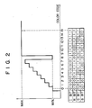
- Fig. 2 is a diagrammatic representation showing the relationship between the color codes, the tone levels and the I, R, G and B bits in a 9-tone system.
- an intensity (I) bit is set at logic "0”
- eight color codes represented by the 3-bit data of R-G-B are assigned to eight tone levels, respectively.
- the I bit is set at logic "1”
- the maximum level is assigned to the color code irrespective of the 3-bit data of R•G•B.
- the color codes are assigned with a total of 9 tone levels.
- Fig. 3 is a block diagram of a monochromatic tone display apparatus according to an embodiment of the present invention.
- a horizontal synchronizing signal (HSYNC) and a vertical synchronizing signal (VSYNC) generated from a display controller (not shown) are supplied to a non-exclusive OR gate 11.
- the I bit (the intensity signal) is supplied to one input terminal of an AND gate 17.
- the R, G and B signals are supplied to an OR gate 18 and one input terminal of each of the OR gates 13, 14 and 15.
- An output signal from the OR gate 18 is supplied to the other input terminal of the AND gate 17 and a buffer 16.
- An output signal from the AND gate 17 is supplied to a buffer 12 and the other input terminal of each of the OR gates 13, 14 and 15.
- the buffer 12, the OR gates 13, 14 and 15, and the buffer 1 6 are commonly connected to an amplifier 19 through corresponding resistors R12, R13, R14, R15 and R16.
- An output terminal of the non-exclusive OR gate 11 is connected to output terminals of the gates 13 through 1 5 and the buffers 12 and 16.
- the non-exclusive OR gate 11 is also connected to a power source voltage VCC through the resistor Rll, and grounded through resistor R17.
- the buffers 12 and 16 are arranged to synchronize with propagation delay times of the gates 13 through 15.
- the OR gate 11 When one of the HSYNC and VSYNC signals is set at logic "1", the OR gate 11 generates a logic "0" signal.
- the OR gate 18 When one of the R, G or B signals is set at logic "1”, the OR gate 18 generates an output signal of logic "1". This output signal is supplied to the other input terminal of the AND gate 17.
- the AND gate 17 When the I signal is set at logic "1", the AND gate 17 generates, through the buffer 12, a signal indicating that the tone is of the maximum level.
- the OR gate 13 generates a signal indicating, similarly, that the R signal is of the maximum level
- the OR gate 14 generates a signal indicating that the G signal is of the maximum level
- the OR gate 15 generates a signal indicating that the B signal is of the maximum level
- the buffer 16 generates a signal indicating that one of the R, G and B signals is present.
- the resistor Rll constitutes a pull-up resistor; R12 through R16, open collector resistors for the buffer 12, the OR gates 13 through 15, and the buffer 16; and R17, a pull-down resistor. These resistors constitute an adder from which the total voltage from the active resistors is applied to the amplifier 19.
- the resistors R15 and R16 are active. A total voltage from the resistors R15 and R16 is applied to the amplifier 19. Furthermore, when only the G signal is set at logic "1", the resistors R14 and R16 are active. The total resistance of the resistors R14 and R16 is smaller than that of the resistors R15 and R16, so that the total voltage from the resistors R14 and R16 is higher than that of the resistors R15 and R16. Similarly, when the R, G and B signals are set at logic "1", the resistors R13, R14 and R15 are active. The total voltage from the resistors R13 through R16 is applied to the amplifier 19. As shown in Fig. 2, the tone level is increased in a stepwise manner.
Landscapes
- Engineering & Computer Science (AREA)
- Physics & Mathematics (AREA)
- Computer Hardware Design (AREA)
- General Physics & Mathematics (AREA)
- Theoretical Computer Science (AREA)
- Remote Sensing (AREA)
- Radar, Positioning & Navigation (AREA)
- Controls And Circuits For Display Device (AREA)
- Processing Of Color Television Signals (AREA)
- Control Of Indicators Other Than Cathode Ray Tubes (AREA)
- Liquid Crystal Display Device Control (AREA)
- Television Receiver Circuits (AREA)
- Digital Computer Display Output (AREA)
- Studio Circuits (AREA)
Applications Claiming Priority (2)
| Application Number | Priority Date | Filing Date | Title |
|---|---|---|---|
| JP39256/85 | 1985-02-28 | ||
| JP60039256A JPS61198275A (ja) | 1985-02-28 | 1985-02-28 | モノクロ階調表示装置 |
Publications (3)
| Publication Number | Publication Date |
|---|---|
| EP0192815A2 true EP0192815A2 (de) | 1986-09-03 |
| EP0192815A3 EP0192815A3 (en) | 1989-09-13 |
| EP0192815B1 EP0192815B1 (de) | 1992-11-19 |
Family
ID=12548055
Family Applications (1)
| Application Number | Title | Priority Date | Filing Date |
|---|---|---|---|
| EP85111449A Expired - Lifetime EP0192815B1 (de) | 1985-02-28 | 1985-09-10 | Tonsteuergerät in einer monochromen Tonanzeigeeinrichtung |
Country Status (6)
| Country | Link |
|---|---|
| US (1) | US4725833A (de) |
| EP (1) | EP0192815B1 (de) |
| JP (1) | JPS61198275A (de) |
| KR (1) | KR890005188B1 (de) |
| CN (1) | CN85107364A (de) |
| DE (1) | DE3586846T2 (de) |
Cited By (4)
| Publication number | Priority date | Publication date | Assignee | Title |
|---|---|---|---|---|
| EP0285250A3 (de) * | 1987-03-31 | 1990-05-23 | Ing. C. Olivetti & C., S.p.A. | Gerät zur Anzeige von Verarbeitungsdaten mittels Bildelementen auf einer Kathodenstrahlröhre |
| EP0347720A3 (en) * | 1988-06-18 | 1990-06-13 | Hitachi, Ltd. | Apparatus and method for gray scale display |
| EP0395735A4 (en) * | 1988-01-15 | 1991-12-11 | Chips And Technologies, Inc. | Color to monochrome conversion |
| US5245327A (en) * | 1988-01-15 | 1993-09-14 | Chips And Technologies, Incorporated | Color to monochrome conversion |
Families Citing this family (11)
| Publication number | Priority date | Publication date | Assignee | Title |
|---|---|---|---|---|
| JPS62244090A (ja) * | 1986-04-16 | 1987-10-24 | アンリツ株式会社 | 表示装置 |
| US5153577A (en) * | 1986-04-28 | 1992-10-06 | Xerox Corporation | Mapping character color attributes into grey pixel patterns |
| JPH0774944B2 (ja) * | 1986-10-30 | 1995-08-09 | パイオニア株式会社 | 車載ナビゲ−シヨン装置における表示装置 |
| US4818982A (en) * | 1987-08-12 | 1989-04-04 | Systems Management American Corporation | Brightness control for an electro-luminescent display |
| JPS6491175A (en) * | 1987-10-02 | 1989-04-10 | Fanuc Ltd | Display device |
| US5148518A (en) * | 1987-10-31 | 1992-09-15 | Kabushiki Kaisha Toshiba | Computer system with monochrome display unit capable of converting color code to gradation code |
| US4977398A (en) * | 1988-01-15 | 1990-12-11 | Chips And Technologies, Incorporated | Color to monochrome conversion |
| JP2769345B2 (ja) * | 1989-02-21 | 1998-06-25 | 三菱電機株式会社 | 表示制御装置 |
| DE4031905C2 (de) * | 1989-10-09 | 1993-12-09 | Hitachi Ltd | Mehrpegel-Anzeigesystem und Verfahren zur Darstellung von Grautönen mit einem solchen System |
| US5712657A (en) * | 1995-03-28 | 1998-01-27 | Cirrus Logic, Inc. | Method and apparatus for adaptive dithering |
| TWI267049B (en) * | 2000-05-09 | 2006-11-21 | Sharp Kk | Image display device, and electronic apparatus using the same |
Family Cites Families (4)
| Publication number | Priority date | Publication date | Assignee | Title |
|---|---|---|---|---|
| US4158200A (en) * | 1977-09-26 | 1979-06-12 | Burroughs Corporation | Digital video display system with a plurality of gray-scale levels |
| NL7801690A (nl) * | 1978-02-15 | 1979-08-17 | Philips Nv | Monochrome beeldweergeefinrichting. |
| US4251755A (en) * | 1979-07-12 | 1981-02-17 | Raytheon Company | CRT Digital brightness control |
| FR2506623A1 (fr) * | 1981-06-01 | 1982-12-03 | Radiotechnique | Generateur de signaux video trichromes, tel qu'un jeu video, utilisable avec un reproducteur d'images monochrome |
-
1985
- 1985-02-28 JP JP60039256A patent/JPS61198275A/ja active Pending
- 1985-06-28 KR KR1019850004636A patent/KR890005188B1/ko not_active Expired
- 1985-09-10 DE DE8585111449T patent/DE3586846T2/de not_active Expired - Fee Related
- 1985-09-10 EP EP85111449A patent/EP0192815B1/de not_active Expired - Lifetime
- 1985-09-29 CN CN198585107364A patent/CN85107364A/zh active Pending
- 1985-10-01 US US06/782,398 patent/US4725833A/en not_active Expired - Fee Related
Cited By (5)
| Publication number | Priority date | Publication date | Assignee | Title |
|---|---|---|---|---|
| EP0285250A3 (de) * | 1987-03-31 | 1990-05-23 | Ing. C. Olivetti & C., S.p.A. | Gerät zur Anzeige von Verarbeitungsdaten mittels Bildelementen auf einer Kathodenstrahlröhre |
| EP0395735A4 (en) * | 1988-01-15 | 1991-12-11 | Chips And Technologies, Inc. | Color to monochrome conversion |
| US5245327A (en) * | 1988-01-15 | 1993-09-14 | Chips And Technologies, Incorporated | Color to monochrome conversion |
| EP0347720A3 (en) * | 1988-06-18 | 1990-06-13 | Hitachi, Ltd. | Apparatus and method for gray scale display |
| US5119086A (en) * | 1988-06-18 | 1992-06-02 | Hitachi Ltd. | Apparatus and method for gray scale display |
Also Published As
| Publication number | Publication date |
|---|---|
| DE3586846D1 (de) | 1992-12-24 |
| JPS61198275A (ja) | 1986-09-02 |
| CN85107364A (zh) | 1986-08-27 |
| US4725833A (en) | 1988-02-16 |
| KR860006689A (ko) | 1986-09-13 |
| DE3586846T2 (de) | 1993-04-01 |
| EP0192815A3 (en) | 1989-09-13 |
| KR890005188B1 (ko) | 1989-12-16 |
| EP0192815B1 (de) | 1992-11-19 |
Similar Documents
| Publication | Publication Date | Title |
|---|---|---|
| EP0192815A2 (de) | Tonsteuergerät in einer monochromen Tonanzeigeeinrichtung | |
| EP0170816B1 (de) | Digitales Anzeigesystem mit einer nach dem Rasterverfahren arbeitenden Anzeigeröhre | |
| GB1599734A (en) | Microcomputer for use with a video display | |
| US4727414A (en) | Circuit for converting digital signals representing color information into analog voltage level signals with enhanced contrast between foreground and background | |
| US4527154A (en) | Display system | |
| US5225819A (en) | Screen display device | |
| US4922237A (en) | Flat panel display control apparatus | |
| US4583119A (en) | Signal interface circuit | |
| JPH0879312A (ja) | データ伝送システム及び方法 | |
| US5257015A (en) | Flat panel display control apparatus | |
| EP0273749B1 (de) | Anzeigesystem mit weniger Anzeigespeicherchips | |
| US4857909A (en) | Image display apparatus | |
| JPH01174077A (ja) | 映像信号処理装置 | |
| EP0177889B1 (de) | Einrichtung zum Steuern eines Kathodenstrahlanzeigegerätes | |
| JPH0456318B2 (de) | ||
| JPS58198086A (ja) | 文字表示装置 | |
| JPH03139696A (ja) | モノクロcrtの階調制御装置 | |
| KR0185588B1 (ko) | 그래픽처리회로 및 방법 | |
| JPS6234195A (ja) | 自動位相検出回路 | |
| JP2700650B2 (ja) | ビデオ信号生成回路 | |
| JPS5977487A (ja) | パタ−ン表示駆動装置 | |
| KR890001794B1 (ko) | 코드 중복 사용 디스플레이 회로 | |
| KR950005823Y1 (ko) | Ibm 퍼스널 컴퓨터에서의 다개국어 제어장치 | |
| KR920001160B1 (ko) | 비데오 테이프 레코오더 녹화시 온스크린문자 녹화회로 | |
| JPH0637854A (ja) | データ伝送装置 |
Legal Events
| Date | Code | Title | Description |
|---|---|---|---|
| PUAI | Public reference made under article 153(3) epc to a published international application that has entered the european phase |
Free format text: ORIGINAL CODE: 0009012 |
|
| 17P | Request for examination filed |
Effective date: 19851007 |
|
| AK | Designated contracting states |
Kind code of ref document: A2 Designated state(s): DE FR GB |
|
| PUAL | Search report despatched |
Free format text: ORIGINAL CODE: 0009013 |
|
| AK | Designated contracting states |
Kind code of ref document: A3 Designated state(s): DE FR GB |
|
| 17Q | First examination report despatched |
Effective date: 19910116 |
|
| GRAA | (expected) grant |
Free format text: ORIGINAL CODE: 0009210 |
|
| AK | Designated contracting states |
Kind code of ref document: B1 Designated state(s): DE FR GB |
|
| REF | Corresponds to: |
Ref document number: 3586846 Country of ref document: DE Date of ref document: 19921224 |
|
| ET | Fr: translation filed | ||
| PLBE | No opposition filed within time limit |
Free format text: ORIGINAL CODE: 0009261 |
|
| STAA | Information on the status of an ep patent application or granted ep patent |
Free format text: STATUS: NO OPPOSITION FILED WITHIN TIME LIMIT |
|
| 26N | No opposition filed | ||
| PGFP | Annual fee paid to national office [announced via postgrant information from national office to epo] |
Ref country code: GB Payment date: 19940831 Year of fee payment: 10 |
|
| PGFP | Annual fee paid to national office [announced via postgrant information from national office to epo] |
Ref country code: DE Payment date: 19940908 Year of fee payment: 10 |
|
| PGFP | Annual fee paid to national office [announced via postgrant information from national office to epo] |
Ref country code: FR Payment date: 19940909 Year of fee payment: 10 |
|
| PG25 | Lapsed in a contracting state [announced via postgrant information from national office to epo] |
Ref country code: GB Effective date: 19950910 |
|
| GBPC | Gb: european patent ceased through non-payment of renewal fee |
Effective date: 19950910 |
|
| PG25 | Lapsed in a contracting state [announced via postgrant information from national office to epo] |
Ref country code: FR Effective date: 19960531 |
|
| PG25 | Lapsed in a contracting state [announced via postgrant information from national office to epo] |
Ref country code: DE Effective date: 19960601 |
|
| REG | Reference to a national code |
Ref country code: FR Ref legal event code: ST |