EP0192825A2 - Récipient distributeur à piston - Google Patents
Récipient distributeur à piston Download PDFInfo
- Publication number
- EP0192825A2 EP0192825A2 EP85114839A EP85114839A EP0192825A2 EP 0192825 A2 EP0192825 A2 EP 0192825A2 EP 85114839 A EP85114839 A EP 85114839A EP 85114839 A EP85114839 A EP 85114839A EP 0192825 A2 EP0192825 A2 EP 0192825A2
- Authority
- EP
- European Patent Office
- Prior art keywords
- container
- piston
- piston plate
- plate
- open
- Prior art date
- Legal status (The legal status is an assumption and is not a legal conclusion. Google has not performed a legal analysis and makes no representation as to the accuracy of the status listed.)
- Withdrawn
Links
- 238000004873 anchoring Methods 0.000 claims description 2
- 238000007789 sealing Methods 0.000 description 5
- 239000000463 material Substances 0.000 description 3
- 239000002781 deodorant agent Substances 0.000 description 2
- 238000011161 development Methods 0.000 description 2
- 230000018109 developmental process Effects 0.000 description 2
- 238000001125 extrusion Methods 0.000 description 2
- 239000007788 liquid Substances 0.000 description 2
- 238000007788 roughening Methods 0.000 description 2
- 238000013459 approach Methods 0.000 description 1
- 239000011324 bead Substances 0.000 description 1
- 230000015572 biosynthetic process Effects 0.000 description 1
- 230000002349 favourable effect Effects 0.000 description 1
- 238000003780 insertion Methods 0.000 description 1
- 230000037431 insertion Effects 0.000 description 1
- 238000009434 installation Methods 0.000 description 1
- 239000000126 substance Substances 0.000 description 1
- 230000008719 thickening Effects 0.000 description 1
- 229940034610 toothpaste Drugs 0.000 description 1
- 239000000606 toothpaste Substances 0.000 description 1
- 239000011800 void material Substances 0.000 description 1
Images


Classifications
-
- B—PERFORMING OPERATIONS; TRANSPORTING
- B65—CONVEYING; PACKING; STORING; HANDLING THIN OR FILAMENTARY MATERIAL
- B65D—CONTAINERS FOR STORAGE OR TRANSPORT OF ARTICLES OR MATERIALS, e.g. BAGS, BARRELS, BOTTLES, BOXES, CANS, CARTONS, CRATES, DRUMS, JARS, TANKS, HOPPERS, FORWARDING CONTAINERS; ACCESSORIES, CLOSURES, OR FITTINGS THEREFOR; PACKAGING ELEMENTS; PACKAGES
- B65D83/00—Containers or packages with special means for dispensing contents
- B65D83/76—Containers or packages with special means for dispensing contents for dispensing fluent contents by means of a piston
- B65D83/767—Containers or packages with special means for dispensing contents for dispensing fluent contents by means of a piston the piston having an integrated dispensing opening
Definitions
- the invention relates to a container designed in the manner of a cover-lockable tube with an extrusion piston and an air passage zone in the region of the piston to be inserted from the open end after the container has been filled.
- Toothpaste dispensers are filled with the head piece pointing downwards from the open bottom end.
- the piston is then inserted from there.
- the air trapped between the filled mass and the free end can escape through roughened wall sections in the end region of the container. This avoids deceptive fillings and favors the desired safe functioning of the dispensing mechanism of such dispensing containers.
- Complex filling systems are necessary. In the case of so-called deodorant sticks, such roughening of the cylinder inner wall of the housing cannot be used satisfactorily for reasons of the hard-pasty substance.
- the object of the invention is to provide a generic container with an ejection piston, in which the air cushion building up in the manner mentioned is compensated for or evacuated with the simplest means even without such roughening.
- a generic container of increased utility value is achieved: between the leading, ie. H. Piston plate facing the container contents and air enclosed in this content escapes via the central sleeve into the annular space surrounding the sleeve.
- This annular space initially still has a connection to the outside air, since the second piston plate only enters the container at the last moment.
- the bush can even take up part of the mass, which results in an advantageous anchoring. In order to avoid clogging of the transverse opening, it extends as far as possible from the piston plate on the container side.
- Piston plate has a cuff-like piston lip which lifts off the inner wall of the container if there is overpressure in the annular space.
- the limit value of the internal pressure in the annular space resulting from the contact pressure of this piston plate also favors the fact that void spaces are avoided when the mass solidifies.
- the piston plate which is further away from the container contents, has the air passage zone in the form of an opening on its wide surface.
- the piston plate facing the container contents has a piston lip pointing in the direction of the container contents. This wipes the leading inside wall of the container clean. The corresponding alignment of the lip even favors the sealing system due to a correspondingly directed pressure component of the mass.
- the piston plate facing the container contents has a collar anchored in the container contents with longitudinal slots which extend as far as the top side of the piston plate, there is an intimate bond with the hardening, pin-forming material.
- the container 1 designed in the manner of a tube for deodorant pens, ski wax or the like has an elliptical cross section and contains a cross section corresponding to the piston 2 which can be axially displaced in the container.
- One open end of the container 2 forms a flat edge 3 as a standing edge.
- the edge 3 appears in FIG. 1 above, since this illustration contributes to a better understanding with regard to the filling of the container.
- the other open end of the container 1 forms an outlet opening 4.
- the latter is covered by a cap-like cover 5. This holds frictionally in plug-in assignment.
- the end region of the container 1 there has a stepped plug-in projection 1 '.
- the cover 5 On the inside, the cover 5 has a sealing cone 6. The latter strikes the correspondingly offset front edge 1 "of the plug-in projection 1 '.
- the inclined surfaces are at 45 °. As can be seen in FIG. 1, the remaining section of the sealing cone, which is not included in the seal, settles '6 continues, resulting in a protrusion of the pin formed by the container content M, which facilitates the application of the stiffened mass.
- the length section of the container 1 which is inserted into the inserted piston 2 is approximately twice as large as the container section receiving the stock of pin-forming mass. With regard to these aspect ratios, it is ensured that the squeezing piston 2 can still be comfortably brought into its feed position allowing the remaining output with the finger of the operating hand.
- the relevant air passage zone is at the bottom, i.e. H. stand-forming end of the container.
- the relevant structure is such that the squeeze-out piston 2 forms two piston plates a and b which are connected to one another by a bushing 7. Their clear distance from each other is about three quarters of the larger ellipse diameter.
- the annular space formed in the axial direction by the piston plate bottoms directed against one another and in the radial direction by the jacket wall of the bushing 7 and the inner wall 8 of the container has the reference symbol R.
- the sleeve 7 is circular in cross section and closed at the outer end. This closed end of the sleeve 7 forms a tactile surface 9 on the outside, the latter being dented, as can be seen in FIG. 1.
- the tactile surface 9 is seated on a pot 10 protruding outward from the piston plate and slightly offset from the bushing 7.
- the tactile surface occupies a central position, so that the actuating forces to be introduced via it act centrally on the squeezing piston 2, that is to say the flow of force in the direction of Longitudinal central axis xx of the container lies.
- Both piston plates each have a cuff-like piston lip.
- the piston lip of the piston plate a facing the container content M faces the end of the container 1 which has the outlet opening 4 and bears the reference number 11. It bears tightly against the inner wall 8 of the said container 1 with slight pretension, namely only its free end section. Otherwise, the lip stands out from the inner wall for the entire remaining length.
- the piston lip of the piston plate b facing away from the container content M is directed towards the open end of the container 1 and carries this Reference numeral 12.
- the statements made with regard to the piston lip 11 apply.
- the edge 3 of the open container end is chamfered on the inner flank in a roof shape.
- the helix angle is approx. 45 ° and leads to a funnel that tapers towards the inside of the container.
- the slanted inner flank is designated 13.
- the piston lip 12 of the piston plate b is flush with the pot 10 of the plunger forming the tactile surface 9.
- the height of the pot corresponds to about a third of the bush diameter.
- the piston lip 11 of the piston plate a facing the container contents is level with a collar 14 molded onto this plate in the direction mentioned.
- the latter practically continues axially in the plane of the sleeve wall and ends at the free end in a radially protruding bead 15.
- the material thickening in this regard leads to an intimate bond with the solidifying, pin-forming container contents.
- the collar 14 has longitudinal slots 16 on diametrically opposite sides, preferably lying in the direction of the longer ellipse axis y-y. The latter extend over the entire length, i. H. axial height of the collar 14, so end at the level of the piston plate top level with this.
- the sleeve 7, which is open towards the container contents, has at least one transverse opening 17 near the piston plate b which is more distant from the container contents. This gives way to the air enclosed between the mirror Sp of the container contents and the piston plate a, which air enters the cavity the sleeve 7 is urged into the annular space R surrounding the sleeve 7. Before the piston plate b facing away from the container contents. Press plunger assignment in leading system to the inner wall 8 of the container 1, the air displaced therefrom can still escape in this air passage zone.
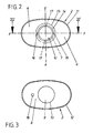
- the piston plate b facing away from the container contents has an air passage zone in the form of an opening 18 on its broad surface (see FIGS. 1 and 3).
- the opening 18 lies in the longer ellipse axis yy, while the (17) of the sleeve 7 are arranged transversely thereto, ie in the shorter ellipse axis zz.
Landscapes
- Engineering & Computer Science (AREA)
- Mechanical Engineering (AREA)
- Closures For Containers (AREA)
- Containers And Packaging Bodies Having A Special Means To Remove Contents (AREA)
Applications Claiming Priority (2)
| Application Number | Priority Date | Filing Date | Title |
|---|---|---|---|
| DE3506003 | 1985-02-21 | ||
| DE19853506003 DE3506003A1 (de) | 1985-02-21 | 1985-02-21 | Behaelter mit auspresskolben |
Publications (2)
| Publication Number | Publication Date |
|---|---|
| EP0192825A2 true EP0192825A2 (fr) | 1986-09-03 |
| EP0192825A3 EP0192825A3 (fr) | 1987-10-07 |
Family
ID=6263139
Family Applications (1)
| Application Number | Title | Priority Date | Filing Date |
|---|---|---|---|
| EP85114839A Withdrawn EP0192825A3 (fr) | 1985-02-21 | 1985-11-22 | Récipient distributeur à piston |
Country Status (2)
| Country | Link |
|---|---|
| EP (1) | EP0192825A3 (fr) |
| DE (1) | DE3506003A1 (fr) |
Cited By (1)
| Publication number | Priority date | Publication date | Assignee | Title |
|---|---|---|---|---|
| EP1897463A3 (fr) * | 2006-09-07 | 2009-07-22 | L'oreal | Système d'aération pour dispositif de distribution de produit |
Family Cites Families (3)
| Publication number | Priority date | Publication date | Assignee | Title |
|---|---|---|---|---|
| FR1458448A (fr) * | 1965-09-13 | 1966-03-04 | Oreal | Nouveau procédé pour effectuer le remplissage d'étuis ou de récipients contenantdes bâtons de substance solidifiée, et nouveaux produits pour mettre en oeuvre ce procédé |
| DE2132249A1 (de) * | 1971-06-29 | 1973-01-11 | Victor Fritz | Kolbendose mit auftraeger |
| DE3038917A1 (de) * | 1980-10-15 | 1982-05-27 | Roder, Gottfried, 2400 Lübeck | Verschluss fuer pasten oder fluessigkeit aufnehmende behaelter |
-
1985
- 1985-02-21 DE DE19853506003 patent/DE3506003A1/de not_active Withdrawn
- 1985-11-22 EP EP85114839A patent/EP0192825A3/fr not_active Withdrawn
Cited By (2)
| Publication number | Priority date | Publication date | Assignee | Title |
|---|---|---|---|---|
| EP1897463A3 (fr) * | 2006-09-07 | 2009-07-22 | L'oreal | Système d'aération pour dispositif de distribution de produit |
| US7874464B2 (en) * | 2006-09-07 | 2011-01-25 | L'oreal | Venting system for a product dispensing device |
Also Published As
| Publication number | Publication date |
|---|---|
| EP0192825A3 (fr) | 1987-10-07 |
| DE3506003A1 (de) | 1986-08-21 |
Similar Documents
| Publication | Publication Date | Title |
|---|---|---|
| EP0144879B1 (fr) | Distributeur pour matériaux pâteux, notamment distributeur de pâtes dentifrices | |
| EP0036491B1 (fr) | Distributeur pour produits pâteux | |
| EP0254969B1 (fr) | Dispositif pour l'extrusion de matières pâteuses | |
| DE69518222T2 (de) | An verschiedene Behälter anpassbare Dosiervorrichtung | |
| DE9217916U1 (de) | Adapter für Spritzvorrichtungen zum Ausbringen von extrudierbaren Materialien aus wurstförmigen Packungen mit flexiblen Hüllen | |
| EP0152373A2 (fr) | Piston de pression pour récipients | |
| EP0363967A2 (fr) | Pistolet d'extrusion pour cartouches à double paroi | |
| EP0160785A2 (fr) | Distributeur de produits pâteux | |
| DE68904004T2 (de) | Spender fuer pastoese produkte, insbesondere fuer zahnpasta. | |
| DE2536858A1 (de) | Kolben-dosierpumpe | |
| EP3405293B1 (fr) | Emballage de feuilles et bloc comprenant un dispositif de compression et un emballage de feuilles | |
| DE3202275A1 (de) | Einhandbetaetigter behaelter zur abgabe gleicher oder verschiedener volumenmengen viskoser fuellgueter sowie seine befuellung | |
| EP0315077B1 (fr) | Distributeur pour produits pâteux | |
| DE69120429T2 (de) | Dosier- und ausgiessvorrichtung | |
| DE10207763A1 (de) | Mehrkomponenten-Kartusche | |
| DE3635849C2 (de) | Spender | |
| EP1344570B1 (fr) | Distributeur des produits fluides | |
| DE3143319A1 (de) | Flaschen-ausgiesser | |
| EP0282791A2 (fr) | Distributeur pour produits pâteux | |
| DE3343680A1 (de) | Spender fuer pastoese massen, insbesondere zahncremespender | |
| EP0184742A2 (fr) | Distributeur pour la décharge en portion unique de pastilles, pâtes ou similaires | |
| DE3506003A1 (de) | Behaelter mit auspresskolben | |
| DE3618399A1 (de) | Spender | |
| EP0481250A1 (fr) | Cartouche destinée à être introduite dans un distributeur | |
| DE4418394C2 (de) | Kartusche |
Legal Events
| Date | Code | Title | Description |
|---|---|---|---|
| PUAI | Public reference made under article 153(3) epc to a published international application that has entered the european phase |
Free format text: ORIGINAL CODE: 0009012 |
|
| AK | Designated contracting states |
Kind code of ref document: A2 Designated state(s): AT BE CH DE FR GB IT LI LU NL SE |
|
| PUAL | Search report despatched |
Free format text: ORIGINAL CODE: 0009013 |
|
| AK | Designated contracting states |
Kind code of ref document: A3 Designated state(s): AT BE CH DE FR GB IT LI LU NL SE |
|
| 17P | Request for examination filed |
Effective date: 19871016 |
|
| 17Q | First examination report despatched |
Effective date: 19880909 |
|
| STAA | Information on the status of an ep patent application or granted ep patent |
Free format text: STATUS: THE APPLICATION IS DEEMED TO BE WITHDRAWN |
|
| 18D | Application deemed to be withdrawn |
Effective date: 19890103 |
|
| RIN1 | Information on inventor provided before grant (corrected) |
Inventor name: BAHLMANN, FRANZ-JOSEF Inventor name: HACKMANN, LUDGER |