EP0193100A2 - Sous-système de communication - Google Patents
Sous-système de communication Download PDFInfo
- Publication number
- EP0193100A2 EP0193100A2 EP86102159A EP86102159A EP0193100A2 EP 0193100 A2 EP0193100 A2 EP 0193100A2 EP 86102159 A EP86102159 A EP 86102159A EP 86102159 A EP86102159 A EP 86102159A EP 0193100 A2 EP0193100 A2 EP 0193100A2
- Authority
- EP
- European Patent Office
- Prior art keywords
- bus
- interface
- controller
- communication subsystem
- data
- Prior art date
- Legal status (The legal status is an assumption and is not a legal conclusion. Google has not performed a legal analysis and makes no representation as to the accuracy of the status listed.)
- Withdrawn
Links
Images

Classifications
-
- H—ELECTRICITY
- H04—ELECTRIC COMMUNICATION TECHNIQUE
- H04Q—SELECTING
- H04Q11/00—Selecting arrangements for multiplex systems
- H04Q11/04—Selecting arrangements for multiplex systems for time-division multiplexing
- H04Q11/0407—Selecting arrangements for multiplex systems for time-division multiplexing using a stored program control
-
- H—ELECTRICITY
- H04—ELECTRIC COMMUNICATION TECHNIQUE
- H04L—TRANSMISSION OF DIGITAL INFORMATION, e.g. TELEGRAPHIC COMMUNICATION
- H04L12/00—Data switching networks
- H04L12/54—Store-and-forward switching systems
- H04L12/56—Packet switching systems
Definitions
- the present invention relates to a communication subsystem and, in particular, relates to such a subsystem having a distributed masterless multi-microcomputer architecture.
- the architecture essentially includes a digital switching network DSN having a plurality of terminal control elements (TCE) interconnected thereto and thereby.
- TCE terminal control elements
- Each TCE includes the necessary means for path control between subscribers to different TCE's. Consequently, in the event of a failure in the DSN each TCE nevertheless provides full services to the subscribers thereto, and in the event of a failure in any TCE, the remaining TCEs and DSN provide full service to the subscriber thereto.
- the provision of alternate, or redundant paths and services can readily be provided and this further reduces any impact of any failure on the subscribers to a particular TCE.
- each TCE can be expanded in a modular fashion.
- the number of TCE's interconnected to a DSN can be modularly increased.
- LAN local area network
- PABX's circuit switched exchanges
- the object of the present invention is to provide a communication subsystem that overcomes the above recited difficulties.
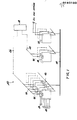
- a communication subsystem generally indicated at 10 in Figure 1 and embodying the principles of the present invention, includes means 12 for interfacing with a plurality of peripherals 14, means 16 for interfacing with a networking medium 18 and means 20 for establishing data communication between and among the peripheral interface means 12 and the networking medium interfacing means 16.
- the subsystem 10 preferably includes means 22 for providing access to auxiliary services, the means 22 being interconnected with the data communication establishing means 20.
- means 22 is adapted to communicate data with the peripheral interface means 12 and/or the networking medium interfacing means 16.
- the communication subsystem 10 includes a data PCM bus 24 interconnecting the networking medium interface means 16 and the networking medium 18.
- the subsystem 10 includes a voice PCM bus 26 interconnecting the peripheral
- peripheral interfacing means 12 and the networking medium interfacing means 16 are substantially identical in the hardware implementation thereof.
- auxiliary services providing means 22 is, essentially, identical to the means 12 and 16.
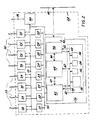
- the means 12 for interfacing with a plurality of peripherals 14 includes a plurality of substantially identical peripheral interface devices, one being generally indicated at 28 in Figure 2, each of which is adapted to interface with voice and/or data peripherals via, for example, a plurality of twisted pairs of wires 30.
- peripheral interface devices may be interconnected via coaxial cables, fiber optic links or the like with the associated peripheral interface device 28 adapted therefor.
- each peripheral interface device 28 includes a data transport controller 32 effectively interconnected between a plurality of universal synchronous/asynchronous receive/transmit (USART) devices 34 and the means 20, hereinafter referred to as the intrasubsystem bus.
- USB universal synchronous/asynchronous receive/transmit
- each peripheral interface device 28 includes a subscriber loop interface 36 associated with each pair of twisted wires 30.
- Each subscriber loop interface 36 exchanges data information with one of the USARTs 34 and exchanges voice information with a local voice bus 38 which voice bus 38 is interconnected with a pulse-coded-modulation (PCM) .bus interface device 40.
- PCM pulse-coded-modulation
- the data transport controller 32 includes a device interface controller 42, a storage medium 44, a bus interface controller 46, with an associated bus interface 47, and a microcomputer 48.
- the microcomputer 48 preferably includes a microprocessor portion 50, a random-access-memory (RAM) 52, a read-only-memory (ROM) 54 and a miscellaneous program storage means 56.
- the microprocessor portion 50, the RAM 52, the ROM S4 and the means 56 are interconnected via a local microcomputer bus S8.
- the device interface controller 42 and the bus interface controller 46 each have direct communication with the microcomputer 48 only via a set of interrupt/channel attention lines, 60 and 62, respectively.
- the device interface controller 42 and the bus interface controller 46 effectively, independently interconnect with the storage medium 44 via separate address/data buses, 64 and 66, respectively.
- the microcomputer 48 interconnects with the storage medium via bus 68 which supports control, address and data exchanges therebetween.
- the intrasubsystem bus 20 is, preferably, a masterless multiple-access bus with collision detection.
- the intrasubsystem bus 20 includes a data transport medium, a collision detection medium and a clock signal maximra; the data transport Medium being separate and distinct from the collision detection medium.
- the device interface controller 42 is adapted to support a high speed bus 70 that interfaces with a plurality of data peripherals via the USART 34.
- each of the USARTs 34 would effectively, be directly interconnected to a respective one of the plurality of sets of twisted pairs of wires 30.
- each USART 34 is implemented via one-half of a 8274 HDLC controller manufactured and marked by Intel Copr. of Stana Clara, California.
- the peripheral interface device 28 is adapted for both voice and data communication.
- the subscriber loop interface 36 inter alia, multiplex/demultiplex the voice and data information establishing a voice path with local voice bus 38 via the PCM bus interface device 40.
- a block diagram of a preferred subscriber loop interface 36 is shown in Figure 3 and includes a short digital loop 72, an encoder/decoder 74, a mode controller 76, a line adaptation circuit 78 and a line synchronization device 80 for synchronizing the line adaptation procedure.
- the PCM bus interface device 40 is adapted to receive voice information and establish paths for the voice information to the local voice bus 38 which bus 38, for example, can provide up to 30 full duplex.
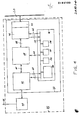
- the means 16 for interfacing with a networking medium 18 includes at least one network interface device 82.
- a typical network interface device 82 is shown in the block diagram of Figure 4 wherein previously assigned identification numerals are used to identify previously discussed elements.
- the network interface device 82 includes a data transport controller 32 interconnected between the intrasubsystem bus 20 and a PCM bus interface device 40.
- the PCM bus interface device 40 interfacing with the data PCM bus 24 that interconnects with the network medium 18.
- the data transport controller 32 is, in the hardware implementation thereof, substantially completely identical to the data transport controller 32 employed on each peripheral interface device 28. That is, the same data transport controller 32, as a module, is universally used in every peripheral interface device 28 and every network interface device 82 in the subsystem 10. As more fully discussed below the only difference between the data transport controllers 32 used on the peripheral interface devices 28 and the network interface devices 82 is the tasks assigned thereto by software programs downloaded thereinto.
- the means 22 for providing auxiliary services includes gateway interface device having a substantially identical data transport controller 32.
- the specific design of such gateway interface devices essentially, depends upon the auxiliary services or other networking to be provided and are programmed to execute the necessary communication protocol conversion between the protocol of the bus 20 and that of the service provider.
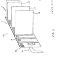
- the communication subsystem 10 includes a master printed circuit board assembly 86 having the intrasubsystem bus 20 formed thereon and having a plurality of printed circuit board connectors 88 affixed thereto.
- a first trunkline 90 is provided to interconnect with the peripherals 14 and a second trunkline, not shown, is provided to interconnect with the networking medium 18.
- each peripheral interface device 28 is implemented on a dedicated printed circuit board assembly 92
- each network interface device 82 is implemented on a dedicated printed circuit board assembly 94
- each gateway interface device is implemented on a single printed circuit board assembly 96.
- the subsystem 10 is modularly expandable with a minimal initial investment.
- each peripheral interface device 28 interconnects with a plurality of peripherals 14 all of which peripherals 14 operate acccording to the same communication protocol. Further, due, in part, to the universal inclusion of a common data transport controller 32 or each device,22, 2B and 82, the subsystem 10, and, preferably any network incorporating such subsystems 10 includes a uniform protocol. Hence, by assigning each peripheral interface cevice 28 to peripherals 14 of a common communication protocol tie number of communication protocol conversions, and the r-sultant traffic loading is reduced.
- each data transport controller 32 is, inter alia, a microcomputer and, preferably, adapted to autonomously control all traffic thereacross.
- the subsystem 10 has the paramount advantage of avoiding catastrophic failure due to any one element failure and, in fact, is capable of providing continuous, albeit reduced, services in the event of multiple element failures.
- the subsystem 10 primarily because of the use of a common data transport controller 32 in addition to the modular multi-microcomputer distributed control architecture, is thus extremely versatile.
- the subsystem 10 can be used as a common, or universal, data subsystem in a data communication network.
- the ITT SYSTEM 12 digital exchange can be used as the networking medium 18 hereof and the data PCM bus 24 of each subsysetm 10 is directly interconnected thereto.
- the versatility and growth aspects of the communication subsystem 10 are such that the subsystem 10, with the temporary inclusion of a number of circuit switched exchange interface devices, can initially be implemented as a data services adjunct to, for example, a PABX, and expand modularly to eventually provide a full service voice/data system.
Landscapes
- Engineering & Computer Science (AREA)
- Computer Networks & Wireless Communication (AREA)
- Signal Processing (AREA)
- Communication Control (AREA)
- Data Exchanges In Wide-Area Networks (AREA)
- Small-Scale Networks (AREA)
Applications Claiming Priority (2)
| Application Number | Priority Date | Filing Date | Title |
|---|---|---|---|
| US06/705,464 US4653047A (en) | 1985-02-25 | 1985-02-25 | Communication subsystem |
| US705464 | 1985-02-25 |
Publications (2)
| Publication Number | Publication Date |
|---|---|
| EP0193100A2 true EP0193100A2 (fr) | 1986-09-03 |
| EP0193100A3 EP0193100A3 (fr) | 1989-01-25 |
Family
ID=24833576
Family Applications (1)
| Application Number | Title | Priority Date | Filing Date |
|---|---|---|---|
| EP86102159A Withdrawn EP0193100A3 (fr) | 1985-02-25 | 1986-02-19 | Sous-système de communication |
Country Status (7)
| Country | Link |
|---|---|
| US (1) | US4653047A (fr) |
| EP (1) | EP0193100A3 (fr) |
| JP (1) | JPS61195041A (fr) |
| CN (1) | CN85109289A (fr) |
| AU (1) | AU5344686A (fr) |
| DK (1) | DK84486A (fr) |
| ES (1) | ES8707061A1 (fr) |
Cited By (1)
| Publication number | Priority date | Publication date | Assignee | Title |
|---|---|---|---|---|
| EP0193134A3 (fr) * | 1985-02-25 | 1989-03-15 | Alcatel N.V. | Système de commutation avec un réseau de commutation numérique et interface d'abonné pour ce réseau |
Families Citing this family (19)
| Publication number | Priority date | Publication date | Assignee | Title |
|---|---|---|---|---|
| JPS61295800A (ja) * | 1985-06-24 | 1986-12-26 | Nec Corp | 遠隔局制御方式 |
| JPS6253097A (ja) * | 1985-09-02 | 1987-03-07 | Toshiba Corp | 制御デ−タ伝送方式 |
| US4903258A (en) * | 1987-08-21 | 1990-02-20 | Klaus Kuhlmann | Modularly structured digital communications system |
| US4998247A (en) * | 1988-06-10 | 1991-03-05 | Irvine Halliday David | Active star-configured local area network |
| US5377189A (en) * | 1989-06-02 | 1994-12-27 | British Telecommunications Public Limited Company | Hybrid data communications systems |
| US5177737A (en) * | 1990-01-02 | 1993-01-05 | At&T Bell Laboratories | Multipurpose bus system |
| FR2686998B1 (fr) * | 1992-01-30 | 1994-03-25 | Gemplus Card International | Carte a puce a plusieurs protocoles de communication. |
| JPH05276213A (ja) * | 1992-03-25 | 1993-10-22 | Fujitsu Ltd | 伝送装置のパラメータ自動認識・自動設定方式 |
| US5425028A (en) * | 1992-07-16 | 1995-06-13 | International Business Machines Corporation | Protocol selection and address resolution for programs running in heterogeneous networks |
| US5355362A (en) * | 1992-10-26 | 1994-10-11 | Nec America, Inc. | Digital loop carrier system |
| US5701120A (en) * | 1992-12-13 | 1997-12-23 | Siemens Business Communication Systems, Inc. | Partitioned point-to-point communications networks |
| US5848252A (en) * | 1996-11-05 | 1998-12-08 | Motorola, Inc. | Peripheral component interconnect gateway controller |
| US6526048B1 (en) | 1998-09-18 | 2003-02-25 | The United States Of America As Represented By The Secretary Of The Navy | Multi-interface point-to-point switching system (MIPPSS) under unified control |
| US6580720B1 (en) | 1998-09-18 | 2003-06-17 | The United States Of America As Represented By The Secretary Of The Navy | Latency verification system within a multi-interface point-to-point switching system (MIPPSS) |
| US6678268B1 (en) | 1998-09-18 | 2004-01-13 | The United States Of America As Represented By The Secretary Of The Navy | Multi-interface point-to-point switching system (MIPPSS) with rapid fault recovery capability |
| US6628648B1 (en) | 1998-09-18 | 2003-09-30 | The United States Of America As Represented By The Secretary Of The Navy | Multi-interface point-to-point switching system (MIPPSS) with hot swappable boards |
| US6580692B1 (en) | 1998-09-18 | 2003-06-17 | The United States Of America As Represented By The Secretary Of The Navy | Dynamic switch path verification system within a multi-interface point-to-point switching system (MIPPSS) |
| US6426952B1 (en) | 1998-09-18 | 2002-07-30 | The United States Of America As Represented By The Secretary Of The Navy | Multi-interface point-to-point switching system (MIPPSS) having an internal universal signal format |
| CN104570881A (zh) * | 2015-01-21 | 2015-04-29 | 张丽 | 适用于单串口设备与多上位机的即时通讯方法及设备 |
Family Cites Families (6)
| Publication number | Priority date | Publication date | Assignee | Title |
|---|---|---|---|---|
| US3555196A (en) * | 1967-09-21 | 1971-01-12 | Northern Electric Co | Telephone switching system with programmed auxiliary control for providing special services |
| US4373183A (en) * | 1980-08-20 | 1983-02-08 | Ibm Corporation | Bus interface units sharing a common bus using distributed control for allocation of the bus |
| US4380052A (en) * | 1980-09-15 | 1983-04-12 | Burroughs Corporation | Single transmission bus data network employing a daisy-chained bus data assignment control line which can bypass non-operating stations |
| US4451881A (en) * | 1981-11-03 | 1984-05-29 | International Business Machines Corp. | Data processing system bus for multiple independent users |
| US4543642A (en) * | 1982-01-26 | 1985-09-24 | Hughes Aircraft Company | Data Exchange Subsystem for use in a modular array processor |
| US4535448A (en) * | 1982-12-10 | 1985-08-13 | At&T Bell Laboratories | Dual bus communication system |
-
1985
- 1985-02-25 US US06/705,464 patent/US4653047A/en not_active Expired - Fee Related
- 1985-12-23 CN CN198585109289A patent/CN85109289A/zh active Pending
-
1986
- 1986-02-13 AU AU53446/86A patent/AU5344686A/en not_active Abandoned
- 1986-02-19 EP EP86102159A patent/EP0193100A3/fr not_active Withdrawn
- 1986-02-24 DK DK084486A patent/DK84486A/da not_active Application Discontinuation
- 1986-02-25 JP JP61040142A patent/JPS61195041A/ja active Pending
- 1986-02-25 ES ES552381A patent/ES8707061A1/es not_active Expired
Cited By (1)
| Publication number | Priority date | Publication date | Assignee | Title |
|---|---|---|---|---|
| EP0193134A3 (fr) * | 1985-02-25 | 1989-03-15 | Alcatel N.V. | Système de commutation avec un réseau de commutation numérique et interface d'abonné pour ce réseau |
Also Published As
| Publication number | Publication date |
|---|---|
| ES8707061A1 (es) | 1987-07-01 |
| AU5344686A (en) | 1986-08-28 |
| EP0193100A3 (fr) | 1989-01-25 |
| DK84486A (da) | 1986-08-26 |
| ES552381A0 (es) | 1987-07-01 |
| US4653047A (en) | 1987-03-24 |
| DK84486D0 (da) | 1986-02-24 |
| CN85109289A (zh) | 1986-09-10 |
| JPS61195041A (ja) | 1986-08-29 |
Similar Documents
| Publication | Publication Date | Title |
|---|---|---|
| US4653047A (en) | Communication subsystem | |
| US4639910A (en) | Apparatus for establishing communication paths | |
| AU680651B2 (en) | Telecommunication switch with programmable communications services | |
| US4821034A (en) | Digital exchange switch element and network | |
| EP0707432B1 (fr) | Topologie de système de communication fournissant l'attribution dynamique de canaux-B | |
| EP0382715B1 (fr) | Agencement de reservation de lignes de commutation | |
| US4719617A (en) | Full service voice/data system | |
| EP0016426B1 (fr) | Central téléphonique digital | |
| US4530092A (en) | Distributed switching system having multiple time slot interchanger nodes | |
| US5375117A (en) | Maintenance communication control system in an ISDN service | |
| US4866708A (en) | Communication channel ownership arrangement | |
| JP2000165916A (ja) | 共通化パッケージ | |
| EP0193095A2 (fr) | Réseau de communication de données | |
| EP0757882B1 (fr) | Systeme de commutation temporelle | |
| US5027344A (en) | Integrated office controller (IOC) | |
| NZ215112A (en) | Multiplexing data communications onto voice channel | |
| KR100279532B1 (ko) | 무선통신시스템의 v5.2프로토콜이 탑재된 억세스 네트워크내의데이터 패스층과 물리계층의 분리구조와 그 두요소가 각각 탑재된 보드간의 통신방법 | |
| EP1036471A2 (fr) | Procede de concentration des abonnes dans un reseau telephonique | |
| JP2815770B2 (ja) | リモート局におけるライン回路の割り付け位置認識方法 | |
| JP2002158733A (ja) | 回線終端装置のリンクレイヤープロトコル変更システム及び方法 | |
| WO2003101145A1 (fr) | Appareil d'interface de reseau numerique a integration de services (rnis) | |
| KR940007984B1 (ko) | 4b3t 방식의 가입자 정합회로 | |
| JP2973275B2 (ja) | Isdn同報方式 | |
| JPH05122748A (ja) | マスタスレーブ交換装置 | |
| JPH01265799A (ja) | 加入者集線方式 |
Legal Events
| Date | Code | Title | Description |
|---|---|---|---|
| PUAI | Public reference made under article 153(3) epc to a published international application that has entered the european phase |
Free format text: ORIGINAL CODE: 0009012 |
|
| AK | Designated contracting states |
Kind code of ref document: A2 Designated state(s): BE CH DE FR GB IT LI NL SE |
|
| PUAL | Search report despatched |
Free format text: ORIGINAL CODE: 0009013 |
|
| AK | Designated contracting states |
Kind code of ref document: A3 Designated state(s): BE CH DE FR GB IT LI NL SE |
|
| STAA | Information on the status of an ep patent application or granted ep patent |
Free format text: STATUS: THE APPLICATION IS DEEMED TO BE WITHDRAWN |
|
| 18D | Application deemed to be withdrawn |
Effective date: 19890829 |
|
| RIN1 | Information on inventor provided before grant (corrected) |
Inventor name: YANOSY, JOHN ANTHONY, JR. Inventor name: GERETY, EUGENE PETER Inventor name: VIJ, JITENDER KUMAR |