EP0193140A2 - Procédé et dispositif pour remplir un châssis de moulage ou un réservoir semblable de matière de moulage - Google Patents
Procédé et dispositif pour remplir un châssis de moulage ou un réservoir semblable de matière de moulage Download PDFInfo
- Publication number
- EP0193140A2 EP0193140A2 EP86102321A EP86102321A EP0193140A2 EP 0193140 A2 EP0193140 A2 EP 0193140A2 EP 86102321 A EP86102321 A EP 86102321A EP 86102321 A EP86102321 A EP 86102321A EP 0193140 A2 EP0193140 A2 EP 0193140A2
- Authority
- EP
- European Patent Office
- Prior art keywords
- molding
- molding material
- feed device
- mold
- air
- Prior art date
- Legal status (The legal status is an assumption and is not a legal conclusion. Google has not performed a legal analysis and makes no representation as to the accuracy of the status listed.)
- Withdrawn
Links
- 238000000034 method Methods 0.000 title claims abstract description 12
- 238000009434 installation Methods 0.000 title claims 2
- 239000000463 material Substances 0.000 title description 4
- 239000012778 molding material Substances 0.000 claims abstract description 45
- 238000000465 moulding Methods 0.000 claims abstract description 28
- 238000005266 casting Methods 0.000 claims abstract description 10
- 238000004519 manufacturing process Methods 0.000 claims abstract description 7
- 238000011144 upstream manufacturing Methods 0.000 claims abstract description 6
- 239000003110 molding sand Substances 0.000 claims description 3
- 238000000265 homogenisation Methods 0.000 abstract description 2
- 239000000203 mixture Substances 0.000 description 3
- 238000009423 ventilation Methods 0.000 description 3
- 238000009825 accumulation Methods 0.000 description 2
- 230000006378 damage Effects 0.000 description 2
- 238000005429 filling process Methods 0.000 description 2
- 238000010304 firing Methods 0.000 description 2
- 238000005243 fluidization Methods 0.000 description 2
- 239000004576 sand Substances 0.000 description 2
- 230000009286 beneficial effect Effects 0.000 description 1
- 239000012141 concentrate Substances 0.000 description 1
- 230000007547 defect Effects 0.000 description 1
- 238000009826 distribution Methods 0.000 description 1
- 230000002349 favourable effect Effects 0.000 description 1
- 230000010355 oscillation Effects 0.000 description 1
- 230000000149 penetrating effect Effects 0.000 description 1
- 230000001105 regulatory effect Effects 0.000 description 1
- 238000007789 sealing Methods 0.000 description 1
Images


Classifications
-
- B—PERFORMING OPERATIONS; TRANSPORTING
- B22—CASTING; POWDER METALLURGY
- B22C—FOUNDRY MOULDING
- B22C15/00—Moulding machines characterised by the compacting mechanism; Accessories therefor
- B22C15/23—Compacting by gas pressure or vacuum
- B22C15/24—Compacting by gas pressure or vacuum involving blowing devices in which the mould material is supplied in the form of loose particles
- B22C15/245—Blowing tubes
-
- B—PERFORMING OPERATIONS; TRANSPORTING
- B22—CASTING; POWDER METALLURGY
- B22C—FOUNDRY MOULDING
- B22C5/00—Machines or devices specially designed for dressing or handling the mould material so far as specially adapted for that purpose
- B22C5/12—Machines or devices specially designed for dressing or handling the mould material so far as specially adapted for that purpose for filling flasks
Definitions
- the invention relates to a method and a device for filling a molding box or the like. Vessel with molding material for the production of a casting mold, a core or the like. For casting processes, the molding material being able to be fed through at least one cavity present in the molding box through a tubular feed device.
- So-called shooting heads are used to fill a molding box with molding material, from which a fluidized sand mixture is suddenly introduced into the molding box.
- the tube-type feed device In order to even out the core density and core strength, it was proposed to set the tube-type feed device into rapid oscillation, for example by means of balancing motors, and thus to fluidize the sand mixture.
- the inventor takes a completely different path, who has set himself the goal in view of this prior art to create a method and a device of the type mentioned at the outset with which faultless results are achieved both in the core production and in the production of casting molds easy handling of the device.
- a homogenization of the molding material is to be ensured, as is reliable tracking of the molding material.
- a Strömun q smedium, preferably prestressed blow air is supplied, after which - according to a further feature of the invention - in the flowing molding material, at least at one of biased flow medium is introduced again independent of the first zone.
- the exhaust air generated during the fluidization process is discharged upwards.
- the molding material is mixed with prestressed air while it is flowing according to the inventive method; the air is not pressed onto a molded material that has sunk into the mirror forming in the feed device.
- the molding material is at least placed under lateral pressure before it enters the molding box or its cavity, as a result of which air channels formed in the molding material on the molding box are destroyed.
- New molding material is preferably fed from the feed device from the side to a molding material accumulation that has arisen in front of the molding box, which ensures that new molding material is constantly ready to be shot in front of the molding box.
- the feed device of which has at least two regions arranged one behind the other in the flow direction with lateral feed openings for the flow medium; these areas are separated from each other in terms of flow, so that the air can be introduced into the second zone at a time interval from the first zone.
- the area of lateral air supply from one side wall of the supply device is extensive annular space, which is connected via openings to the interior of the feed device. It has proven beneficial to air the ring Introduce space via tangential air inlet pipes to ensure an even distribution around the circumference of the feed device.
- those openings are covered with a sieve-like surface, which is preferably part of a jacket with slots lining the inside of the tube wall.
- the feed device is closed by a shut-off valve, above which a molding hopper or the like is provided.
- an insert part arranged between the feed device and the molding box consists of an upper cantilever ring, a hood cone attached to it and widening towards an edge flange, which is fixed by means of its edge flange to the mold plate equipped with mold plate nozzles. This is then, according to the invention, part of the fixed feed device, under which the individual molding box can be moved by a longitudinal conveyor.
- vestibule with variable-volume insert bodies in particular with inflatable bellows elements that protrude laterally from the side walls of the vestibule and onto the inside Apply radial pressure to the vestibule temporarily at rest.
- Corresponding bellows elements can also run in the direction of flow and are also to be charged with air from the outside. Thanks to these bellows elements, air ducts created in the molding material accumulation above the molding plate can be easily destroyed.
- the form may be present in the signals generated by the side-mounted cavity bellows elements from above trickling, then the elements g upon inflation of the lateral Bal which is pressed in the mecanicen'Formplattendüsen FormPolllplatte from these to the device axis towards and into the area.
- these insert bodies can also serve to reduce the volume of the anteroom so that it can be adapted to the quantities of molding material required in each case.
- - independent protection is sought.
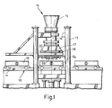
- a mold filling device 14 for supplying molding material to a mold box 12 f standing between those frame columns 13 is arranged above vertical movement paths 10 for transport pallets 11 of mold boxes 12 between vertical frame columns 13.
- the mold filling device 14 contains a filling or ventilation cylinder 16 between an upper inlet funnel 15 for the molding material and a lower shooting hood 17. That shooting hood 17 widens downwards to one its deepest cross section spanning form filling plate 18, which is fixed by means of screws 19 to an edge flange 20 of the shooting hood 17.
- the filling or ventilation cylinder 16 hangs with the interposition of a shut-off valve in the form of a - a flap 21 k - ring 21 with an upper cylinder collar 22 on a support flange 23 of that inlet funnel 15 and has a distance i to the cylinder collar 22 ah Cylinder wall 25 with its legs 26, 27 welded on channel profile 28, which is provided at the bottom with openings 30 closed by plugs 29 and - according to FIG. 3 - with tangential air inlet tubes 31.
- the annular space 3.3 delimited by the channel profile 28 is - in the selected exemplary embodiment - equipped with guide tools 34 which are curved in plan view, and its inner boundary formed by part of the cylinder wall 25 is provided with openings 36 which are spanned by an inner jacket 38 which is in the Area of those openings 36 is air-permeable, for example provided with slots 37.
- the cylinder wall 25 surrounds a lower channel profile 28 t of a corresponding configuration.
- the filling cylinder 16 equipped with that inner jacket 38 ends upwards in a head ring 40 adjoining a sealing element 39 and downwards on a connecting ring 41, which hold screws 19 ′ on a cantilever ring 44 of the shooting hood 17.
- a hood cone 50 of the shooting hood 17 carries bellows elements 51 on the inside, which are tightly connected to and in the hood cone 50 by clamping screws 52 Interiors 54 at least one air supply 55 ends.
- Such an air-filling bellows element is designated 51 t in FIG. 4, left.
- another bellows element 57 protrudes from the mold filling plate 18 at least into the interior 59 of the hood cone 50 and is supplied with air, for example, through a line 60 of the mold filling plate 18, in order to transfer it to the contour indicated at 57 t to become.
- vented molding material is suddenly pressed downwards through the ventilation cylinder 16 to the mold box 12 f .
- the air / molding material mixture is homogenized on its way in the direction of the arrow x.
- the air supply to the upper and lower channel profile 28 are switched at intervals to ensure that even hard-flowing molding materials flow as homogeneously as possible and thus - as I said suddenly - get into the mold cavity 12 f present in the mold or core box. This is made possible by those mold plate nozzles 64 of the mold fill plate 18.
- the mold plate nozzles 64 form in the existing one Molded air channels, a few of which are indicated at K in Fig. 4, right.
- the molding material F surrounding these channels K determines a useless dead volume. If the molding material is accidentally broken off in this dead space, mold defects can occur. This is prevented by those bellows elements 51, 57 which are free of air before the filling process described and after which air is applied to them; As the bellows volume increases, the molding material F located in the interior 59 of the hood cone 50 is pushed through the bellows elements 51 from the side toward the central axis M.
- the channels K are eliminated, and, on the other hand, when those side bellows elements 51 are vented, a cavity is created between them and the molding material guided to the center, into which a new molding material runs, which after the next firing operation presses to the central axis M in the manner described and so the mold plate nozzles 64 is placed in front of the next shooting process.
- the central bellows element 57 t is intended to support the destruction of those channels K, so to help concentrate the molding material F remaining in the interior '59 after the shooting process.
- the lateral bellows elements 51 have the additional task of forming displacers depending on the degree of inflation, thanks to which a controlled reduction in the interior 59 of the hood cone 50 can take place. In this way, dead volume is avoided and the residence time of the molding material in the interior 59 is influenced; the choice of the degree of filling remains variable within wide limits.
Landscapes
- Engineering & Computer Science (AREA)
- Mechanical Engineering (AREA)
- Casting Devices For Molds (AREA)
Applications Claiming Priority (2)
| Application Number | Priority Date | Filing Date | Title |
|---|---|---|---|
| DE19853506752 DE3506752A1 (de) | 1985-02-26 | 1985-02-26 | Verfahren und vorrichtung zum fuellen eines formkastens o.dgl. gefaesses mit formstoff |
| DE3506752 | 1985-02-26 |
Publications (2)
| Publication Number | Publication Date |
|---|---|
| EP0193140A2 true EP0193140A2 (fr) | 1986-09-03 |
| EP0193140A3 EP0193140A3 (fr) | 1987-05-20 |
Family
ID=6263600
Family Applications (1)
| Application Number | Title | Priority Date | Filing Date |
|---|---|---|---|
| EP86102321A Withdrawn EP0193140A3 (fr) | 1985-02-26 | 1986-02-22 | Procédé et dispositif pour remplir un châssis de moulage ou un réservoir semblable de matière de moulage |
Country Status (3)
| Country | Link |
|---|---|
| EP (1) | EP0193140A3 (fr) |
| JP (1) | JPS61195732A (fr) |
| DE (1) | DE3506752A1 (fr) |
Cited By (2)
| Publication number | Priority date | Publication date | Assignee | Title |
|---|---|---|---|---|
| EP0783944A1 (fr) * | 1996-01-12 | 1997-07-16 | Gebrüder Netzsch Maschinen- und Anlagenbau GmbH | Procédé et dispositif pour alimenter un moule de presse avec un matériau pulvérulent |
| EP0904871A1 (fr) * | 1996-06-28 | 1999-03-31 | Sintokogio, Ltd. | Méchanisme de tirage de sable de fonderie en machines de moulage |
Families Citing this family (2)
| Publication number | Priority date | Publication date | Assignee | Title |
|---|---|---|---|---|
| CN106077480A (zh) * | 2016-07-29 | 2016-11-09 | 安徽帝博工艺美术品制造有限公司 | 一种淋沙机 |
| CN106363142B (zh) * | 2016-12-05 | 2018-10-12 | 攀枝花市蓝天锻造有限公司 | 射芯机 |
Family Cites Families (4)
| Publication number | Priority date | Publication date | Assignee | Title |
|---|---|---|---|---|
| GB1467804A (en) * | 1974-07-12 | 1977-03-23 | Lamb Ltd G | Blow tubes for the manufacture of foundry cores and other articles of granular or powdered material |
| US3999592A (en) * | 1975-04-21 | 1976-12-28 | The Quaker Oats Company | Apparatus and method for manufacturing cores and molds with static mixer stage |
| DE2727297C3 (de) * | 1976-06-25 | 1980-07-10 | Georg Fischer Ag, Schaffhausen (Schweiz) | Verfahren und Einrichtung zum Herstellen von Gießereisandformen |
| JPS6048261B2 (ja) * | 1979-07-11 | 1985-10-26 | 株式会社豊田自動織機製作所 | 鋳型造型方法 |
-
1985
- 1985-02-26 DE DE19853506752 patent/DE3506752A1/de not_active Ceased
-
1986
- 1986-02-22 EP EP86102321A patent/EP0193140A3/fr not_active Withdrawn
- 1986-02-26 JP JP61041330A patent/JPS61195732A/ja active Pending
Cited By (2)
| Publication number | Priority date | Publication date | Assignee | Title |
|---|---|---|---|---|
| EP0783944A1 (fr) * | 1996-01-12 | 1997-07-16 | Gebrüder Netzsch Maschinen- und Anlagenbau GmbH | Procédé et dispositif pour alimenter un moule de presse avec un matériau pulvérulent |
| EP0904871A1 (fr) * | 1996-06-28 | 1999-03-31 | Sintokogio, Ltd. | Méchanisme de tirage de sable de fonderie en machines de moulage |
Also Published As
| Publication number | Publication date |
|---|---|
| DE3506752A1 (de) | 1986-08-28 |
| EP0193140A3 (fr) | 1987-05-20 |
| JPS61195732A (ja) | 1986-08-30 |
Similar Documents
| Publication | Publication Date | Title |
|---|---|---|
| EP0393315B1 (fr) | Procédé pour mouler par injection des pièces en matière plastique remplies de liquide et appareil pour la réalisation du procédé | |
| DE2644198C2 (de) | Schäumform zum Herstellen von geschäumten Formkörpern | |
| EP1123189B2 (fr) | Machine de moulage par injection et procede de production de pieces moulees par injection en forme d'enveloppes, notamment de preformes | |
| EP0311875A2 (fr) | Procédé et appareil pour fabriquer des articles multicouches | |
| DE10032269A1 (de) | Verfahren und Vorrichtung zur Verringerung von Nebenprodukten bei der Vermischung von Eduktströmen | |
| DE2332948C2 (de) | Verfahren und Vorrichtung zum Mischen von teilchenförmigen Feststoffen | |
| DE19835189A1 (de) | Vorrichtung zur kontinuierlichen Herstellung von nahtlosen Kunststoffrohren | |
| EP1232003A2 (fr) | Dispositif de revetement de particules | |
| DE1921048A1 (de) | Vorrichtung und Verfahren zum Herstellen von Sandformteilen | |
| DE2510804A1 (de) | Vorrichtung zur herstellung von extrudierten schlauchfoermigen thermoplastischen kunststoffilmen | |
| DE3603108A1 (de) | Vorrichtung zum herstellen von formlingen aus aufgeschaeumtem kunststoff | |
| DE1233571B (de) | Verfahren und Vorrichtung zum Durchfuehren plastischen Materials von einer Plastifiziereinrichtung durch einen Durchflusskopf zu einer Duese zum Auspressen eines Stranges, insbesondere zum Herstellen eines Hohlkoerpers aus thermoplastischem Kunststoff nach dem Blasverfahren | |
| EP0788869A1 (fr) | Procédé de fabrication d'un tube à paroi épaisse en polyéthylène | |
| DE3873299T2 (de) | Verfahren und vorrichtung zum schneiden von bahnfoermigem material. | |
| DE60301855T2 (de) | Verfahren und Vorrichtung zur Herstellung von Gusskernen | |
| EP0193140A2 (fr) | Procédé et dispositif pour remplir un châssis de moulage ou un réservoir semblable de matière de moulage | |
| DE1558108B1 (de) | Verfahren und Vorrichtung zur Herstellung von Sandkernen und Sandformen fuer Giessereizwecke | |
| DE3026822A1 (de) | Vorrichtung zum herstellen eines schlauchfoermigen stranges aus thermoplastischem kunststoff | |
| DE69022576T2 (de) | Verfahren und Vorrichtung zum Spritzgiessen mit direktem Angusssystem. | |
| DE2403199C3 (de) | Verfahren und Vorrichtung zur Sandzufuhr und zur Sandverdichtung bei Formenschießmaschinen | |
| DE2210099A1 (de) | Verfahren und vorrichtung zur ausformung von gegenstaenden aus waermehaertenden werkstoffen, insbesondere von fahrzeugluftreifen | |
| DE69120829T2 (de) | Verfahren und vorrichtung zur spätzugabe teilchenförmiger legierungen beim giessen von metallschmelzen | |
| DE3010694A1 (de) | Formmaschine | |
| DE2923271A1 (de) | Giesserei-formmaschine | |
| DE69229058T2 (de) | Verfahren zum blasformen von rohrfoermigen behaeltern |
Legal Events
| Date | Code | Title | Description |
|---|---|---|---|
| PUAI | Public reference made under article 153(3) epc to a published international application that has entered the european phase |
Free format text: ORIGINAL CODE: 0009012 |
|
| AK | Designated contracting states |
Kind code of ref document: A2 Designated state(s): AT BE CH DE FR GB IT LI LU NL SE |
|
| PUAL | Search report despatched |
Free format text: ORIGINAL CODE: 0009013 |
|
| AK | Designated contracting states |
Kind code of ref document: A3 Designated state(s): AT BE CH DE FR GB IT LI LU NL SE |
|
| 17P | Request for examination filed |
Effective date: 19870825 |
|
| STAA | Information on the status of an ep patent application or granted ep patent |
Free format text: STATUS: THE APPLICATION IS DEEMED TO BE WITHDRAWN |
|
| 18D | Application deemed to be withdrawn |
Effective date: 19880830 |
|
| RIN1 | Information on inventor provided before grant (corrected) |
Inventor name: KLEIN, OTTO, DIPL.-KAUF. Inventor name: MUELLER-SPAETH, GERHARD |