EP0193401B1 - Flüssigkristall-Projektionsanzeigevorrichtung - Google Patents
Flüssigkristall-Projektionsanzeigevorrichtung Download PDFInfo
- Publication number
- EP0193401B1 EP0193401B1 EP86301406A EP86301406A EP0193401B1 EP 0193401 B1 EP0193401 B1 EP 0193401B1 EP 86301406 A EP86301406 A EP 86301406A EP 86301406 A EP86301406 A EP 86301406A EP 0193401 B1 EP0193401 B1 EP 0193401B1
- Authority
- EP
- European Patent Office
- Prior art keywords
- liquid crystal
- voltage
- voltage level
- display device
- stable
- Prior art date
- Legal status (The legal status is an assumption and is not a legal conclusion. Google has not performed a legal analysis and makes no representation as to the accuracy of the status listed.)
- Expired - Lifetime
Links
Images


Classifications
-
- H—ELECTRICITY
- H04—ELECTRIC COMMUNICATION TECHNIQUE
- H04N—PICTORIAL COMMUNICATION, e.g. TELEVISION
- H04N5/00—Details of television systems
- H04N5/74—Projection arrangements for image reproduction, e.g. using eidophor
- H04N5/7416—Projection arrangements for image reproduction, e.g. using eidophor involving the use of a spatial light modulator, e.g. a light valve, controlled by a video signal
- H04N5/7441—Projection arrangements for image reproduction, e.g. using eidophor involving the use of a spatial light modulator, e.g. a light valve, controlled by a video signal the modulator being an array of liquid crystal cells
-
- G—PHYSICS
- G09—EDUCATION; CRYPTOGRAPHY; DISPLAY; ADVERTISING; SEALS
- G09F—DISPLAYING; ADVERTISING; SIGNS; LABELS OR NAME-PLATES; SEALS
- G09F9/00—Indicating arrangements for variable information in which the information is built-up on a support by selection or combination of individual elements
- G09F9/30—Indicating arrangements for variable information in which the information is built-up on a support by selection or combination of individual elements in which the desired character or characters are formed by combining individual elements
- G09F9/35—Indicating arrangements for variable information in which the information is built-up on a support by selection or combination of individual elements in which the desired character or characters are formed by combining individual elements being liquid crystals
Definitions
- the present invention relates to a projection type liquid crystal display device. More particularly, it relates to such a device which is capable of writing and erasing an image only by application of voltage and of displaying the information from a remote place and which is compact and produces a bright display image at a projection area even in bright surroundings.
- a display device is suitable for use at conferences, in education, and for public notices such as in theaters, music halls, department stores, railway stations, airport lobbies, etc.
- CTR cathode ray tubes
- laser light writing projection type liquid crystal display devices and CRT writing projection type liquid crystal display devices
- CRT writing projection type liquid crystal display devices have been used as projection type display devices for relatively bright rooms (see IBM. J. Res. Develop. Vol. 26, No. 2, pp 177-185 (1982); Hughes, SID 79 DIGEST pp 22-23 (1979).
- These devices are of the scanning type.
- Also known are overhead projectors (OHP) which project an original directly onto a screen.
- OHP overhead projectors
- Projection type CRT's have projection devices built in so that an image formed on a CRT display surface is projected onto a screen.
- Laser light writing projection type liquid crystal display devices project onto a screen an image formed in a liquid crystal panel by changing alignment states thereof by heat from the laser light.
- CRT writing projection type liquid crystal display devices comprise a liquid crystal panel comprising a laminate of a liquid crystal layer and a photoconductive layer between electrodes. A CRT irradiates the photoconductive layer with an image like light to change the voltage applied to the liquid crystal layer so that an image corresponding to the irradiated light is formed in the liquid crystal layer, which image is projected onto a screen.
- OHP's simply project an image formed on a transparent or translucent sheet with an opaque colorant onto a screen by white light.
- Projection type CRT's are essentially light emitters and therefore cannot use a light source for projection having a large quantity of light, such as a halogen lamp, resulting in a dark projected image on a screen. Since it projects an image formed on an image face of a CRT, the whole device becomes large so that it ordinarily has to be used in a fixed place, and is not portable.
- Laser light writing projection type liquid crystal display devices have advantages that light sources emitting a large quantity of light can be used for projection and both reflection and transmission type projections can be done so that the projected image is bright. These devices however use writing laser light providing heat to a liquid crystal to cause thermally induced phase transition and form an image, by which a display is attained. This mechanism necessitates such electric power being applied to the liquid crystal. Further, because the heat necessary for causing the phase transition of a liquid crystal is supplied by light, the output of laser light must also be large and a light source such as an argon laser is necessary, which makes it impossible to make the device compact.
- CRT writing projection type liquid crystal display devices have a powerful light source, though it is smaller than that of the above laser light writing devices. Since an image is transferred from a faceplane of a CRT to a liquid crystal panel, the faceplane of the CRT or the original image cannot be large. As a result, the image must be magnified by providing a large distance from the liquid crystal panel to a projection screen and,therefore, the brightness of the image on the screen is not sufficient.
- OHP's have been widely used in conferences of small numbers of participants since they have advantages of light weight, compactness and low costs, can display an original image directly on a screen, and allow writing on the original sheet in situ with an oil pen. Further, the original sheet usually is of an A4 size, so not that large a magnification is necessary and the image on the screen is bright enough to see even in a bright room.
- preparation of OHP sheets is necessary and fine lettering is required depending on the nature of the conference, etc. OHP sheets once made cannot be modified during display. If there are a large number of OHP sheets, carrying them and changing sheets in the OHP are troublesome.
- this invention provides a projection-type liquid crystal display device, comprising; a first transparent substrate (13); a second transparent substrate (14) substantially in parallel with the first transparent substrate:
- this invention provides a display method using a liquid crystal panel (1) containing signal and scanning electrodes (X 1 , X 2 ; Y 1 , Y 2 ) and image elements formed of a cholesteric-nematic phase transition type liquid crystal with positive dielectric anisotropy (11, 12) held in an enclosed space, the cholesteric-nematic phase transition type liquid crystal comprising a mixture of a nematic liquid crystal and a chiral nematic liquid crystal, having a high transparency nematic phase (11) in a first stable optical state and a low transparency cholesteric phase (12) in a second stable optical state and having an applied voltage-transparency hysteresis with an extended width, comprising the steps of:
- the display device of this invention may have various types of input means and optical or projection systems.
- the display device of this invention may be used in conjunction with a remote communication system, or an electronic conference system enabling conferences between remote places through telephone cables or radio systems, wherein a projection type liquid crystal display device is used for display in each place.
- Figure 1 illustrates an example of the constitution of a projection type liquid crystal display device according to the present invention.
- reference numeral 1 denotes a liquid crystal panel, 2 a light source, 3, 4, and 5 lenses, 6 and 7 filters, 8 a screen, and 9 and 10 viewers.
- An image formed on the liquid crystal panel 1 is projected onto the screen 8 by an optical system composed of the light source 2, the lenses 3 to 5 and the filters 6 and 7 to effect a display.
- a liquid crystal panel 1 comprises a cholesteric-nematic phase transition type liquid crystal with positive dielectric anisotropy 11 or 12 sealed between transparent substrates 13 and 14 having transparent electrodes 15 and 16 respectively arranged in the form of a simple X-Y matrix.
- the electrodes 15 and 16 may be constituted from segments.
- the liquid crystal 11 if the liquid crystal 11 is nematic phase, the liquid crystal 11 allows incident light to pass through it so that light from a light source 2 is condensed by an optical system onto a screen 8 and the screen 8 becomes bright.
- Fig. 2A if the liquid crystal 11 is nematic phase, the liquid crystal 11 allows incident light to pass through it so that light from a light source 2 is condensed by an optical system onto a screen 8 and the screen 8 becomes bright.
- Fig. 1 if the liquid crystal 11 is nematic phase, the liquid crystal 11 allows incident light to pass through it so that light from a light source 2 is condensed by an optical system onto a screen 8 and the screen
- liquid crystal 12 if the liquid crystal 12 is cholesteric phase, the liquid crystal 12 scatters incident light so that light from a light source 2 is not condensed onto a screen 8 and the screen 8 becomes remarkably dark. Therefore, if portions of nematic and cholesteric phases are selectively (or in the form of an image) formed in the liquid crystal panel 1 by appropriately driving the electrodes 15 and 16, bright and dark portions are formed on the screen 8, which portions correspond to the above selective phase portions of the liquid crystal 11 and 12. Thus, an image, a latent image, formed on the liquid crystal panel 1 is projected onto the screen 8 and the display is attained.
- This liquid crystal display using the transmission/bright-scattering/dark relationship or phenomenon provides advantages that a bright display as a whole is possible and contrast is high.
- any liquid crystal which exhibits cholesteric-nematic phase transition and has positive dielectric anisotropy can be used in a projection type liquid crystal display device according to the present invention.
- a liquid crystal is a mixture of a nematic liquid crystal and a cholesteric or chiral nematic liquid crystal.
- An example of an ethane-system nematic liquid crystal is
- a mixture of ethane-system nematic and chiral nematic liquid crystals is the most preferable. Further details can be seen in the specifications of Japanese Patent Application Nos. 59-35114, 59-107404, 59-180633,etc.
- a voltage 2V d is applied between each signal electrode (X electrode) and each scanning electrode (Y electrode) to change the entire liquid crystal into an initial state or H state.
- the liquid crystal is in the nematic phase and all image elements are transparent, so that about 90% of light from a light source is condensed by lenses and reaches a screen.
- transparent electrodes such as ITO (indium tin oxide) and absorption or scattering by the liquid crystal is almost negligible. Therefore, if transparent conductive materials such as ITO are improved in the future, brightness of an image on a screen is expected to become higher.
- V L the voltage applied to image elements in the liquid crystal panel where writing is to be conducted
- V L the liquid crystal becomes the cholesteric phase, F 0 state.
- a voltage of above V L normally 2 Vd or Vd, is still applied to image elements in the liquid crystal panel where writing is not to be conducted.
- the liquid crystal is in the nematic phase, H or H' state.
- a voltage of Vd is applied to all image elements. The above operation is repeated on every scanning line to conduct writing in the liquid crystal panel.
- these two states i.e., F and H' states, are maintained stably if application of the voltage Vd thereto is continued.
- a display is established.
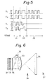
- Figures 4 and 5 illustrate an example of a 2 x 2 simple X-Y matrix arrangement of electrodes and a voltage waveform diagram for driving the electrodes.
- the electrodes X 1 and X 2 are signal electrodes and the electrodes Y 1 and Y 2 are scanning electrodes.
- the cross-hatched portions, or image elements, (X 1 , Y 1 ) and (X 2 , Y 2 ) are expected not to be written and the crossed portions, or image elements (X 1 , Y 2 ) and (X 2 , Y 1 ) are expected to be written.
- a voltage of 2 Vd is applied to all image elements to place them in an H state or nematic phase.
- a writing stage 22 application of voltage to the image elements (X 1 , Y 2 ) and (X 2 , Y 1 ) is stopped for a while, e.g., a time period of two pulses in Fig. 5, while a voltage of 2Vd or Vd is applied to the image elements (X 1 , Y 1 ) and (X 2 , Y 2 ).
- a voltage of 2Vd or Vd is applied to the image elements (X 1 , Y 1 ) and (X 2 , Y 2 ).
- the image elements (X 1 , Y 2 ) and (X 1 , Y 2 ) become the F 0 state or cholesteric phase.
- the image elements (X 1 , Y 1 ) and (X 2 , Y 2 ) continue in the nematic phase or H or H' state.
- the image elements (X 1 , Y 2 ) and (X 2 , Y 1 ) enter and continue to be in the F state or cholesteric phase, and the image elements (X 1 , Y 1 ) and (X 2 , Y 2 ) enter and continue to be in the H' state or nematic phase.
- a writing image comprising the image elements (X 1 , Y 2 ) and (X 2 , Y 1 ) is formed in a liquid crystal panel.
- the number of scanning lines is not limited.
- the liquid crystal When a liquid crystal is in a light scattering state, the liquid crystal is in the cholesteric phase having a helical structure between electrodes.
- the helical axes thereof are perpendicular or almost perpendicular to incident light so that the incident light is scattered by the helical structure of the liquid crystal of the chloesteric phase.
- This driving method allows partial rewriting of an image.
- this driving method allows reversion between the cholesteric phase and nematic phase, that is, for example, the letter portion is displayed by the nematic phase (transmission or bright) and the background is displayed by the cholesteric phase (scattering or dark), and also allows negative-positive reversion only in a desired portion of the display.
- RGBD Red, Green and Blue
- a latent image formed in the liquid crystal panel 1 is projected onto the screen 8 by modifying light from the light source 2 to parallel rays by the convex lens 3, passing them through the liquid crystal panel 1, condensing them by the convex lens 4, and then expanding them by the concave lens 5 onto the screen 8.
- an image on the screen 8 can be seen from either the front side 9 or rear side 10 of the screen 8.
- the reference numerals 6 and 7 denote filters, an IR cutting cold filter for preventing penetration of heat into the liquid crystal panel 1 and a UV cutting filter for preventing photo-decomposition of the liquid crystal in the panel 1 being preferably inserted into one or both filters.
- the optical system may be varied and is not limited to the above one. Further, the optical system may be the reflection projection type.
- Figure 6 illustrates an example of such an optical system.
- reference numeral 31 denotes a liquid crystal panel, 32 a light source, 33 a lens, 34 a mirror, 35 a screen, 36 a filter, and 37 and 38 viewers.
- light from the light source 32 is incident on the liquid crystal panel 31, passes through the liquid crystal panel 31, is reflected by the mirror 34, again passes through the liquid crystal panel 31 in the reverse direction, and is condensed onto the screen 35 by the condensing lens 33.
- the liquid crystal panel 31 has image elements where the liquid crystal is in the cholesteric phase, the light does not pass through the liquid crystal panel there and the light is not condensed to the corresponding portions on the screen 35 so that an image composed of bright and dark portions is formed on the screen 35.
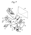
- a projection type liquid crystal display device can be driven by application of voltage alone. Therefore, for example, as seen in Fig. 7, a main display device 41 may be provided with an adapter 42 for remote communication such as a radio transmitting unit or an acoustic coupler 43 so that the contents of the display can be transmitted and received between remote places by means of telephone lines etc., whereby simultaneous display at remote places is enabled and a display device suitable for electronic conference systems is provided.
- an adapter 42 for remote communication such as a radio transmitting unit or an acoustic coupler 43 so that the contents of the display can be transmitted and received between remote places by means of telephone lines etc., whereby simultaneous display at remote places is enabled and a display device suitable for electronic conference systems is provided.
- the display device By providing the display device with a floppy disc unit 44, indirect mechanical input from a separate word processor, microcomputer, etc. is possible and a large quantity of display data can be stored making storing and carrying convenient.
- a keyboard 46 may be provided. If a keyboard 46 is provided, the display conducted by a floppy disc, etc., can be modified, or all or a part of the display may be presented with positive-negative reversion. By providing the display device with a character reader 47 or a means for hand writing input 48, display can be conducted from handwritten drafts, etc.
- reference numeral 49 denotes a screen and 50 an audio instrument such as a microphone or a loud speaker.
- a projection type liquid crystal display device has advantages of portability and low cost since it is basically the same size as or smaller than a conventional OHP. This, however, does not exclude using the device for a large-scale display by increasing the information contents of the liquid crystal panel.
- FIG 8 illustrates a projection type liquid crystal display according to the present invention using an OHP or the like.
- a main OHP 51 may be a conventional OHP or a similar one. If a liquid crystal panel 52 is placed at an original setting portion of the main OHP 51 in place of a draft paper and driven, e.g., by a driving unit 53 such as a floppy disc unit 53, an image is formed on the liquid crystal panel 52 in accordance with information stored in the floppy disc and projected onto a screen.
- a liquid crystal panel 52 may be incorporated into or removably attached to the main OHP 51.
- Figure 9 illustrates a public notice board, useful, for example, at an airport lobby.
- reference numeral 61 denotes a liquid crystal panel
- 62 a box including a light source and an optical system for projection
- 63 a screen. Projection is made to the screen 63, for example, of about 100 inch (2.54 m) size, from the back of the screen 63 to a viewer 64.
- This display device can be compact but allows bright display with a large quantity of information and easy display or modification of an image in different places or even by remote control.
- ITO transparent electrode
- the mixed nematic liquid crystals were made by mixing ethane-system and ester-system liquid crystals as major components with biphenyl-system, pyrimidine-system, and dioxane-system liquid crystals being present in minor amount.
- the chiral nematic liquid crystal was 2-methylbutylcyanobiphenyl.
- This liquid crystal panel was placed on a commercially available 650 W OHP and driven by a driving method as described with reference to Figs. 3 to 5.
- imaging or displaying could be effected at a speed of 384 ms/image face, or a total of 64 ms for initialization and 4 ms x 80 lines for writing per image face.
- writing or displaying of each letter could be done at a speed of 92 ms/letter, or a total of 64 ms for initialization and 4 ms x 7 lines for writing per letter, assuming alpha numeric letters constituted by 5 x 7 dots.
- an image having an effective image area of 9 cm x 6 cm formed in the liquid crystal panel was enlarged to an image having a size of about 120 cm x 80 cm on the screen.
- the projected image or display was as bright as that obtained by an OHP, in an office having normal lighting brightness.
Landscapes
- Chemical & Material Sciences (AREA)
- Crystallography & Structural Chemistry (AREA)
- Engineering & Computer Science (AREA)
- Physics & Mathematics (AREA)
- General Physics & Mathematics (AREA)
- Theoretical Computer Science (AREA)
- Multimedia (AREA)
- Signal Processing (AREA)
- Liquid Crystal (AREA)
- Liquid Crystal Display Device Control (AREA)
- Devices For Indicating Variable Information By Combining Individual Elements (AREA)
Claims (18)
- Flüssigkristallanzeigevorrichtung des Projektionstyps mit:einem ersten transparenten Substrat (13);einem zweiten transparenten Substrat (14), das zu dem ersten transparenten Substrat im wesentlichen parallel ist;einem Flüssigkristall des cholesterisch-nematischen Phasenübergangstyps, der eine positive dielektrische Anisotropie (11, 12) hat und zwischen den ersten und zweiten transparenten Substraten (13 und 14) angeordnet ist;einem Abdichtungsmittel, das den Flüssigkristall zwischen den ersten und zweiten transparenten Substraten (13 und 14) abdichtet, welche ersten und zweiten transparenten Substrate und welches Abdichtungsmittel einen umschlossenen Raum bilden, wobei die ersten und zweiten transparenten Substrate jeweils eine Innenfläche haben, die dem umschlossenen Raum zugewandt ist;einem ersten transparenten Elektrodenmittel (15), das auf der Innenfläche des ersten transparenten Substrates (13) gebildet ist;einem zweiten transparenten Elektrodenmittel (16), das auf der Innenfläche des zweiten transparenten Substrates (14) gebildet ist; undeinem Steuermittel für die selektive Anwendung einer vorbestimmten Sequenz von Spannungspegeln zwischen den ersten und zweiten Elektroden, um den Flüssigkristall an selektierten nichtadressierten Abschnitten der Vorrichtung in einen stabilen Lichtstreuzustand zu versetzen und den Flüssigkristall an den übrigen adressierten Abschnitten der Vorrichtung in einen stabilen Lichtdurchlaßzustand zu versetzen, dadurch gekennzeichnet, daß die vorbestimmte Sequenz von Spannungspegeln einen ersten Spannungspegel umfaßt, einen zweiten, mittleren Spannungspegel, der höher als der erste Spannungspegel ist, und einen dritten Spannungspegel, der höher als der zweite, mittlere Spannungspegel ist, so daß dann, wenn der erste, niedrige Spannungspegel zwischen den Elektroden angewendet wird, der Flüssigkristall in der Vorrichtung einen fokal-konischen Zustand (F) annimmt, dem eine cholesterische Phase des Flüssigkristalls zugeordnet ist, in der Licht, das auf die Vorrichtung einfällt, in dem Flüssigkristall gestreut wird, welcher fokal-konische Zustand bei dem ersten Spannungspegel stabil ist;wenn der Spannungspegel von dem ersten, niedrigen Spannungspegel auf den zweiten, mittleren Spannungspegel erhöht wird, der Flüssigkristall in dem stabilen fokal-konischen Zustand bleibt;wenn der Spannungspegel von dem zweiten, mittleren Spannungspegel auf den dritten, höheren Spannungspegel erhöht wird, der Flüssigkristall in der Vorrichtung einen homöotropen Zustand (H) annimmt, dem eine nematische Phase des Flüssigkristalls zugeordnet ist, in der Licht, das auf die Vorrichtung einfällt, durch den Flüssigkristall durchgelassen wird, welcher homöotrope Zustand bei dem dritten Spannungspegel stabil ist;wenn die Spannung von dem dritten, höheren Spannungspegel auf den zweiten, mittleren Spannungspegel reduziert wird, der Flüssigkristall in dem stabilen homöotropen Zustand bleibt, so daß dem zweiten, mittleren Spannungspegel sowohl ein stabiler durchlassender Zustand (H') als auch ein stabiler streuender Zustand (F) zugeordnet ist, wodurch die Vorrichtung bei diesem Spannungspegel eine bistabile Durchlässigkeit aufweist;und, wenn die Spannung von der zweiten, mittleren Spannung, bei der der Flüssigkristall in dem stabilen homöotropen Zustand ist, auf den ersten, niedrigen Spannungspegel reduziert wird, der Flüssigkristall in den stabilen fokal-konischen Zustand (F) zurückkehrt,wodurch die Flüssigkristallvorrichtung angetrieben werden kann, um ein Bild zu erzeugen, das aus bistabilen cholesterischen (12) und nematischen (11) Phasen gebildet ist, die Licht, das auf sie einfällt, streuen bzw. durchlassen und die stabil beibehalten werden können, indem der Spannungspegel auf der zweiten, mittleren Spannung gehalten wird, welches Bild durch ein optisches System auf einen Projektionsbereich projizierbar ist.
- Fernkommunikationssystem mit einer Flüssigkristallanzeigevorrichtung des Projektionstyps nach Anspruch 1 und einem Mittel (42 oder 43) zum Übertragen von Daten von einem entfernten Ort zu einem Antriebsmittel zum Erzeugen des Bildes auf der Vorrichtung.
- Elektronisches Konferenzsystem, das ein Konferieren zwischen entfernten Orten ermöglicht, mit einem Kommunikationsmittel (42 oder 45), das an jedem entfernten Ort angeordnet ist, zum Kommunizieren der Orte durch wenigstens eines von Telefonkabeln und Funksystemen; und Flüssigkristallanzeigevorrichtungen des Projektionstyps nach Anspruch 1, die jeweils mit dem Kommunikationsmittel operativ verbunden sind, wobei wenigstens eine Flüssigkristallanzeigevorrichtung zur Anzeige an jedem entfernten Ort verwendet wird.
- Anzeigevorrichtung nach Anspruch 1 oder in einem System nach Anspruch 2 oder 3, zusätzlich mit einer Lichtquelle (2) und einem optischen System (3, 4, 5, 6, 7) zum Projizieren des Bildes auf einen Projektionsbereich (8), dem die genannte Vorrichtung oder eine genannte Vorrichtung des Anzeigesystems zugeordnet ist.
- Overhead-Projektor (51), der eine Lichtquelle und eine Anzeigevorrichtung nach Anspruch 1 umfaßt.
- Anzeigevorrichtung nach Anspruch 4, bei der das optische System das Bild auf den Projektionsbereich (8) von derselben Seite wie jener eines Betrachters projiziert.
- Anzeigevorrichtung nach Anspruch 4, bei der das optische System das Bild auf den Projektionsbereich (8) von der einem Betrachter gegenüberliegenden Seite projiziert.
- Anzeigevorrichtung nach irgendeinem der Ansprüche 1, 4, 6 und 7, bei der eine Bildbeibehaltung der Flüssigkristalltafel durch kontinuierliche Anwendung einer vorbestimmten Spannung erfolgt.
- Anzeigevorrichtung nach irgendeinem der Ansprüche 1, 4 und 6 bis 8, bei der die Elektroden einfache X-Y-Matrixelektroden (15, 16) sind.
- Anzeigevorrichtung nach irgendeinem der Ansprüche 1, 4 und 6 bis 9, mit einer genannten Flüssigkristalltafel, die Elektroden des Segmenttyps (15, 16) hat.
- Anzeigevorrichtung nach irgendeinem der Ansprüche 1, 4 und 6 bis 10, bei der die Flüssigkristalltafel eine Kristalltafel des Durchlaßtyps (1) ist.
- Anzeigevorrichtung nach irgendeinem der Ansprüche 1, 4 und 6 bis 11, bei der die Flüssigkristallvorrichtung der Reflexionstyp (31, 34) ist.
- Anzeigevorrichtung nach einem der Ansprüche 1, 4 und 6 bis 12, die eine Tastatur (46) und/oder einen Leser für ein Speichermedium wie etwa eine Diskette (44) oder ein Magnetband und/oder einen Zeichenleser (47) und/oder einen Graphikleser (48) enthält, um Bilddaten vorzusehen.
- Anzeigevorrichtung nach einem der Ansprüche 1, 4 und 6 bis 13, ferner mit einem akustischen Koppler (43), der mit einem oder dem genannten Antriebsmittel zur Eingabe verbunden ist.
- Anzeigevorrichtung nach irgendeinem der Ansprüche 1, 4 und 6 bis 14, die mit einem Computer oder einem Wortprozessor (45) verbunden ist.
- Anzeigevorrichtung nach irgendeinem der Ansprüche 1, 4 und 6 bis 15, die mit einem Overhead-Projektor kombiniert ist.
- Anzeigeverfahren unter Verwendung einer Flüssigkristalltafel (1), die Signal- und Scanelektroden (X1, X2; Y1, Y2) enthält, und Bildelemente, die aus einem Flüssigkristall des cholesterisch-nematischen Phasenübergangstyps mit positiver dielektrischer Anisotropie (11, 12) gebildet sind, der in einem umschlossenen Raum gehalten wird, welcher Flüssigkristall des cholesterisch-nematischen Phasenübergangstyps ein Gemisch aus einem nematischen Flüssigkristall und einem chiral-nematischen Flüssigkristall umfaßt, eine nematische Phase (11) mit hoher Transparenz in einem ersten stabilen optischen Zustand hat und eine cholesterische Phase (12) mit niedriger Transparenz in einem zweiten stabilen optischen Zustand hat und eine Anwendungsspannung-Transparenz-Hysterese mit erweiterter Breite hat, das die folgenden Schritte umfaßt:(a) Anwenden einer ersten Spannung quer über jede Signalelektrode (X1, X2) und jede Scanelektrode (Y1, Y2), um die gesamte Flüssigkristalltafel (1) in den ersten stabilen optischen Zustand (H) zu versetzen;(b) Reduzieren der Spannung, die auf selektierte Bildelemente angewendet wird, wo ein Schreiben auszuführen ist, auf eine zweite Spannung und Halten dieser angewendeten Spannung für eine vorbestimmte Zeitperiode auf der zweiten Spannung, welcher zweite Spannungspegel niedrig genug ist, um den Flüssigkristall an den selektierten Abschnitten der Tafel in einen zweiten stabilen optischen Zustand (F) zu versetzen, während gleichzeitig eine dritte Spannung auf jene Bildelemente angewendet wird, die nicht zum Schreiben selektiert wurden, welche dritte Spannung hinreichend größer als die zweite Spannung ist, um solche nichtselektierten Bildelemente in dem ersten stabilen optischen Zustand (H) zu halten, und niedriger als die erste Spannung ist; und(c) Anwenden, nachdem Schritt (b) vollendet worden ist, der dritten Spannung auf die selektierten und die nichtselektierten Bildelemente, um die selektierten und nichtselektierten Bildelemente stabil in ihren jeweiligen zweiten und ersten stabilen Zuständen zu halten, solange die dritte Spannung angewendet wird.
- Anzeigeverfahren nach Anspruch 17, das unter Verwendung einer Flüssigkristallanzeigevorrichtung nach irgendeinem der Ansprüche 1, 4 und 6 bis 16 ausgeführt wird.
Applications Claiming Priority (3)
| Application Number | Priority Date | Filing Date | Title |
|---|---|---|---|
| JP37654/85 | 1985-02-28 | ||
| JP3765485 | 1985-02-28 | ||
| JP60037654A JPS61198270A (ja) | 1985-02-28 | 1985-02-28 | 投影形液晶表示装置、その方法および応用 |
Publications (3)
| Publication Number | Publication Date |
|---|---|
| EP0193401A2 EP0193401A2 (de) | 1986-09-03 |
| EP0193401A3 EP0193401A3 (de) | 1990-10-31 |
| EP0193401B1 true EP0193401B1 (de) | 2003-04-23 |
Family
ID=12503627
Family Applications (1)
| Application Number | Title | Priority Date | Filing Date |
|---|---|---|---|
| EP86301406A Expired - Lifetime EP0193401B1 (de) | 1985-02-28 | 1986-02-27 | Flüssigkristall-Projektionsanzeigevorrichtung |
Country Status (5)
| Country | Link |
|---|---|
| US (1) | US4812034A (de) |
| EP (1) | EP0193401B1 (de) |
| JP (1) | JPS61198270A (de) |
| CA (1) | CA1259686A (de) |
| DE (1) | DE3650781T2 (de) |
Families Citing this family (27)
| Publication number | Priority date | Publication date | Assignee | Title |
|---|---|---|---|---|
| JPS6160782A (ja) * | 1984-08-31 | 1986-03-28 | Fujitsu Ltd | 蓄積型液晶組成物 |
| JPS62127723A (ja) * | 1985-11-28 | 1987-06-10 | Agency Of Ind Science & Technol | 資料の投影表示装置 |
| GB8624985D0 (en) * | 1986-10-17 | 1986-11-19 | Emi Plc Thorn | Colour filter |
| US5278684A (en) * | 1986-12-11 | 1994-01-11 | Fujitsu Limited | Parallel aligned chiral nematic liquid crystal display element |
| US5227821A (en) | 1987-04-30 | 1993-07-13 | Nview Corporation | Liquid crystal display for projection systems |
| US5187510A (en) * | 1987-04-30 | 1993-02-16 | Nview Corporation | Liquid crystal display for projection systems |
| US5255029A (en) | 1987-04-30 | 1993-10-19 | Nview Corporation | Liquid crystal display for projection systems |
| JPS63276098A (ja) * | 1987-05-07 | 1988-11-14 | 富士通株式会社 | 投写型液晶表示装置 |
| US4928123A (en) * | 1987-06-16 | 1990-05-22 | Sharp Kabushiki Kaisha | Projection type liquid crystal display device |
| US5012274A (en) * | 1987-12-31 | 1991-04-30 | Eugene Dolgoff | Active matrix LCD image projection system |
| US5153568A (en) * | 1988-07-21 | 1992-10-06 | Proxima Corporation | Liquid crystal display panel system and method of using same |
| US5089810A (en) * | 1990-04-09 | 1992-02-18 | Computer Accessories Corporation | Stacked display panel construction and method of making same |
| US5302946A (en) * | 1988-07-21 | 1994-04-12 | Leonid Shapiro | Stacked display panel construction and method of making same |
| US4944578A (en) * | 1988-07-21 | 1990-07-31 | Telex Communications | Color graphic imager utilizing a liquid crystal display |
| US5499036A (en) * | 1988-07-21 | 1996-03-12 | Proxima Corporation | Display control apparatus and method of using same |
| USRE36654E (en) * | 1989-03-28 | 2000-04-11 | In Focus Systems, Inc. | Stacked LCD color display |
| US4917465A (en) * | 1989-03-28 | 1990-04-17 | In Focus Systems, Inc. | Color display system |
| US5050965A (en) * | 1989-09-01 | 1991-09-24 | In Focus Systems, Inc. | Color display using supertwisted nematic liquid crystal material |
| US5113332A (en) * | 1989-05-24 | 1992-05-12 | Morpheus Lights, Inc. | Selectable mechanical and electronic pattern generating aperture module |
| US5274484A (en) * | 1991-04-12 | 1993-12-28 | Fujitsu Limited | Gradation methods for driving phase transition liquid crystal using a holding signal |
| US5428417A (en) * | 1993-08-02 | 1995-06-27 | Lichtenstein; Bernard | Visual lecture aid |
| JP2963606B2 (ja) * | 1993-08-31 | 1999-10-18 | シャープ株式会社 | 液晶プロジェクション装置 |
| US5543832A (en) * | 1994-03-29 | 1996-08-06 | Laser Surge, Inc. | Video display system for projecting an image on to a tilted screen adjacent a surgical field |
| EP0675476B1 (de) * | 1994-03-30 | 1998-06-03 | Denso Corporation | Flüssigkristall-Anzeigevorrichtung |
| US20030142401A1 (en) * | 2002-01-25 | 2003-07-31 | Tominari Araki | Optical member |
| US20030151580A1 (en) * | 2002-02-11 | 2003-08-14 | Yao-Dong Ma | Motion video cholesteric displays |
| JP4968262B2 (ja) * | 2006-12-20 | 2012-07-04 | 富士通株式会社 | 液晶表示素子及びそれを用いた電子ペーパー |
Family Cites Families (16)
| Publication number | Priority date | Publication date | Assignee | Title |
|---|---|---|---|---|
| US3650603A (en) * | 1967-12-05 | 1972-03-21 | Rca Corp | Liquid crystal light valve containing a mixture of nematic and cholesteric materials in which the light scattering effect is reduced when an electric field is applied |
| CA931250A (en) * | 1970-06-19 | 1973-07-31 | A. Dir Hary | Imaging system |
| CH539315A (de) * | 1971-12-03 | 1973-07-15 | Bbc Brown Boveri & Cie | Informationsträger für Projektionszwecke |
| US3836243A (en) * | 1972-06-27 | 1974-09-17 | Bell Telephone Labor Inc | Liquid crystal display apparatus |
| JPS5650277B2 (de) * | 1973-03-27 | 1981-11-27 | ||
| US4060316A (en) * | 1975-02-25 | 1977-11-29 | Xerox Corporation | Imaging method |
| JPS5277699A (en) * | 1975-12-24 | 1977-06-30 | Seiko Epson Corp | Liquid crystal display device for waves projected on wall surface |
| US4368963A (en) * | 1978-06-29 | 1983-01-18 | Michael Stolov | Multicolor image or picture projecting system using electronically controlled slides |
| IL55032A (en) * | 1978-06-29 | 1984-05-31 | Stolov Michael | Color picture display system including electronically controlled slides |
| US4380372A (en) * | 1980-08-20 | 1983-04-19 | Kabushiki Kaisha Daini Seikosha | Phase transition mode liquid crystal display device |
| JPS5810721A (ja) * | 1981-07-14 | 1983-01-21 | Dainippon Printing Co Ltd | 液晶表示素子 |
| JPS5919924A (ja) * | 1982-07-24 | 1984-02-01 | Aporon Ongaku Kogyo Kk | 投影装置 |
| JPS5937533A (ja) * | 1982-08-26 | 1984-03-01 | Fuji Xerox Co Ltd | 画像投写装置 |
| JPS59131740A (ja) * | 1983-01-17 | 1984-07-28 | Hiroshi Nishida | エンスト防止装置 |
| JPS59151235A (ja) * | 1983-02-16 | 1984-08-29 | Matsushita Electric Ind Co Ltd | マイクロホン装置 |
| JPS59151236A (ja) * | 1983-02-17 | 1984-08-29 | Sanyo Electric Co Ltd | デイジタル加減算回路 |
-
1985
- 1985-02-28 JP JP60037654A patent/JPS61198270A/ja active Granted
-
1986
- 1986-02-27 DE DE3650781T patent/DE3650781T2/de not_active Expired - Fee Related
- 1986-02-27 CA CA000502922A patent/CA1259686A/en not_active Expired
- 1986-02-27 EP EP86301406A patent/EP0193401B1/de not_active Expired - Lifetime
-
1987
- 1987-12-21 US US07/139,164 patent/US4812034A/en not_active Expired - Lifetime
Also Published As
| Publication number | Publication date |
|---|---|
| DE3650781D1 (de) | 2003-05-28 |
| JPS61198270A (ja) | 1986-09-02 |
| DE3650781T2 (de) | 2004-03-04 |
| EP0193401A3 (de) | 1990-10-31 |
| CA1259686A (en) | 1989-09-19 |
| EP0193401A2 (de) | 1986-09-03 |
| US4812034A (en) | 1989-03-14 |
| JPH0473128B2 (de) | 1992-11-20 |
Similar Documents
| Publication | Publication Date | Title |
|---|---|---|
| EP0193401B1 (de) | Flüssigkristall-Projektionsanzeigevorrichtung | |
| EP0760965B1 (de) | Transportables computersystem mit zwei betrachtungsmoden | |
| US6414728B1 (en) | Image display system having direct and projection viewing modes | |
| US5680233A (en) | Image display systems having direct and projection viewing modes | |
| JP3371200B2 (ja) | 液晶表示装置の表示制御方法及び液晶表示装置 | |
| US5274484A (en) | Gradation methods for driving phase transition liquid crystal using a holding signal | |
| US7110052B1 (en) | Backlighting construction for use in computer-based display systems having direct and projection viewing modes of operation | |
| US4668049A (en) | Illumination for a scattering type liquid crystal display | |
| JP2000147454A (ja) | 液晶表示装置 | |
| JP2001133746A (ja) | 液晶表示装置 | |
| KR950035455A (ko) | 화상표시장치 | |
| TW574534B (en) | Liquid crystal display device | |
| AU2002334347A1 (en) | A visual display device, and a method for operating a visual display panel | |
| US6917391B1 (en) | Electro-optical backlighting panel for use in computer-based display systems and portable light projection device for use therewith | |
| US6724427B1 (en) | Driving a memory display in an image memory card | |
| JPS60213935A (ja) | オ−バヘツドプロジエクタ | |
| TWI423215B (zh) | 雙穩態顯示器之驅動方法 | |
| CN223986271U (zh) | 一种双向投影装置 | |
| JPS6269256A (ja) | 液晶表示装置 | |
| JPS62102232A (ja) | 光導電型液晶ライトバルブ | |
| Nelson et al. | Row-backlight, column-shutter display: a new display format | |
| KR100255822B1 (ko) | 화상 기억 액정표시소자 | |
| JP4032830B2 (ja) | 液晶表示素子および電子教科書 | |
| JP2002156620A (ja) | 液晶表示装置 | |
| JPH063640A (ja) | 液晶表示装置 |
Legal Events
| Date | Code | Title | Description |
|---|---|---|---|
| PUAI | Public reference made under article 153(3) epc to a published international application that has entered the european phase |
Free format text: ORIGINAL CODE: 0009012 |
|
| AK | Designated contracting states |
Kind code of ref document: A2 Designated state(s): CH DE FR GB LI |
|
| PUAL | Search report despatched |
Free format text: ORIGINAL CODE: 0009013 |
|
| AK | Designated contracting states |
Kind code of ref document: A3 Designated state(s): CH DE FR GB LI |
|
| 17P | Request for examination filed |
Effective date: 19901224 |
|
| 17Q | First examination report despatched |
Effective date: 19930503 |
|
| APCB | Communication from the board of appeal sent |
Free format text: ORIGINAL CODE: EPIDOS OBAPE |
|
| APCB | Communication from the board of appeal sent |
Free format text: ORIGINAL CODE: EPIDOS OBAPE |
|
| GRAG | Despatch of communication of intention to grant |
Free format text: ORIGINAL CODE: EPIDOS AGRA |
|
| GRAH | Despatch of communication of intention to grant a patent |
Free format text: ORIGINAL CODE: EPIDOS IGRA |
|
| GRAH | Despatch of communication of intention to grant a patent |
Free format text: ORIGINAL CODE: EPIDOS IGRA |
|
| GRAA | (expected) grant |
Free format text: ORIGINAL CODE: 0009210 |
|
| AK | Designated contracting states |
Designated state(s): CH DE FR GB LI |
|
| REG | Reference to a national code |
Ref country code: GB Ref legal event code: FG4D |
|
| REG | Reference to a national code |
Ref country code: CH Ref legal event code: EP |
|
| REF | Corresponds to: |
Ref document number: 3650781 Country of ref document: DE Date of ref document: 20030528 Kind code of ref document: P |
|
| PGFP | Annual fee paid to national office [announced via postgrant information from national office to epo] |
Ref country code: FR Payment date: 20040107 Year of fee payment: 19 |
|
| PGFP | Annual fee paid to national office [announced via postgrant information from national office to epo] |
Ref country code: GB Payment date: 20040224 Year of fee payment: 19 |
|
| ET | Fr: translation filed | ||
| PLBE | No opposition filed within time limit |
Free format text: ORIGINAL CODE: 0009261 |
|
| STAA | Information on the status of an ep patent application or granted ep patent |
Free format text: STATUS: NO OPPOSITION FILED WITHIN TIME LIMIT |
|
| PG25 | Lapsed in a contracting state [announced via postgrant information from national office to epo] |
Ref country code: LI Free format text: LAPSE BECAUSE OF NON-PAYMENT OF DUE FEES Effective date: 20040229 Ref country code: CH Free format text: LAPSE BECAUSE OF NON-PAYMENT OF DUE FEES Effective date: 20040229 |
|
| PGFP | Annual fee paid to national office [announced via postgrant information from national office to epo] |
Ref country code: DE Payment date: 20040311 Year of fee payment: 19 |
|
| 26N | No opposition filed |
Effective date: 20040126 |
|
| REG | Reference to a national code |
Ref country code: CH Ref legal event code: PL |
|
| PG25 | Lapsed in a contracting state [announced via postgrant information from national office to epo] |
Ref country code: GB Free format text: LAPSE BECAUSE OF NON-PAYMENT OF DUE FEES Effective date: 20050227 |
|
| PG25 | Lapsed in a contracting state [announced via postgrant information from national office to epo] |
Ref country code: DE Free format text: LAPSE BECAUSE OF NON-PAYMENT OF DUE FEES Effective date: 20050901 |
|
| APAH | Appeal reference modified |
Free format text: ORIGINAL CODE: EPIDOSCREFNO |
|
| GBPC | Gb: european patent ceased through non-payment of renewal fee |
Effective date: 20050227 |
|
| PG25 | Lapsed in a contracting state [announced via postgrant information from national office to epo] |
Ref country code: FR Free format text: LAPSE BECAUSE OF NON-PAYMENT OF DUE FEES Effective date: 20051031 |
|
| REG | Reference to a national code |
Ref country code: FR Ref legal event code: ST Effective date: 20051031 |