EP0193461A1 - Kalibrierverteiler von zylindrischen Elementen - Google Patents
Kalibrierverteiler von zylindrischen Elementen Download PDFInfo
- Publication number
- EP0193461A1 EP0193461A1 EP86400369A EP86400369A EP0193461A1 EP 0193461 A1 EP0193461 A1 EP 0193461A1 EP 86400369 A EP86400369 A EP 86400369A EP 86400369 A EP86400369 A EP 86400369A EP 0193461 A1 EP0193461 A1 EP 0193461A1
- Authority
- EP
- European Patent Office
- Prior art keywords
- diameter
- cylindrical elements
- station
- distributor
- plate
- Prior art date
- Legal status (The legal status is an assumption and is not a legal conclusion. Google has not performed a legal analysis and makes no representation as to the accuracy of the status listed.)
- Granted
Links
- 210000003456 pulmonary alveoli Anatomy 0.000 claims description 2
- 239000008188 pellet Substances 0.000 abstract description 41
- 239000000446 fuel Substances 0.000 abstract description 9
- 235000010603 pastilles Nutrition 0.000 description 4
- 241001080024 Telles Species 0.000 description 2
- 238000012550 audit Methods 0.000 description 2
- 230000003287 optical effect Effects 0.000 description 2
- 230000000149 penetrating effect Effects 0.000 description 2
- 239000002699 waste material Substances 0.000 description 2
- 206010041662 Splinter Diseases 0.000 description 1
- 230000000712 assembly Effects 0.000 description 1
- 238000000429 assembly Methods 0.000 description 1
- 230000006835 compression Effects 0.000 description 1
- 238000007906 compression Methods 0.000 description 1
- 239000006185 dispersion Substances 0.000 description 1
- 238000012423 maintenance Methods 0.000 description 1
- 238000012986 modification Methods 0.000 description 1
- 230000004048 modification Effects 0.000 description 1
- 230000002285 radioactive effect Effects 0.000 description 1
- 238000005245 sintering Methods 0.000 description 1
Images



Classifications
-
- B—PERFORMING OPERATIONS; TRANSPORTING
- B07—SEPARATING SOLIDS FROM SOLIDS; SORTING
- B07C—POSTAL SORTING; SORTING INDIVIDUAL ARTICLES, OR BULK MATERIAL FIT TO BE SORTED PIECE-MEAL, e.g. BY PICKING
- B07C5/00—Sorting according to a characteristic or feature of the articles or material being sorted, e.g. by control effected by devices which detect or measure such characteristic or feature; Sorting by manually actuated devices, e.g. switches
- B07C5/04—Sorting according to size
- B07C5/06—Sorting according to size measured mechanically
-
- G—PHYSICS
- G21—NUCLEAR PHYSICS; NUCLEAR ENGINEERING
- G21C—NUCLEAR REACTORS
- G21C17/00—Monitoring; Testing ; Maintaining
- G21C17/06—Devices or arrangements for monitoring or testing fuel or fuel elements outside the reactor core, e.g. for burn-up, for contamination
-
- Y—GENERAL TAGGING OF NEW TECHNOLOGICAL DEVELOPMENTS; GENERAL TAGGING OF CROSS-SECTIONAL TECHNOLOGIES SPANNING OVER SEVERAL SECTIONS OF THE IPC; TECHNICAL SUBJECTS COVERED BY FORMER USPC CROSS-REFERENCE ART COLLECTIONS [XRACs] AND DIGESTS
- Y02—TECHNOLOGIES OR APPLICATIONS FOR MITIGATION OR ADAPTATION AGAINST CLIMATE CHANGE
- Y02E—REDUCTION OF GREENHOUSE GAS [GHG] EMISSIONS, RELATED TO ENERGY GENERATION, TRANSMISSION OR DISTRIBUTION
- Y02E30/00—Energy generation of nuclear origin
- Y02E30/30—Nuclear fission reactors
Definitions
- the subject of the present invention is a distributor for calibrating cylindrical elements. It applies in particular, although in a nonlimiting manner, to the constitution of columns of radioactive fuel pellets.
- the "core" of a nuclear reactor includes a large number of combustible “needles” arranged in bundles in assemblies. They are the seat of a nuclear reaction, the basis of operation of the reactor.
- a combustible needle is shown in FIG. 1 in a simplified manner and in longitudinal section.
- the needle comprises a tubular sheath 2 closed at its ends by two plugs 4, 6 and in which a column of fuel pellets 8 is threaded.
- a needle comprises several tens of pellets 8.
- One of the objects of the invention is precisely to propose a calibrating distributor with a high rate of cylindrical elements such as fuel pellets, capable of constituting columns of cylindrical elements whose diameter is less than or equal to a maximum tolerated diameter and to discard nonconforming items.
- the means of the dispensing station for pushing the cylindrical elements comprise a movable frame guided in translation by a fixed slide of axis parallel to said aligned hole and alveolus, drive means allowing an alternating movement of the movable frame, a first end of a lever being pivotally mounted on the movable frame around an axis of rotation perpendicular to said axis of the slide, the other end of said lever being pivotally mounted at the end of a distributor piston, said piston being movable in translation and driven in an alternating movement, along an axis coincident with the cell and the hole aligned opposite the dispensing station.
- force limitation means are interposed in the assembly constituted by said lever and said distributor piston, said force limitation means not transmitting to the piston the movement of the movable frame when the piston is blocked by a cylindrical element with a diameter greater than the maximum tolerated diameter and trapped in a hole in the calibrator plate.
- the means of the ejection station comprise an ejector piston fixed to said movable frame parallel to the hole and to the cell aligned so as to penetrate successively into each of the holes of the calibrator plate and to eject the cylindrical elements wedged in said holes.
- the transfer barrel and the calibrating plate each have a toothed crown, the crowns of the barrel and of the plate forming a gear.
- a piece of tablet may remain at the bottom of one of the cells.
- a new step-daughter is introduced into this cell, it may protrude from the cell and be the cause of an operating incident of the calibrator distributor according to the invention.
- Another object of the invention is precisely to present a calibrating distributor comprising a device capable of detecting the excess lengths of the cylindrical elements and placed on the transfer barrel.
- This device comprises a free rotating plate whose wall opposite the barrel is located at a uniform distance from the inner end of each of the cells corresponding to a maximum authorized length of the cylindrical elements, this plate normally having a notch located opposite the feed station and means for detecting a rotational drive of said plate by a cylindrical element exceeding said maximum authorized length.
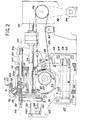
- the calibrating distributor firstly comprises a station for supplying cylindrical elements such as fuel pellets 8.
- This station notably includes a vibrating bowl and a feed chute 10 whose lower end is vertical.
- the internal diameter of the chute 10 is substantially equal to the diameter of the pellets 8, which allows them to appear vertically (that is to say that their axis of revolution is vertical at the lower end of said chute 10 .
- a transfer barrel 12 is arranged below the supply station.
- the barrel 12 is constituted by a frustoconical part with a half-angle at the top equal to 45 °.
- This barrel 12 is mounted in free rotation on a frame 14, the own axis of said barrel being coincident with an axis of rotation 16 screwed into said frame 14 at 45 ° on the horizontal.
- At least one bearing 18 allows the barrel 12 to rotate about the axis 16, the translation support being provided in the usual way.
- Equidistant cells 22, for example eight in number, are drilled in the barrel 12 so that their axis forms an angle of 45 ° with the axis of rotation 16 and is intersecting with this axis 16 at the same point.
- a cell 22 is vertical and coaxial with the feed chute 10, the cell 22 diametrically opposite then being horizontal.
- the cells 22 each consist of a cylindrical part 22a, of diameter substantially greater than the maximum diameter of the fuel pellets 8, arranged in alignment with the chute 10 when the cell is vertical and whose bottom 22b constitutes the inner end of the socket ( Figure 8).
- a hole 22c of diameter smaller than that of the pellets is drilled opening into said bottom coaxially with the part 22a. In this way, a pellet 8 can fall directly to the bottom 22b of the part 22a of the corresponding vertical cell 22.
- FIGS. 8 and 9 A device capable of detecting the surgeggers of the pellets is shown in FIGS. 8 and 9.
- This device comprises a cap 20 mounted in rotation on the end of the axis of rotation 16 and coming to cap the barrel 12.
- the cap 20 is conical in shape and follows the shape of the barrel 12, the wall 24 of said cap facing with respect to the barrel being located at a uniform distance from the bottom 22b of each of the cells 22. This distance corresponds to the maximum authorized length of the pellets 8.
- the cap 20 has a notch 26 capable of allowing the passage of a pellet of the chute 10 in the corresponding vertical socket 22. When the length of a pellet exceeds the maximum length authorized during the rotation of the barrel 12, this pellet rotates the cap 20 as it is shown in phantom in Figure 9.
- the rotation of the cap 20 is detected by a sensor 28 such as an optical sensor which triggers the stopping of the dispenser.
- a stop 30 is arranged in normal operation against the cap 20 to prevent its rotation in the opposite direction to the rotation of the barrel and so that the notch 26 is always correctly positioned.
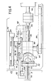
- a cylindrical calibrator plate 32 is mounted in horizontal rotation on the frame 14, substantially below the barrel 12.
- the plate 32 is fixed to one end of a horizontal shaft 34 whose guiding in rotation in the frame 14 is provided by two bearings 36, 38, the maintenance in translation being ensured by conventional devices.
- the other end of the shaft 34 is coupled to drive means 40.
- the calibrator plate 32 is pierced with holes, for example eight in number, equidistant and arranged horizontally with the same diameter.
- a sleeve 42 is secured in each of these holes and itself comprises a calibrated hole 44.
- this hole 4 4 comprises two frustoconical portions 44a, 44b, the portion 44a being facing the barrel 12, whose intersection 44c is located substantially in the middle of the hole 4 4 .
- the diameter of this intersection 44c constitutes the lower diameter of the hole 44, a diameter equal to a maximum authorized diameter of the fuel pellets 8.
- the calibrator plate is also arranged in such a way that each calibrated hole 44 can successively occupy a high position where said hole 44 is arranged opposite a corresponding horizontal recess 22. In this position called “distribution”, a calibrated hole 44 and a cell 22 are aligned along a horizontal axis 45 called “distribution”.
- a conical toothed crown 46 is formed on the wall of the calibrating plate 32 located on the side of the shaft 34. This crown 46 cooperates with a conical toothed crown 48 formed on the periphery of the barrel 12 so that they form a gear. This allows, for each rotation of an eighth of a turn of the plate 32 caused by the drive means 40, a corresponding rotation of an eighth of a turn of the barrel 12. Thus, each cell 22 and each calibrated hole 44 occupy sequentially the distribution position where they are aligned.
- a distributor piston 50 is mounted in horizontal sliding in the frame 14 coaxially with said distribution axis 45.
- the piston 50 comprises a first part 50a of larger diameter, sliding in a bore 52 of the frame, and a second part 50b sliding in a sleeve 54 fixed in the frame 1 4.
- the diameter of the second part 50b is slightly less than the diameter of the hole 22c (FIG. 8) of each cell 22.
- the piston 50 pushes the pellet through the calibrated hole 44 to a guide vee 56 disposed in alignment with said axis of distribution 45 and near the calibrator plate 32 (FIG. 7A).
- the length of the vee 56 is sufficient to allow the constitution of columns of fuel pellets, intended to be sheathed.
- Two cylindrical bars 58, 60 superimposed in a vertical plane, parallel to said distribution axis, are fixed in the lower part of the frame 14 by two vertical flanges 62, 64.
- the two bars 58, 60 serve as slides and supports for a movable frame 66.
- the movable frame 66 of generally planar and vertical shape, has in its lower part two bores 68, 70 in which the two bars 58 , 60 are threaded respectively.
- the movable frame 66 has in its upper part a notch 72 substantially in the shape of a U.
- Two rollers 74, 76 are mounted with horizontal pivoting, perpendicular to the axis of transfer, on the movable frame 66, on each side thereof. respectively and proximity of the opposite upper ends of the notch 72.
- Two cams 78, 80 of flat and ovoid shape are integral with a drive shaft 82 rotatably mounted in the frame 14, perpendicular to said transfer axis 45, and substantially in the middle of the notch 72 when the movable frame 66 is halfway between the two flanges 62, 64.
- This shaft 82 is located in the same horizontal plane as the two rollers 74, 76.
- the two cams 78, 80 are located on either side of the frame 66 and applied to the two rollers 74, 76 respectively.
- the cooperation of the two cams 78, 80 causes the movable frame 66 to perform an alternating movement, parallel to said transfer axis, when the drive shaft 82 rotates.
- the shaft 82 is driven in rotation by the drive means 40 which comprise a motor 84 driving a pulley 86 by a belt 88, this pulley 86 driving another pulley 87 secured to the drive shaft 82 by a belt 89. This is tensioned by a tensioner 90.
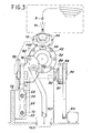
- a lever 92 is pivotally mounted on the frame 14 as shown in FIGS. 5 and 6.
- two legs 94, 96 project parallel and vertically from the frame 14 below the shaft 34 and on the side opposite to the calibrating plate 32.
- a support pin 98 is mounted to rotate freely perpendicularly to said transfer axis 45 on these two legs 94, 96, thanks to two bearings 100 and 102, and maintained in translation by conventional means.
- the support axis 98 has a part projecting from the tab 96. This part comprises a shoulder 1 0 4 bearing against the bearing 102, then a cylindrical portion 106 having a thread at its end.
- the lever 92 comprises a lower lever 108 and an upper lever 110.
- the upper part of the lower lever 108 has a bore 112 threaded on said cylindrical portion 106 up to the shoulder 104 and held in translation by a washer 116 and a nut 114 screwed on the thread.
- a key 118 prevents rotation of the lower lever 108 relative to the support axis 98.
- the lower lever 108 has an external cylindrical part 120 coaxial with its bore 112, limited by a shoulder 121.
- the lower part of the upper lever 110 has a bore 1 22 threaded on said cylindrical part 120.
- the washer 116 is of a sufficient diameter to hold the upper lever 110 between itself and the shoulder 121.
- a groove 124 is formed on the cylindrical part 120 parallel to its axis.
- a hole 126 is formed in the upper lever 110 along a radial axis with respect to its bore 122.
- a rod 128 slides in this hole 126 and opens in normal operation in the groove 124.
- the rod 128 is applied in this groove 124 with a certain force by means of a spring 130 maintained in compression by a plug 132 screwed into the hole 126.
- the rod 128 When the rod 128 is engaged in the groove 124, it behaves like a key and makes the lower lever 108 and the upper lever 110 integral. If the upper lever 110 is locked and the lower lever 108 receives a torque, the rod 128 goes up along the walls of the groove 124 against the force exerted by the spring 130, until said rod 128 comes out of the groove: the lower lever 108 is then detached from the upper lever 110.
- a detector 131 is provided for emitting an alert signal when the lever 92 is uncoupled (FIGS. 2 and 5).
- the upper part of the upper lever 110 is divided into two fork arms 132, 133.
- a substantially vertical oblong hole 134 is formed in each of said arms.
- the free end of the first part 50a of the piston 50 has two parallel flats disposed between the two fork arms 132, 133.
- a horizontal axis 136 crosses said end perpendicularly and enters the oblong holes 134 by means of two rollers 135 A rotational movement of the lever 92 can thus actuate the piston 50 in translation.
- the lower part of the lower lever 108 is connected to one end of the mobile frame 66.
- a translational movement of the mobile frame 66 then causes the lever 92 to move in rotation.
- One end of the movable frame 66 comprises an ejector piston 138 and a piston 140 brush disposed parallel to said axis transfer former 4 5, each facing a calibrated hole 44 of the calibrator plate 32. They are capable of penetrating into these holes 44 by the face of calibrator plate 32 opposite the barrel 12.
- the pistons 138 and 140 follow the reciprocating movement of the movable frame 66, the ejector piston 138 penetrating into the corresponding hole 44 to eject any bad pad 8 trapped in this hole - (FIGS. 7B, 7C) , the brush piston 140 entering the next hole 44 to clean it.
- the ejected pellets 8 fall into a waste pot 162 disposed under the calibrator plate 32 via a chute 163.
- the vibrating bowl is filled with combustible pellets 8.
- the pellets are agitated and then descend in file into the feed chute 1 0.
- a pellet 8 falls into the corresponding vertical cell 22
- the pellet is then placed in line with the distribution station.
- the distributor piston 50 which is actuated at each advance of one barrel pitch, pushes the pellet into the corresponding calibrated hole 44 of the calibrator plate 32.
- the plate rotates by one step and the corresponding hole 44 is placed in front of the brush piston 140 which is then actuated with each advance of a step of the plate to clean said hole 44.
- the normal operating speed is resumed after a complete revolution.
- the normal rate is approximately four pads per second.
- All the movements of the piston 50, of the movable frame 66, of the calibrator plate 32 and consequently of the barrel 12 are coordinated by the drive means 40.
- the rate, for example, of the movable frame 66 is adjusted to actuate the piston 50 only when the platter is stopped at. indexing and that the cell 22 and the corresponding hole 44 are aligned.
- a pellet may fall from the supply station into the cell 22 in a vertical position with a splinter from another pellet, or quite simply a pellet whose length exceeds the maximum authorized length, falls into said cell 22.
- the too long pellet drives the cap 20 in its rotation.
- the optical sensor 28 detects the movement of the cap and triggers an alert signal which stops the dispenser. The tablet is then removed manually, the cap 20 replaced against the stop 30, and the dispenser is restarted.
- the supply then takes place horizontally and the device for detecting excess lengths is formed by a flat plate.
- the lever can be uncoupled from the piston or the piston can be made in two parts, force limiting means being arranged between the two parts.
Landscapes
- Engineering & Computer Science (AREA)
- Physics & Mathematics (AREA)
- Mechanical Engineering (AREA)
- Plasma & Fusion (AREA)
- General Engineering & Computer Science (AREA)
- High Energy & Nuclear Physics (AREA)
- Feeding Of Articles To Conveyors (AREA)
- Specific Conveyance Elements (AREA)
- Sampling And Sample Adjustment (AREA)
- Automatic Assembly (AREA)
Applications Claiming Priority (2)
| Application Number | Priority Date | Filing Date | Title |
|---|---|---|---|
| FR8502844A FR2577899B1 (fr) | 1985-02-27 | 1985-02-27 | Distributeur calibreur d'elements cylindriques |
| FR8502844 | 1985-02-27 |
Publications (2)
| Publication Number | Publication Date |
|---|---|
| EP0193461A1 true EP0193461A1 (de) | 1986-09-03 |
| EP0193461B1 EP0193461B1 (de) | 1989-05-03 |
Family
ID=9316678
Family Applications (1)
| Application Number | Title | Priority Date | Filing Date |
|---|---|---|---|
| EP86400369A Expired EP0193461B1 (de) | 1985-02-27 | 1986-02-21 | Kalibrierverteiler von zylindrischen Elementen |
Country Status (5)
| Country | Link |
|---|---|
| US (1) | US4651880A (de) |
| EP (1) | EP0193461B1 (de) |
| JP (1) | JPS61217427A (de) |
| DE (1) | DE3663203D1 (de) |
| FR (1) | FR2577899B1 (de) |
Cited By (2)
| Publication number | Priority date | Publication date | Assignee | Title |
|---|---|---|---|---|
| US4785941A (en) * | 1985-04-17 | 1988-11-22 | Daido Metal Company Ltd. | Apparatus for automatically selecting acceptable or unacceptable hollow cylindrical products such as bushes |
| EP0593156A1 (de) * | 1992-08-19 | 1994-04-20 | Mitsubishi Nuclear Fuel Co. | Anlage zur Behandlung, zum Ordnen und zum Sortieren von kurzen zylindrischen Körpern, wie zum Beispiel Kernbrennstofftabletten |
Families Citing this family (5)
| Publication number | Priority date | Publication date | Assignee | Title |
|---|---|---|---|---|
| US4921108A (en) * | 1987-02-20 | 1990-05-01 | Mcneilab, Inc. | Apparatus for gelatin coating caplets |
| GB8804497D0 (en) * | 1988-02-26 | 1988-03-30 | British Nuclear Fuels Plc | Apparatus for transporting objects |
| NZ233403A (en) * | 1989-04-28 | 1992-09-25 | Mcneil Ppc Inc | Simulated capsule-like medicament |
| US6044623A (en) * | 1997-08-27 | 2000-04-04 | Fuji Photo Film Co., Ltd. | Method of and system for producing and packaging film |
| DE102010009800B3 (de) * | 2010-03-01 | 2011-06-16 | Gkn Sinter Metals Holding Gmbh | Verfahren zum Hochgenauigkeitskalibrieren eines Bauteils |
Citations (5)
| Publication number | Priority date | Publication date | Assignee | Title |
|---|---|---|---|---|
| BE631494A (de) * | ||||
| US2364187A (en) * | 1942-10-24 | 1944-12-05 | Remington Arms Co Inc | Gauging machine |
| US3221152A (en) * | 1961-03-14 | 1965-11-30 | Nuclear Materials & Equipment | Classification method and apparatus |
| FR2389096A1 (fr) * | 1977-04-29 | 1978-11-24 | Westinghouse Electric Corp | Appareil de verification de dimensions, en particulier pour comprimes de combustible nucleaire |
| EP0038378A1 (de) * | 1980-03-31 | 1981-10-28 | Westinghouse Electric Corporation | Apparat zum Prüfen von Brennstofftabletten |
Family Cites Families (6)
| Publication number | Priority date | Publication date | Assignee | Title |
|---|---|---|---|---|
| US208903A (en) * | 1878-10-15 | Improvement in machines for gaging cartridges | ||
| US2307957A (en) * | 1940-07-11 | 1943-01-12 | Remington Arms Co Inc | Gauging machine |
| US3625357A (en) * | 1970-05-04 | 1971-12-07 | Anchor Hocking Corp | Damaged cap ejector |
| US3785487A (en) * | 1973-02-14 | 1974-01-15 | Reynolds Tobacco Co R | Apparatus for detecting and capturing defective articles |
| DE2722499A1 (de) * | 1977-05-18 | 1978-11-23 | Bosch Gmbh Robert | Vorrichtung zum sortieren von hartgelatinekapseln |
| US4402412A (en) * | 1980-12-22 | 1983-09-06 | Modern Controls, Inc. | Machines for classifying pharmaceutical capsules |
-
1985
- 1985-02-27 FR FR8502844A patent/FR2577899B1/fr not_active Expired
-
1986
- 1986-02-14 US US06/829,522 patent/US4651880A/en not_active Expired - Fee Related
- 1986-02-21 EP EP86400369A patent/EP0193461B1/de not_active Expired
- 1986-02-21 DE DE8686400369T patent/DE3663203D1/de not_active Expired
- 1986-02-27 JP JP61043868A patent/JPS61217427A/ja active Pending
Patent Citations (5)
| Publication number | Priority date | Publication date | Assignee | Title |
|---|---|---|---|---|
| BE631494A (de) * | ||||
| US2364187A (en) * | 1942-10-24 | 1944-12-05 | Remington Arms Co Inc | Gauging machine |
| US3221152A (en) * | 1961-03-14 | 1965-11-30 | Nuclear Materials & Equipment | Classification method and apparatus |
| FR2389096A1 (fr) * | 1977-04-29 | 1978-11-24 | Westinghouse Electric Corp | Appareil de verification de dimensions, en particulier pour comprimes de combustible nucleaire |
| EP0038378A1 (de) * | 1980-03-31 | 1981-10-28 | Westinghouse Electric Corporation | Apparat zum Prüfen von Brennstofftabletten |
Cited By (2)
| Publication number | Priority date | Publication date | Assignee | Title |
|---|---|---|---|---|
| US4785941A (en) * | 1985-04-17 | 1988-11-22 | Daido Metal Company Ltd. | Apparatus for automatically selecting acceptable or unacceptable hollow cylindrical products such as bushes |
| EP0593156A1 (de) * | 1992-08-19 | 1994-04-20 | Mitsubishi Nuclear Fuel Co. | Anlage zur Behandlung, zum Ordnen und zum Sortieren von kurzen zylindrischen Körpern, wie zum Beispiel Kernbrennstofftabletten |
Also Published As
| Publication number | Publication date |
|---|---|
| DE3663203D1 (en) | 1989-06-08 |
| EP0193461B1 (de) | 1989-05-03 |
| FR2577899B1 (fr) | 1987-03-20 |
| FR2577899A1 (fr) | 1986-08-29 |
| JPS61217427A (ja) | 1986-09-27 |
| US4651880A (en) | 1987-03-24 |
Similar Documents
| Publication | Publication Date | Title |
|---|---|---|
| EP0193461B1 (de) | Kalibrierverteiler von zylindrischen Elementen | |
| EP0873582B1 (de) | Tragbares werkzeug zum crimpen von kontaktstiften an elektrischen leitern | |
| CH673795A5 (de) | ||
| EP0032098A1 (de) | Vorrichtung zum Entnehmen und Wiederabgeben wählbarer Flüssigkeitsmengen mit einer numerischen Anzeige | |
| FR2702563A1 (fr) | Dispositif pour le prélèvement d'échantillons de sols. | |
| EP0141115B1 (de) | Vorrichtung zur Feststellung des Ladungsoberflächenprofils eines Schachtofens | |
| EP0427628B1 (de) | Dosisleistungsmessvorrichtung in einem radioaktive Abfälle enthaltenden Transportbehälter | |
| FR2689092A1 (fr) | Dispositif pour compter un nombre déterminé de billes ou analogues, puis pour les regrouper dans un récipient. | |
| FR2651298A1 (fr) | Procede d'assemblage d'un embout d'un tuyau flexible et chaine d'assemblage a transfert rotatif pour sa mise en óoeuvre. | |
| CA1168061A (fr) | Appareil de mesure, a chargement et cycle automatiques, pour l'etude de la traction des fibres | |
| EP2344404A2 (de) | Qualitätskontrolleinrichtung für eine serie von artikeln, insbesondere flaschen | |
| FR2848545A1 (fr) | Dispositif de vissage de bouchons | |
| CH464547A (fr) | Appareil de mesure de l'épaisseur d'un tube sur toute la longueur de celui-ci | |
| FR2918652A1 (fr) | Dispositif rotatif de transfert et d'indexation d'objets metalliques, comportant des moyens d'entrainement sans contact. | |
| FR2531785A1 (fr) | Scintillometre a liquide | |
| FR2557350A1 (fr) | Dispositif d'orientation pour bouchons de barres de combustible de reacteurs nucleaires | |
| EP4303887B1 (de) | Vorrichtung zur messung einer maximalen temperatur eines in einem sicherheitsbehälter einer verpackung mit einem satz radioaktiver materialien positionierten bauteils | |
| EP1861331B1 (de) | Einen motorgetriebenen zylinder umfassende verschlussmaschine | |
| EP0322269A1 (de) | Automatische Ausgabevorrichtung für Beutel | |
| EP0761358B1 (de) | Gewindebohrwerkzeug verwendet in einer Presse | |
| FR2672998A1 (fr) | Dispositif de dosage au moyen d'electrode. | |
| BE885842Q (fr) | Tete capsuleuse pour bouteilles ou analogues | |
| BE397246A (de) | ||
| FR2639138A1 (fr) | Dispositif pour le blocage axial et l'entrainement sans jeu d'une bobine de cassette a bande magnetique | |
| FR2749196A1 (fr) | Dispositif de convoyage de produits, notamment de fruits ou legumes, adapte pour effectuer un triage de produits en fonction de leur poids |
Legal Events
| Date | Code | Title | Description |
|---|---|---|---|
| PUAI | Public reference made under article 153(3) epc to a published international application that has entered the european phase |
Free format text: ORIGINAL CODE: 0009012 |
|
| AK | Designated contracting states |
Kind code of ref document: A1 Designated state(s): BE DE GB IT |
|
| 17P | Request for examination filed |
Effective date: 19870203 |
|
| RAP1 | Party data changed (applicant data changed or rights of an application transferred) |
Owner name: COMMISSARIAT A L'ENERGIE ATOMIQUE |
|
| 17Q | First examination report despatched |
Effective date: 19880516 |
|
| GRAA | (expected) grant |
Free format text: ORIGINAL CODE: 0009210 |
|
| AK | Designated contracting states |
Kind code of ref document: B1 Designated state(s): BE DE GB IT |
|
| REF | Corresponds to: |
Ref document number: 3663203 Country of ref document: DE Date of ref document: 19890608 |
|
| ITF | It: translation for a ep patent filed | ||
| GBT | Gb: translation of ep patent filed (gb section 77(6)(a)/1977) | ||
| PLBE | No opposition filed within time limit |
Free format text: ORIGINAL CODE: 0009261 |
|
| STAA | Information on the status of an ep patent application or granted ep patent |
Free format text: STATUS: NO OPPOSITION FILED WITHIN TIME LIMIT |
|
| 26N | No opposition filed | ||
| PGFP | Annual fee paid to national office [announced via postgrant information from national office to epo] |
Ref country code: DE Payment date: 19910124 Year of fee payment: 6 |
|
| PGFP | Annual fee paid to national office [announced via postgrant information from national office to epo] |
Ref country code: BE Payment date: 19910128 Year of fee payment: 6 |
|
| PGFP | Annual fee paid to national office [announced via postgrant information from national office to epo] |
Ref country code: GB Payment date: 19910221 Year of fee payment: 6 |
|
| ITTA | It: last paid annual fee | ||
| PG25 | Lapsed in a contracting state [announced via postgrant information from national office to epo] |
Ref country code: GB Effective date: 19920221 |
|
| PG25 | Lapsed in a contracting state [announced via postgrant information from national office to epo] |
Ref country code: BE Effective date: 19920228 |
|
| BERE | Be: lapsed |
Owner name: COMMISSARIAT A L'ENERGIE ATOMIQUE Effective date: 19920228 |
|
| GBPC | Gb: european patent ceased through non-payment of renewal fee | ||
| PG25 | Lapsed in a contracting state [announced via postgrant information from national office to epo] |
Ref country code: DE Effective date: 19921103 |
|
| PG25 | Lapsed in a contracting state [announced via postgrant information from national office to epo] |
Ref country code: IT Free format text: LAPSE BECAUSE OF NON-PAYMENT OF DUE FEES;WARNING: LAPSES OF ITALIAN PATENTS WITH EFFECTIVE DATE BEFORE 2007 MAY HAVE OCCURRED AT ANY TIME BEFORE 2007. THE CORRECT EFFECTIVE DATE MAY BE DIFFERENT FROM THE ONE RECORDED. Effective date: 20050221 |