EP0193463A2 - Ein Handhabungsgerät aufweisende Vorrichtung zum Laden und Entladen von Werkstücken für eine Werkzeugmaschine - Google Patents
Ein Handhabungsgerät aufweisende Vorrichtung zum Laden und Entladen von Werkstücken für eine Werkzeugmaschine Download PDFInfo
- Publication number
- EP0193463A2 EP0193463A2 EP86400384A EP86400384A EP0193463A2 EP 0193463 A2 EP0193463 A2 EP 0193463A2 EP 86400384 A EP86400384 A EP 86400384A EP 86400384 A EP86400384 A EP 86400384A EP 0193463 A2 EP0193463 A2 EP 0193463A2
- Authority
- EP
- European Patent Office
- Prior art keywords
- carriage
- plates
- movable
- robot
- workpiece
- Prior art date
- Legal status (The legal status is an assumption and is not a legal conclusion. Google has not performed a legal analysis and makes no representation as to the accuracy of the status listed.)
- Withdrawn
Links
Images


Classifications
-
- B—PERFORMING OPERATIONS; TRANSPORTING
- B23—MACHINE TOOLS; METAL-WORKING NOT OTHERWISE PROVIDED FOR
- B23Q—DETAILS, COMPONENTS, OR ACCESSORIES FOR MACHINE TOOLS, e.g. ARRANGEMENTS FOR COPYING OR CONTROLLING; MACHINE TOOLS IN GENERAL CHARACTERISED BY THE CONSTRUCTION OF PARTICULAR DETAILS OR COMPONENTS; COMBINATIONS OR ASSOCIATIONS OF METAL-WORKING MACHINES, NOT DIRECTED TO A PARTICULAR RESULT
- B23Q7/00—Arrangements for handling work specially combined with or arranged in, or specially adapted for use in connection with, machine tools, e.g. for conveying, loading, positioning, discharging, sorting
- B23Q7/04—Arrangements for handling work specially combined with or arranged in, or specially adapted for use in connection with, machine tools, e.g. for conveying, loading, positioning, discharging, sorting by means of grippers
-
- B—PERFORMING OPERATIONS; TRANSPORTING
- B23—MACHINE TOOLS; METAL-WORKING NOT OTHERWISE PROVIDED FOR
- B23Q—DETAILS, COMPONENTS, OR ACCESSORIES FOR MACHINE TOOLS, e.g. ARRANGEMENTS FOR COPYING OR CONTROLLING; MACHINE TOOLS IN GENERAL CHARACTERISED BY THE CONSTRUCTION OF PARTICULAR DETAILS OR COMPONENTS; COMBINATIONS OR ASSOCIATIONS OF METAL-WORKING MACHINES, NOT DIRECTED TO A PARTICULAR RESULT
- B23Q7/00—Arrangements for handling work specially combined with or arranged in, or specially adapted for use in connection with, machine tools, e.g. for conveying, loading, positioning, discharging, sorting
- B23Q7/10—Arrangements for handling work specially combined with or arranged in, or specially adapted for use in connection with, machine tools, e.g. for conveying, loading, positioning, discharging, sorting by means of magazines
-
- B—PERFORMING OPERATIONS; TRANSPORTING
- B65—CONVEYING; PACKING; STORING; HANDLING THIN OR FILAMENTARY MATERIAL
- B65G—TRANSPORT OR STORAGE DEVICES, e.g. CONVEYORS FOR LOADING OR TIPPING, SHOP CONVEYOR SYSTEMS OR PNEUMATIC TUBE CONVEYORS
- B65G65/00—Loading or unloading
Definitions
- Device for loading and unloading parts on a machine tool comprising a manipulator robot.
- the invention relates to a manipulator robot for loading and unloading workpieces, in particular for machine tools such as a lathe or the like.
- manipulating robots allowing the loading and unloading of workpieces.
- the operations of the robots forming part of the prior art are broken down into a series of more or less numerous movements determining a loss of time and consequently very slow working rhythms resulting in lower productivity.
- the first operation consists of gripping the workpiece on a tray or a carousel and then bringing it next to the work tool.
- the second operation consists in taking back the machined part then replacing it in the housing of the tray or the carousel left vacant.
- a third operation then consists in evacuating the machined part.
- a final operation consists in repositioning the robot gripping members opposite a new blank.
- the object of the present invention is to remedy to these disadvantages and to create a manipulator robot allowing the simultaneous loading and unloading of raw parts and machined parts using simple movements or or much faster rates and increased productivity.
- the present invention also aims to create a robot manipulator of simple design and easy handling with great speed of execution while allowing the simultaneous processing of two parts one raw, the other machined.
- the invention relates to a manipulator robot for loading and unloading of workpieces in particular for machine tools such as lathe or the like, characterized in that it comprises a carriage movable in translation on a gantry under the action of a jack to bring a workpiece from a first plate to the work tool and simultaneously separate a workpiece on a second plate, the carriage being provided with two prong heads, the prongs of the one of the heads being open for gripping a workpiece presented on a tray while the claws of the other head are in the clamping position for discharging the workpiece on a tray, gripping a raw workpiece and unloading a the workpiece being carried out in a simultaneous movement, the robot also being associated with an automatic device for loading the plates, the various operations of a work cycle of the manipulator robot and the loading device being carried out from a programmable control unit.
- Such a manipulator robot saves an extremely large amount of time due to the simultaneous treatment of a raw part and a machined part.
- the carriage provided with the claw-carrying heads is movable in horizontal translation as well as in rotation around its guide axis for taking over a machined part and fitting a raw part.
- the claw-bearing heads are pivotable on the carriage.
- the plates, provided with raw parts and machined parts, arranged under the claw-carrying carriage, are placed on supports movable in vertical translation.
- the plates carried by the vertically movable supports are rotated at an angle determined at the end of each working cycle of the carriage.
- the plates are circular in shape and are provided at their periphery with pallet carriers allowing the accommodation of either the raw parts or the machined parts.
- the automatic loading device for the trays comprises a frame provided on each side with vertical columns, each column comprising an endless chain driven by a motor and on which are fixed support arms carrying the trays, a table movable in horizontal translation under the effect of a jack being disposed in the area between the two columns.
- the arms of one of the columns carrying the plates facing the movable table are driven in a downward movement while the arms facing the movable table of the other column are animated by an upward movement.
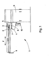
- FIG. 1 is a partial side view of the robot manipulator.
- the manipulator robot 1 allows the simultaneous loading and unloading of workpieces especially for machine tools such as lathes.
- the manipulator robot 1 comprises a mobile carriage 2.
- the mobile carriage 2 is mounted on a gantry 3.
- the mobile carriage 2 is movable in translation under the action of a jack. It allows a workpiece 4 to be brought from a first plate 5 to the working tool not shown in this figure and connected to a fastening device 6.
- This tool can be a cutter for example.
- the carriage makes it possible to deposit a machined part on a second plate not visible in this figure when it supports the raw part 4.
- the carriage 2 is provided with two claw-carrying heads 7.
- the carriage 2 is movable in horizontal translation but also in rotation about its guide axis. These two combined movements of translation and rotation of the carriage make it possible to simultaneously treat the blank and the workpiece.
- the plates serve as supports for the raw parts and the machined parts. These trays are arranged under the carriage 2 when it is in its position corresponding to the start of a work cycle as shown in this figure.
- the plates 5 are placed on supports 8 movable in vertical translation.
- the plates 5 are rotated at a determined angle at the end of each working cycle of the carriage 2 so as to be correctly positioned opposite the claw-bearing heads simultaneously treating the raw parts and the machined parts.
- the plates 5 are circular in shape and are provided at their periphery with pallet carriers allowing the accommodation of either the raw parts or the machined parts.
- the claw-bearing heads 7 are pivotally mounted on the carriage 2 which moves in translation along the arrow F.
- the various operations of a work cycle of the robot 1 are carried out from a programmable control unit 9.
- the work cycle of robot 1 is carried out as follows. First of all, the plates 5 are positioned in the axis of the carriage 2 of the gantry 3 and of the claw-carrying heads 7. The plates are moved vertically upwards using jacks 10. In this position, the claws of the first head are open to grip the blank 4. The claws of the head arranged on the other side of the carriage not shown in this figure are closed and enclose the machined part intended to be deposited on the corresponding plate.
- the claws of the head 7 enclose the blank to be machined. Simultaneously, the claws of the second head not shown in the figure are open and the workpiece is placed on the plate. This second head is therefore free to grasp a new machined part.
- the plates 5 are then lowered.
- the two heads 7 are rotated by 90 ° and the carriage 2 is launched in the direction of the machine tool.
- the gantry 3 is pivoted 90 °. After pivoting of the gantry, the carriage 2 traverses the introduction stroke by presenting the free head with its claws open. The claws are then closed to clamp the workpiece carried by the tool. The tool releases the workpiece and determines a slight backward movement of the carriage 2.
- the gantry carrying the carriage is pivoted by 180 ° so as to present the rough part facing the tool.
- the latter takes charge of the blank, which determines the opening of the claws of the released head and the recoil of the carriage 2.
- the gantry pivots 90 ° so that the free head can come opposite a new blank. to grasp when the carriage 2 has returned to its initial position. This determines the end of a work cycle.
- the loading device 11 comprises in particular a frame 12. The latter is provided on each of its sides with a vertical column 13.
- Each column 13 comprises an endless chain or any other similar device driven by a motor .
- Support arms 14 are attached to the endless chain. They carry circular plates 5.
- One of the columns 13 carries the plates provided with the raw parts while the other column carries the plates provided with the machined parts.
- a table 15 movable in horizontal translation under the effect of a jack 16 is disposed between the two columns 13.
- the arms 14 located opposite the table 15 of one of the columns 13 are moved downward while the arms 14 of the other column 13 are animated by an upward movement.
- This automatic loading device makes it possible to present the raw parts always at the same point with a single translational movement while simultaneously allowing to grasp a raw part and to remove the workpiece in one movement.
- the automatic loading device 11 is only shown partially.
- the two central plates 5 and the plate located at the extreme right of this drawing are arranged on the table 15 movable in translation under the effect of the jack 16.
- the plate 5, arranged at the extreme right of this figure comprises the machined parts intended to be transferred, while the plate 5, arranged on the far left of FIG. 5, comprises the raw parts intended to be supported by the table 15.
- the combined translation movements of the table 15 in translation horizontal and supports 8 in vertical translation allow in a single movement to obtain the release of the plate 5 carrying the machined parts and to present a new plate carrying the raw parts in the position suitable for their support by the claw-carrying head taking over the raw parts.
- the presentation of the raw parts is carried out on the plate along a single rotary axis determined by the support 8.
Landscapes
- Engineering & Computer Science (AREA)
- Mechanical Engineering (AREA)
- Feeding Of Workpieces (AREA)
- Manipulator (AREA)
- Specific Conveyance Elements (AREA)
Applications Claiming Priority (2)
| Application Number | Priority Date | Filing Date | Title |
|---|---|---|---|
| FR8502739A FR2577836A1 (fr) | 1985-02-26 | 1985-02-26 | Dispositif de chargement et de dechargement des pieces sur une machine comprenant un robot manipulateur |
| FR8502739 | 1985-02-26 |
Publications (2)
| Publication Number | Publication Date |
|---|---|
| EP0193463A2 true EP0193463A2 (de) | 1986-09-03 |
| EP0193463A3 EP0193463A3 (de) | 1988-03-23 |
Family
ID=9316619
Family Applications (1)
| Application Number | Title | Priority Date | Filing Date |
|---|---|---|---|
| EP86400384A Withdrawn EP0193463A3 (de) | 1985-02-26 | 1986-02-24 | Ein Handhabungsgerät aufweisende Vorrichtung zum Laden und Entladen von Werkstücken für eine Werkzeugmaschine |
Country Status (4)
| Country | Link |
|---|---|
| EP (1) | EP0193463A3 (de) |
| JP (1) | JPS61209848A (de) |
| ES (1) | ES8704782A1 (de) |
| FR (1) | FR2577836A1 (de) |
Cited By (1)
| Publication number | Priority date | Publication date | Assignee | Title |
|---|---|---|---|---|
| CN103112712A (zh) * | 2013-01-31 | 2013-05-22 | 深圳深蓝精机有限公司 | 装载设备 |
Family Cites Families (10)
| Publication number | Priority date | Publication date | Assignee | Title |
|---|---|---|---|---|
| DE1909498A1 (de) * | 1969-02-26 | 1970-09-10 | Dynamit Nobel Ag | Vorrichtung zum maschinellen Beschicken und Entleeren von Werkzeugmaschinen,vorzugsweise Pressen |
| JPS4716050U (de) * | 1971-03-24 | 1972-10-25 | ||
| IT948896B (it) * | 1972-01-20 | 1973-06-11 | Werkzeugmasch Okt Veb | Sistema di trasporto di disopsotivi portapezzi |
| GB1448863A (en) * | 1973-03-07 | 1976-09-08 | Clarke Chapman Ltd | Mechanical handling |
| IT990272B (it) * | 1973-08-17 | 1975-06-20 | Fmi Mecfond Aziende Mecc | Dispositivo automatico di trasferi mento di oggetti in lavorazione tra due macchine operatrici |
| IT1096423B (it) * | 1978-06-02 | 1985-08-26 | Curti Ezio | Dispositivo di caricamento e di scaricamento previsto tra due macchine disposte in successione |
| US4312618A (en) * | 1979-08-21 | 1982-01-26 | Acco Industries Inc. | Loader-unloader system for work pieces |
| EP0026790B1 (de) * | 1979-10-03 | 1983-12-28 | N.V. Mondiale 81 | Vorrichtung zum automatischen Werkstückwechseln an einer Drehbank |
| DE3140797C2 (de) * | 1981-10-14 | 1985-03-28 | Sakurai Ltd., Hamamatsu | Vorrichtung zum automatischen Zuführen und Entnehmen von Werkstücken für Rundlauf-Fräsmaschinen |
| FR2547221B1 (fr) * | 1983-06-09 | 1987-01-09 | Manurhin | Procede et dispositif de chargement-dechargement de pieces pour machine de tournage, et machine de tournage les mettant en oeuvre |
-
1985
- 1985-02-26 FR FR8502739A patent/FR2577836A1/fr active Pending
-
1986
- 1986-02-24 EP EP86400384A patent/EP0193463A3/de not_active Withdrawn
- 1986-02-26 JP JP4135486A patent/JPS61209848A/ja active Pending
- 1986-02-26 ES ES552435A patent/ES8704782A1/es not_active Expired
Cited By (2)
| Publication number | Priority date | Publication date | Assignee | Title |
|---|---|---|---|---|
| CN103112712A (zh) * | 2013-01-31 | 2013-05-22 | 深圳深蓝精机有限公司 | 装载设备 |
| CN103112712B (zh) * | 2013-01-31 | 2016-06-29 | 深圳深蓝精机有限公司 | 装载设备 |
Also Published As
| Publication number | Publication date |
|---|---|
| ES552435A0 (es) | 1987-04-16 |
| FR2577836A1 (fr) | 1986-08-29 |
| ES8704782A1 (es) | 1987-04-16 |
| JPS61209848A (ja) | 1986-09-18 |
| EP0193463A3 (de) | 1988-03-23 |
Similar Documents
| Publication | Publication Date | Title |
|---|---|---|
| EP2033725B1 (de) | Vorrichtung zum universellen automatischen Zuführen und Entladen von Werkstücken für Werkzeugmaschine | |
| EP0368977B1 (de) | Werkzeugmaschine für mehrere bearbeitungsarten und zur komplexen bearbeitung von langen werkstücken | |
| CN110449955B (zh) | 一种带料盘的全自动立式加工中心 | |
| CH648232A5 (fr) | Machine-outil. | |
| EP0185286B1 (de) | Verfahren zum automatischen Beschicken von Bearbeitungsstationen und Vorrichtung zur Durchführung des Verfahrens | |
| CH646892A5 (fr) | Procede de decoupage par decharges electriques. | |
| CH636543A5 (fr) | Machine-outil comprenant deux broches coaxiales opposees. | |
| FR2478497A1 (fr) | Presse a poinconner a tourelles porte-outils | |
| FR2626798A1 (fr) | Machine-outil a commande numerique a deux ensembles de broche porte-piece | |
| KR101306178B1 (ko) | 자동공급장치가 구비된 수차식 가공기 | |
| EP0193463A2 (de) | Ein Handhabungsgerät aufweisende Vorrichtung zum Laden und Entladen von Werkstücken für eine Werkzeugmaschine | |
| EP3520957A1 (de) | Fördervorrichtung für auf paletten gelagerten teilen, die in der nähe eines verabeitungszentrums positionierbar ist | |
| EP0283403A1 (de) | Handhabungsgerät zum Bestücken einer Werkzeugmaschine | |
| EP0032642B2 (de) | Drehbank mit horizontaler Spindel | |
| FR2651163A1 (fr) | Dispositif pour recevoir et transferer des pieces a la sortie d'une tronconneuse. | |
| CN213785251U (zh) | 一种多工位椰子去皮设备 | |
| EP0017601A1 (de) | Zufuhr- und Transportvorrichtung für spitzenlose Schleifmaschine und diese Vorrichtung enthaltende Maschinen | |
| FR2546432A1 (fr) | Procede et appareil pour le chargement et le dechargement de pieces sur une machine-outil | |
| EP0407537B1 (de) | Maschine und verfahren zum bearbeiten und/oder fertigbearbeiten von gegossenen oder bearbeiteten werkstücken | |
| CN112220065A (zh) | 一种多工位椰子去皮设备 | |
| JPH07156012A (ja) | ワーク切断システム | |
| EP0073687A1 (de) | Automatische Werkzeugwechselvorrichtung für eine Werkzeugmaschine | |
| EP0228974A1 (de) | Vorrichtung zur Trennung der Masselköpfe der Gussstücke | |
| JPH0542402A (ja) | バー材加工旋盤 | |
| FR2502687A1 (fr) | Dispositif pour la pose, a l'avancement, de panneaux de soutenement dans une galerie, procede pour la mise en oeuvre du dispositif et application |
Legal Events
| Date | Code | Title | Description |
|---|---|---|---|
| PUAI | Public reference made under article 153(3) epc to a published international application that has entered the european phase |
Free format text: ORIGINAL CODE: 0009012 |
|
| AK | Designated contracting states |
Kind code of ref document: A2 Designated state(s): AT BE CH DE GB IT LI LU NL SE |
|
| PUAL | Search report despatched |
Free format text: ORIGINAL CODE: 0009013 |
|
| AK | Designated contracting states |
Kind code of ref document: A3 Designated state(s): AT BE CH DE GB IT LI LU NL SE |
|
| STAA | Information on the status of an ep patent application or granted ep patent |
Free format text: STATUS: THE APPLICATION IS DEEMED TO BE WITHDRAWN |
|
| 18D | Application deemed to be withdrawn |
Effective date: 19880924 |
|
| RIN1 | Information on inventor provided before grant (corrected) |
Inventor name: PRIORE, NICOLAS |