EP0193509B1 - Mehrblattkollimator - Google Patents
Mehrblattkollimator Download PDFInfo
- Publication number
- EP0193509B1 EP0193509B1 EP86850068A EP86850068A EP0193509B1 EP 0193509 B1 EP0193509 B1 EP 0193509B1 EP 86850068 A EP86850068 A EP 86850068A EP 86850068 A EP86850068 A EP 86850068A EP 0193509 B1 EP0193509 B1 EP 0193509B1
- Authority
- EP
- European Patent Office
- Prior art keywords
- leaf
- collimator
- radiation
- leaves
- accordance
- Prior art date
- Legal status (The legal status is an assumption and is not a legal conclusion. Google has not performed a legal analysis and makes no representation as to the accuracy of the status listed.)
- Expired - Lifetime
Links
Images

Classifications
-
- G—PHYSICS
- G21—NUCLEAR PHYSICS; NUCLEAR ENGINEERING
- G21K—HANDLING OF PARTICLES OR IONISING RADIATION NOT OTHERWISE PROVIDED FOR; IRRADIATION DEVICES; GAMMA RAY OR X-RAY MICROSCOPES
- G21K1/00—Arrangements for handling particles or ionising radiation, e.g. focusing or moderating
- G21K1/02—Arrangements for handling particles or ionising radiation, e.g. focusing or moderating using diaphragms, collimators
- G21K1/04—Arrangements for handling particles or ionising radiation, e.g. focusing or moderating using diaphragms, collimators using variable diaphragms, shutters, choppers
- G21K1/046—Arrangements for handling particles or ionising radiation, e.g. focusing or moderating using diaphragms, collimators using variable diaphragms, shutters, choppers varying the contour of the field, e.g. multileaf collimators
-
- A—HUMAN NECESSITIES
- A61—MEDICAL OR VETERINARY SCIENCE; HYGIENE
- A61N—ELECTROTHERAPY; MAGNETOTHERAPY; RADIATION THERAPY; ULTRASOUND THERAPY
- A61N5/00—Radiation therapy
- A61N5/10—X-ray therapy; Gamma-ray therapy; Particle-irradiation therapy
- A61N5/1042—X-ray therapy; Gamma-ray therapy; Particle-irradiation therapy with spatial modulation of the radiation beam within the treatment head
- A61N5/1045—X-ray therapy; Gamma-ray therapy; Particle-irradiation therapy with spatial modulation of the radiation beam within the treatment head using a multi-leaf collimator, e.g. for intensity modulated radiation therapy or IMRT
-
- G—PHYSICS
- G21—NUCLEAR PHYSICS; NUCLEAR ENGINEERING
- G21K—HANDLING OF PARTICLES OR IONISING RADIATION NOT OTHERWISE PROVIDED FOR; IRRADIATION DEVICES; GAMMA RAY OR X-RAY MICROSCOPES
- G21K1/00—Arrangements for handling particles or ionising radiation, e.g. focusing or moderating
- G21K1/02—Arrangements for handling particles or ionising radiation, e.g. focusing or moderating using diaphragms, collimators
-
- A—HUMAN NECESSITIES
- A61—MEDICAL OR VETERINARY SCIENCE; HYGIENE
- A61N—ELECTROTHERAPY; MAGNETOTHERAPY; RADIATION THERAPY; ULTRASOUND THERAPY
- A61N5/00—Radiation therapy
- A61N5/10—X-ray therapy; Gamma-ray therapy; Particle-irradiation therapy
- A61N5/1048—Monitoring, verifying, controlling systems and methods
Definitions
- This invention pertains to a multi leaf collimator for a beam of radiation the particles of which are selected from the group comprising high energy photons, electrons, protons and heavy ions to the extent not already covered by said US Patent 4 463 266.
- Modern radiation therapy equipment use high energy particles to irradiate deep seated tumours. With high energy photons and electrons energies in the order of 1 to 50 MeV are considered for radiation therapy.
- wedge-shaped slabs are arranged in opposed pairs such that the inner opposed edges of each pair of slabs are always directed towards the effective radiation source. This will prevent the formation of an undesired penumbra, that is a half shaded area extending in the longitudinal direction of motion behind each slab. Due to the wedge like shape of each slab also the plane main side surfaces of each slab will be directed towards the radiation source thereby also preventing the formation of an undesired penumbra in the direction perpendicular to the said longitudinal direction.
- the slabs of said neutron collimator are much to thick to absorb the particles and will generate undesirable scatter. Since the slabs are of solid tungsten and low carbon soft iron the known neutron collimator is heavy and requires a sturdy frame for supporting the slabs. This is a drawback from constructional point of view.
- the air molecules within the collimator will interact with the particles of the radiation beam thereby giving rise to an effect appearing as if the effective radiation source is no longer, as desired, a point but rather an area of a certain extension. This is undesired since the particles emitted from the periphery of said area will cause an undesired scatter on the inner opposed edges and an increased penumbra resulting from the fact that neither the said inner edges nor the plane main side surfaces of the slab will point to the effective radiation source.
- the present invention concerns a multi leaf collimator avoiding the drawbacks of the neutron collimator in accordance with the prior art in order to produce high quality variable field shapes and to maintain a point type radiation source particularly when high energy electrons and photons are used for radiation therapy. Moreover, the weight of the collimator should be reduced.
- a multi leaf collimator for a beam of radiation the particles of which are selected from the group comprising high energy photons, electrons, protons and heavy ions which are emitted from a point type effective radiation source, comprising a protective radiation casing, a frame surrounded by the casing, a plurality of pairs of opposed, elongated, curved in cross section wedge-shaped leaves, wherein adjacent leaves are placed side by side such that a fan-shaped configuration converging towards an apex at the effective radiation source is achieved, each wedge-shaped leaf being mounted for a combined rotational and translational movement on a support structure such that the leaves of each pair are mounted for motion towards and away from each other along a path which intersects the edge of the radiation field from the radiation source at a right angle, the inner edge surface as well the two main surfaces of each leaf always being directed generally towards the radiation source, setting means for setting each leaf in a predetermined position along each individual path and read out means to determine the position of the leaves according to
- the protective casing is filled with helium gas at atmospheric pressure.
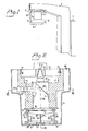
- FIG. 1 there is schematically shown an accelerator 1 for the production of a beam of high energy electrons which by a beam transportation system and a beam optical system within a rotary gantry 2 is directed into a rotary radiation head 3 mounted at the end of the gantry 2.
- the radiation head 3, comprises a frame 4, a multi leaf collimator 5 in accordance with the present invention and a protective casing 6 shown in broken lines.
- a conventional block collimator 7 is provided on the frame 4 to collimate the radiation beam in a direction perpendicular to the longitudinal direction of motion of the leaves of the collimator 5 in accordance with the present invention.
- the accelerated electron beam is projected onto a target 8.
- the target will act as a source of high energy photons, protons, electrons or heavy ions.
- a heavy metal primary collimator 9 Positioned downstream of the target 8 there is a heavy metal primary collimator 9 which is used to limit the maximum desired radiation beam.
- a flattening filter 10 and an ionization chamber 11 Positioned downstream of the primary collimator 9 and aligned with the opening of the collimator 9 there maybe a flattening filter 10 and an ionization chamber 11.
- the ionization chamber 11 is provided in the radiation field to measure dose rate and for other beam controlling purposes known per se and therefore not described here.
- the multi leaf collimator is mounted in a support structure generally designated 12.
- the support structure 12 is mounted at the bottom of the frame 4.
- the frame 4 and the elements mounted thereon are rotably supported by a bearing 13 on a circular top mounting plate 14.
- the support structure 12 comprises two opposed rectangular side walls 15 and 16 mounted at their respective upper end to a rectangular base plate 17 having a central opening 18 therein for the unhindered passage of the radiation.
- the side walls are at their lower end mounted to a lower plate 19 also provided with a rectangular opening 20 which is covered by a thin transparent film 21 forming the front surface of the radiation head 3.
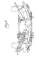
- a number of opposite pairs of elongated, curved and in cross section tapering leaves 30, 31 are slidably mounted between the upper and lower support bars 22-25. Since each leaf of each pair is supported in the same manner only leaf 31 and its support structure will be described in detail. It should therefore be understood that the corresponding constructional parts are provided for a leaf 30. Moreover, this construction is repeated for each further leaf 31 and each further leaf 30. In the preferred embodiment there are 32 pair of leaves 30, 31. Each leaf is made by solid lead, tungsten, uranium or by another material having a high density and atomic number or more generally high interaction cross section for the radiation at hand. The height of each leaf is about 70 mm and the length about 30 cm. As seen from Fig.
- each leaf is in cross section tapering and the width of the leaf is of he order of about 7 mm.
- Each leaf has a curved upper and a curved lower surface 32 and 33 respectively. The curvature is such that each surface would form a part of an imagined circle having its center close to the effective source of radiation which in Fig. 2 is marked with an X.
- In the upper surface 32 there is a longitudinal V-shaped slot 34 schematically shown in Fig. 2 and a corresponding V-shaped slot 35 is provided in the lower surface 33.
- An upper roller 36 is spring biased into engagement with the upper slot 34.
- Two lower rollers 37 and 38 are supporting the leaf 32 in its lower slot 35.
- Each roller 37, 38 is rotary supported by the lower support bar 25 while the upper roller 36 is supported by the upper support bar 23 by a lever 40 at one end pivoting around a pivot shaft 41 common to all pair of leaves and at the other end thereof rotably mounting roller 36.
- An L-shaped plate 42 is at one end thereof rotably attached to a lever 40 and is at its opposite end attached to a compression spring 43 mounted at support bar 23.
- the provision of the compression spring 43 pressing roller 36 into engagement with the upper slot of the leaf 32 will provide for a smooth running of the leaf along a curved, circular path between the extreme positions of each leaf.
- leaf 31 is shown in its extreme projected position while leaf 30 is shown in its extreme retracted position. On moving the leaf 31 between the three rollers the leaf will perform a translational as well as rotational motion.
- the inner edge surface 45 of leaf 31 is arranged so as to always be in alignment with the effective radiation source X, that is said edge surface 45 forms a part of a radius of an imagined circle having its center in X. It is thus apparent that the radiation beam emitted from the effective radiation source X will sweep parallel along the inner edge surface 45 leaving no undesired penumbra. Should the edge 45 form an angle to said imagined radius then an undesired penumbra would result. In order to avoid such undesired penumbra also in a direction perpendicular to the longitudinal direction, i.e. the direction of motion, of leaf 31, that is in a direction generally perpendicular to the plane of the Fig.
- Setting means in order to set the position of each leaf is provided in the form of a motor 50 and an upwardly directed extension 51 provided on each leaf 31.
- the extension may be in the form of a bar which at its lower end is secured by screws to leaf 31 and which at its upper end is provided with a number of through openings.
- a pivot pin 52 is provided in the middle opening, said pivot pin being provided with a through hole having an internal thread.
- Athreaded output shaft 53 of the motor 50 is screwed into the threaded through hole of the pivot pin and it is thus apparent that rotation of the output shaft will cause leaf 31 to move along said curved circular path.
- each step motor 50 is pivotably mounted in a through opening provided in a motor mounting bar 54 extending between the side walls 15, 16.
- Each motor is individually controllable by way of a switch 55 provided on a switch mounting bar 56 also extending between said side walls 15, 16.
- a gasket 57 surrounds the switches 55 on the switch mounting bar and forms a gas tight seal against the protective casing 6 which at the area of the switch mounting bar is provided with a through opening so that each motor can be manually controlled by operating the switch.
- the inner edge 45 is provided with a step.
- a complementary step is provided in the opposite inner edge 60 of leaf 30 so that when the leaves are brought into contact with each other such as is the case with the upper and lower leaves shown in Fig. 5 no radiation will penetrate the joint between the contacting edges.
- the main surface 46 is provided with a step, generally shown at 61, and a complementary step is provided in the opposite main side surface of the leaf 31 as is shown by the broken line 62.
- a bulb 65 isprovided at the outside of frame 4.
- the light from the bulb is transmitted through a semi-transparent mirror 71 and is reflected by a mirror 66 downstream the radiation head.
- the arrangement is such, that the light from the bulb will illuminate the irradiated surface (for example the body of a patient).
- the illuminated surface would then be the radiation field as set by the multi leaf collimator 5, for example the off center kidney-shaped radiation field shown in Fig. 5.
- the air within the protective casing 6 is replaced with helium gas which is introduced through a valve 80 and is held at atmospheric pressure within the casing.
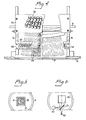
- said conductors are replaced by one single coaxial and control cable connected to a television camera 67 forming part of a read out and control system by which each individual leaf is set in a predetermined position along each individual path previously described.
- the read out system is shown in detail in Figs. 6 and 7 and comprises further to said TV-camera a mirror system including the semi-reflector mirror 66 and a semi-reflective mirror 71.
- the leaf collimator control system also includes a TV-camera control unit 72 a data processor 73 and a motor drive unit 74 including a separate drive units for each individual motor 50 and a TV-monitor 75.
- the TV-camera is so positioned as it, through the mirrors, appears to be at the centre of divergence X of the beam. It will thus, "look" into the radiation head and see the leaf collimator 5 from the effective radiation source. Ambient light reflected from the surface to be radiated is directed upstream the radiation head and will be seen by the television camera after reflection in mirrors 66 and 71. Replacing mirror 71 with an interference filter may further improve the contrast of the television picture. Suppose the interference filter is bluish, then the bluish portion of the light from the bulb 65 is filtered out and yellow like light will illuminate the blade collimator from above.
- Ambient light reflected from the radiated surface will, however, contain the bluish component just filtered out from the light which illuminates the collimator from above and accordingly the overall contrast is improved.
- the read out is performed with the field light from the bulb 65 on.
- the upper surface of the leaves is then provided with a reflective surface reflecting the field light back into the TV-camera.
- the TV-camera 67 is scanning the leaves along a direction which is parallel to the path along which each leave is movable. Each scanning line is accordingly scanning a pair of two opposing leaves as is illustrated in Fig. 8. In the preferred embodiment each leaf is scanned by eight lines 1-8 and the position of each leaf is determined by the light/dark transition appears in each scanning line.
- the TV-camera control unit 72 includes an converter for conversion of the analog picture information contained in each scanning line into data position signals which are processed by the processor 73. As is apparent from Fig. 8 each scanning line comprises information on the position of the right end of the left leaf 31 indicated by LE in the drawing and the position of the left end of the right leaf 30 indicated by RE.
- each light bar comprises a rod of polymethyl-methacrylate (PMMA) which at one end surface thereof is provided with a bulb directing its light into the rod.
- PMMA polymethyl-methacrylate
- light bar 76 is indicated by RR (right reference) and light bar 77 by LR (left reference).
- data relating to the positions of the contour line of the field to be radiated is stored in the processor and are compared with the data position signals relating to LE and LR.
- Fig. 8 LC represents a portion of the left contoure line of the field to be radiated while RC represents a portion along the right hand of said contoure line.
- the radiation field should be the area between LC and LC in Fig. 8.
- LE of leaf 31 should be moved to the left into alignment with LC in order to take the correct setting.
- LR of leaf 30 should be moved to the right into alignment with RC.
- the processor 73 data representing the current position of LE are continuously compared with data representing the position of LC and if there is any deviation therebetween the processor is programmed to output a control signal to the motor 50 so as to energize the latter until it has moved LE of 31 into alignment with LC. In a similar way the motor 50 driving leaf 50 is controlled by the processor.
- each required datum i.e LR, LE, RE and RR in separate scannings.
- a pair of opposing leaves is scanned in eight lines 1-8 as shown in Fig. 8.
- line 2 the datum representing the position of LR is taken, during scanning line 3 LE is taken, during line 4 RE is taken, during line 5 RR is taken. During the other 4 lines no data are taken.
- the position of the blades of the collimator can be viewed in the TV-monitor 75 also forming part of the read out system.
- the positions of LC and RC are stored in the processor 72 at a time prior to the actual setting of the leaves 30, 31.
- LC and RC position data may be entered manually into the processor or may be taken directly from the central processor of a computerized tomography system.
- the contoure line of the field to be irradiated is drawn directly on the patient's skin and data relating to the contoure line as drawn are taken for example during scanning line 2 for LC and during scanning line 4 for RC.
Landscapes
- Physics & Mathematics (AREA)
- Engineering & Computer Science (AREA)
- Health & Medical Sciences (AREA)
- Spectroscopy & Molecular Physics (AREA)
- General Engineering & Computer Science (AREA)
- High Energy & Nuclear Physics (AREA)
- Biomedical Technology (AREA)
- Nuclear Medicine, Radiotherapy & Molecular Imaging (AREA)
- Pathology (AREA)
- Radiology & Medical Imaging (AREA)
- Life Sciences & Earth Sciences (AREA)
- Animal Behavior & Ethology (AREA)
- General Health & Medical Sciences (AREA)
- Public Health (AREA)
- Veterinary Medicine (AREA)
- Radiation-Therapy Devices (AREA)
- Apparatus For Radiation Diagnosis (AREA)
Claims (10)
Applications Claiming Priority (2)
| Application Number | Priority Date | Filing Date | Title |
|---|---|---|---|
| US06/706,771 US4672212A (en) | 1985-02-28 | 1985-02-28 | Multi leaf collimator |
| US706771 | 1985-02-28 |
Publications (3)
| Publication Number | Publication Date |
|---|---|
| EP0193509A2 EP0193509A2 (de) | 1986-09-03 |
| EP0193509A3 EP0193509A3 (en) | 1987-01-21 |
| EP0193509B1 true EP0193509B1 (de) | 1990-09-05 |
Family
ID=24838980
Family Applications (1)
| Application Number | Title | Priority Date | Filing Date |
|---|---|---|---|
| EP86850068A Expired - Lifetime EP0193509B1 (de) | 1985-02-28 | 1986-02-24 | Mehrblattkollimator |
Country Status (4)
| Country | Link |
|---|---|
| US (1) | US4672212A (de) |
| EP (1) | EP0193509B1 (de) |
| JP (1) | JPH0631885B2 (de) |
| DE (1) | DE3673839D1 (de) |
Cited By (4)
| Publication number | Priority date | Publication date | Assignee | Title |
|---|---|---|---|---|
| DE19905823C1 (de) * | 1999-02-12 | 2000-06-08 | Deutsches Krebsforsch | Kollimator zum Begrenzen eines Bündels energiereicher Strahlen |
| US7489765B2 (en) | 2006-03-02 | 2009-02-10 | Ge Medical Systems Global Technology Company, Llc | Collimator control method and apparatus, and radiography system |
| DE102009006097B4 (de) * | 2008-02-29 | 2010-11-11 | Korea Institute Of Radiological & Medical Sciences | Kollimatorvorrichtung für Radiotherapiezwecke und ein die Vorrichtung verwendendes Radiotherapiegerät |
| DE102008004445B4 (de) * | 2007-06-01 | 2011-03-24 | Mitsubishi Electric Corp. | Teilchenstrahl-Behandlungssystem |
Families Citing this family (50)
| Publication number | Priority date | Publication date | Assignee | Title |
|---|---|---|---|---|
| US4868843A (en) * | 1986-09-10 | 1989-09-19 | Varian Associates, Inc. | Multileaf collimator and compensator for radiotherapy machines |
| GB2211710A (en) * | 1987-10-28 | 1989-07-05 | Philips Nv | Multileaf collimator |
| GB2211709B (en) * | 1987-10-28 | 1991-03-20 | Philips Electronic Associated | Multileaf collimator and related apparatus |
| DE3739006A1 (de) * | 1987-11-17 | 1989-05-24 | Siemens Ag | Konturenkollimator fuer die strahlentherapie |
| EP0371303B1 (de) * | 1988-11-29 | 1994-04-27 | Varian International AG. | Strahlentherapiegerät |
| DE3900884C2 (de) * | 1989-01-13 | 1994-03-03 | Schaefter & Kirchhoff | Vorrichtung zum Bestrahlen von operativ freigelegten Tumoren und/oder Tumorgebieten |
| DE3928282A1 (de) * | 1989-08-26 | 1991-02-28 | Philips Patentverwaltung | Roentgenaufnahmevorrichtung |
| JPH0416799A (ja) * | 1990-05-11 | 1992-01-21 | Mitsubishi Electric Corp | 粒子加速装置の照射ヘッド |
| US5166531A (en) * | 1991-08-05 | 1992-11-24 | Varian Associates, Inc. | Leaf-end configuration for multileaf collimator |
| DE4203610C1 (en) * | 1992-02-07 | 1993-08-05 | Siemens Ag, 8000 Muenchen, De | Contour collimator for radiation therapy - contains two opposing packets of lamellas between side walls with compressing springs and restoring device |
| US5563924A (en) * | 1994-02-04 | 1996-10-08 | Siemens Aktiengesellschaft | X-ray apparatus having an adjustable primary radiation diaphragm |
| DE69624562T2 (de) * | 1995-04-18 | 2003-07-03 | Loma Linda University Medical Center, Loma Linda | System für mehrfachpartikel-therapie |
| US5668371A (en) * | 1995-06-06 | 1997-09-16 | Wisconsin Alumni Research Foundation | Method and apparatus for proton therapy |
| DE19536804A1 (de) * | 1995-10-02 | 1997-04-03 | Deutsches Krebsforsch | Konturenkollimator für die Strahlentherapie |
| US5745545A (en) * | 1996-08-16 | 1998-04-28 | Siemens Medical Systems, Inc. | Alignment system and method for intra-operative radiation therapy |
| US6052430A (en) * | 1997-09-25 | 2000-04-18 | Siemens Medical Systems, Inc. | Dynamic sub-space intensity modulation |
| IL121866A (en) | 1997-09-29 | 2000-11-21 | Ein Gal Moshe | Multiple layer multileaf collimator |
| DE19936068A1 (de) * | 1999-07-30 | 2001-02-08 | Deutsches Krebsforsch | Medizinisches Bestrahlungsgerät und Verfahren zur Positionierung eines Körperteils im Strahlungsfeld eines medizinischen Bestrahlungsgeräts |
| DE19950794A1 (de) * | 1999-10-21 | 2001-06-13 | Siemens Ag | Röntgeneinrichtung und Verfahren zur Beeinflussung von Röntgenstrahlung |
| DE10045260C1 (de) * | 2000-09-13 | 2002-01-24 | Deutsches Krebsforsch | Potentiometer zur Wegerfassung |
| GB2367993B (en) * | 2000-10-11 | 2005-04-20 | Elekta Ab | Radiotherapy apparatus |
| CN1251646C (zh) | 2001-03-29 | 2006-04-19 | 株式会社东芝 | 诊断用x射线系统 |
| US6813337B2 (en) * | 2001-07-20 | 2004-11-02 | Siemens Medical Solutions Usa, Inc | Removable electron multileaf collimator |
| CN100452246C (zh) * | 2001-10-23 | 2009-01-14 | 深圳市一体智能技术有限公司 | 多叶式准直器的成形检测方法 |
| DE10211492B4 (de) * | 2002-03-15 | 2008-05-15 | Siemens Ag | Lamelle,Lamellenkollimator, Vorrichtung zur Strahlenbegrenzung und Bestrahlungsgerät |
| US6904310B2 (en) * | 2002-05-07 | 2005-06-07 | Scimed Life Systems, Inc. | Customized material for improved radiopacity |
| DE10323654A1 (de) * | 2003-05-26 | 2004-12-30 | GSI Gesellschaft für Schwerionenforschung mbH | Energiefiltereinrichtung |
| US6904125B2 (en) * | 2003-07-14 | 2005-06-07 | Cancer Care Ontario | Phantom for evaluating nondosimetric functions in a multi-leaf collimated radiation treatment planning system |
| WO2005018742A1 (en) * | 2003-08-11 | 2005-03-03 | Nomos Corporation | Method and aparatus for optimization of collimator angles in intensity modulated radiation therapy treatment |
| US7280633B2 (en) * | 2003-08-12 | 2007-10-09 | Loma Linda University Medical Center | Path planning and collision avoidance for movement of instruments in a radiation therapy environment |
| US7173265B2 (en) | 2003-08-12 | 2007-02-06 | Loma Linda University Medical Center | Modular patient support system |
| US7167542B2 (en) * | 2004-09-27 | 2007-01-23 | Siemens Medical Solutions Usa, Inc. | Motor arrangement and methods for a multi-leaf collimator |
| RU2281692C1 (ru) * | 2004-12-28 | 2006-08-20 | Александр Николаевич Черний | Устройство для диафрагмирования рабочего пучка медицинского рентгенодиагностического аппарата |
| JP4817859B2 (ja) * | 2005-03-04 | 2011-11-16 | 株式会社東芝 | 放射線絞り装置及び当該絞り装置を有する放射線治療装置 |
| JP4703421B2 (ja) * | 2006-02-02 | 2011-06-15 | 株式会社東芝 | マルチリーフコリメータ及びこれを備えた放射線治療装置 |
| EP2095374A4 (de) | 2006-11-21 | 2012-05-30 | Univ Loma Linda Med | Vorrichtung und verfahren zur fixierung von patienten zur bruststrahlungstherapie |
| US8093572B2 (en) * | 2007-06-29 | 2012-01-10 | Accuray Incorporated | Integrated variable-aperture collimator and fixed-aperture collimator |
| JP4717859B2 (ja) * | 2007-08-03 | 2011-07-06 | 住友重機械工業株式会社 | マルチリーフコリメータ及び放射線治療装置 |
| EP2285447B1 (de) * | 2008-04-21 | 2013-06-12 | Elekta AB (publ) | Verbesserungen von oder im zusammenhang mit multi-leaf-kollimatoren |
| US8938051B2 (en) | 2008-04-21 | 2015-01-20 | Elekta Ab (Publ) | Multi-leaf collimators |
| US8269198B2 (en) * | 2009-01-23 | 2012-09-18 | F. Avraham Dilmanian | Heavy ion therapy with microbeams |
| JP6125286B2 (ja) * | 2013-03-15 | 2017-05-10 | 住友重機械工業株式会社 | マルチリーフコリメータ及び荷電粒子線治療装置 |
| DE102013222209A1 (de) * | 2013-10-31 | 2015-04-30 | Fraunhofer-Gesellschaft zur Förderung der angewandten Forschung e.V. | Blendensystem für eine Strahlenquelle sowie Vorrichtung und Verfahren zum Aufnehmen eines Projektionsbilds und zum Bestimmen einer Relativposition zwischen einer Strahlenquelle und einem Strahlendetektor |
| GB2526103A (en) * | 2014-05-13 | 2015-11-18 | Elekta Ab | Collimation apparatus for radiotherapy |
| US9774838B2 (en) * | 2015-06-12 | 2017-09-26 | Accuray Incorporated | Ambient light suppression using color space information to derive pixel-wise attenuation factors |
| WO2017041750A1 (en) | 2015-09-10 | 2017-03-16 | Shanghai United Imaging Healthcare Co., Ltd. | Multi-leaf collimator and driving system |
| RU2019121943A (ru) | 2016-12-13 | 2021-01-15 | Вьюрэй Текнолоджиз, Инк. | Системы и способы лучевой терапии |
| CN110148483B (zh) * | 2019-05-31 | 2024-08-02 | 广东太微加速器有限公司 | 一种中子束调整装置 |
| CN110164582B (zh) * | 2019-05-31 | 2024-08-27 | 广东太微加速器有限公司 | 一种可对快中子束径调整的中子准直装置 |
| US12033768B2 (en) | 2021-05-20 | 2024-07-09 | Curium Us Llc | Target carrier assembly and irradiation system |
Family Cites Families (10)
| Publication number | Priority date | Publication date | Assignee | Title |
|---|---|---|---|---|
| DE192300C (de) * | ||||
| US2904692A (en) * | 1956-01-21 | 1959-09-15 | Siemens Reiniger Werke Ag | Device for collimation of a ray beam |
| DE1010659B (de) * | 1956-01-21 | 1957-06-19 | Siemens Reiniger Werke Ag | Vorrichtung zur Ausblendung eines Nutzstrahlenbuendels |
| DE2727505A1 (de) * | 1977-06-18 | 1979-01-04 | Ibm Deutschland | Roentgenfluoreszenzanalyse zur untersuchung oberflaechennaher schichten |
| DE3030332C2 (de) * | 1980-08-11 | 1983-04-07 | Siemens AG, 1000 Berlin und 8000 München | Primärstrahlenblende für ein Röntgenuntersuchungsgerät |
| JPS57139700A (en) * | 1981-02-20 | 1982-08-28 | Scanditronix Instr | Neutron collimater |
| US4463266A (en) * | 1981-02-20 | 1984-07-31 | Instrument Ab Scanditronix | Neutron collimator |
| FR2500677A1 (fr) * | 1981-02-24 | 1982-08-27 | Scanditronix Instr | Collimateur de neutrons |
| JPS5822072A (ja) * | 1981-07-31 | 1983-02-09 | 株式会社東芝 | 放射線照射野限定装置 |
| US4432370A (en) * | 1981-10-14 | 1984-02-21 | The Board Of Trustees Of The Leland Stanford Junior University | Method and means for minimally invasive angiography using mono-chromatized synchrotron radiation |
-
1985
- 1985-02-28 US US06/706,771 patent/US4672212A/en not_active Expired - Lifetime
-
1986
- 1986-02-24 EP EP86850068A patent/EP0193509B1/de not_active Expired - Lifetime
- 1986-02-24 DE DE8686850068T patent/DE3673839D1/de not_active Expired - Fee Related
- 1986-02-27 JP JP61042770A patent/JPH0631885B2/ja not_active Expired - Fee Related
Cited By (6)
| Publication number | Priority date | Publication date | Assignee | Title |
|---|---|---|---|---|
| DE19905823C1 (de) * | 1999-02-12 | 2000-06-08 | Deutsches Krebsforsch | Kollimator zum Begrenzen eines Bündels energiereicher Strahlen |
| US7489765B2 (en) | 2006-03-02 | 2009-02-10 | Ge Medical Systems Global Technology Company, Llc | Collimator control method and apparatus, and radiography system |
| DE102007008710B4 (de) * | 2006-03-02 | 2009-06-04 | GE Medical Systems Global Technology Company, LLC, Waukesha | Kollimatorsteuerungsverfahren und -vorrichtung und Radiographiesystem |
| DE102008004445B4 (de) * | 2007-06-01 | 2011-03-24 | Mitsubishi Electric Corp. | Teilchenstrahl-Behandlungssystem |
| DE102009006097B4 (de) * | 2008-02-29 | 2010-11-11 | Korea Institute Of Radiological & Medical Sciences | Kollimatorvorrichtung für Radiotherapiezwecke und ein die Vorrichtung verwendendes Radiotherapiegerät |
| DE102009006097B8 (de) * | 2008-02-29 | 2011-03-17 | Korea Institute Of Radiological & Medical Sciences | Kollimatorvorrichtung für Radiotherapiezwecke und ein die Vorrichtung verwendendes Radiotherapiegerät |
Also Published As
| Publication number | Publication date |
|---|---|
| EP0193509A3 (en) | 1987-01-21 |
| EP0193509A2 (de) | 1986-09-03 |
| DE3673839D1 (de) | 1990-10-11 |
| US4672212A (en) | 1987-06-09 |
| JPH0631885B2 (ja) | 1994-04-27 |
| JPS61269098A (ja) | 1986-11-28 |
Similar Documents
| Publication | Publication Date | Title |
|---|---|---|
| EP0193509B1 (de) | Mehrblattkollimator | |
| US5012506A (en) | Multileaf collimator | |
| JP3962844B2 (ja) | プリ・ペイシェント・コリメータ | |
| KR100943297B1 (ko) | 고 에너지광선을 한정하는 시준기 | |
| US4987309A (en) | Radiation therapy unit | |
| CA1096055A (en) | Variable collimator | |
| US5164976A (en) | Scanning mammography system with improved skin line viewing | |
| US4969174A (en) | Scanning mammography system with reduced scatter radiation | |
| US4998270A (en) | Mammographic apparatus with collimated controllable X-ray intensity and plurality filters | |
| US5166531A (en) | Leaf-end configuration for multileaf collimator | |
| US4868844A (en) | Mutileaf collimator for radiotherapy machines | |
| US5090037A (en) | Helical scanning computed tomography with tracking x-ray source | |
| EP0824026B1 (de) | Bestrahlungsbehandlungsvorrichtung und Verfahren | |
| EP0485998B1 (de) | Röntgeneinrichtung | |
| EP1364375B1 (de) | Radiotherapeutische Vorrichtung | |
| EP0105032A2 (de) | Verfahren und Apparat zur Bestrahlung von Objekten mit Röntgenstrahlen | |
| US20060023842A1 (en) | Single-leaf X-ray collimator | |
| US5224136A (en) | Helical scanning computed tomography apparatus with constrained tracking of the x-ray source | |
| NL8001707A (nl) | Inrichting voor het bepalen van lokale absorptie- verschillen in een objekt. | |
| KR101689082B1 (ko) | 키스톤 보정을 이용한 방사선 조사야 조절장치와 그 방법 | |
| US5442673A (en) | Fixed septum collimator for electron beam tomography | |
| CN1618402B (zh) | 用于减小辐射剂量的系统和方法 | |
| US3322950A (en) | Linear accelerator radiotherapy device and associated beam defining structure | |
| US5293416A (en) | Radiography apparatus for producing X-ray shadowgraphs | |
| EP0793981A2 (de) | Kollimator für die Strahlentherapie |
Legal Events
| Date | Code | Title | Description |
|---|---|---|---|
| PUAI | Public reference made under article 153(3) epc to a published international application that has entered the european phase |
Free format text: ORIGINAL CODE: 0009012 |
|
| AK | Designated contracting states |
Kind code of ref document: A2 Designated state(s): DE FR GB SE |
|
| PUAL | Search report despatched |
Free format text: ORIGINAL CODE: 0009013 |
|
| AK | Designated contracting states |
Kind code of ref document: A3 Designated state(s): DE FR GB SE |
|
| 17P | Request for examination filed |
Effective date: 19870202 |
|
| 17Q | First examination report despatched |
Effective date: 19880609 |
|
| GRAA | (expected) grant |
Free format text: ORIGINAL CODE: 0009210 |
|
| AK | Designated contracting states |
Kind code of ref document: B1 Designated state(s): DE FR GB SE |
|
| REF | Corresponds to: |
Ref document number: 3673839 Country of ref document: DE Date of ref document: 19901011 |
|
| ET | Fr: translation filed | ||
| PLBE | No opposition filed within time limit |
Free format text: ORIGINAL CODE: 0009261 |
|
| STAA | Information on the status of an ep patent application or granted ep patent |
Free format text: STATUS: NO OPPOSITION FILED WITHIN TIME LIMIT |
|
| 26N | No opposition filed | ||
| EAL | Se: european patent in force in sweden |
Ref document number: 86850068.7 |
|
| REG | Reference to a national code |
Ref country code: GB Ref legal event code: IF02 |
|
| PGFP | Annual fee paid to national office [announced via postgrant information from national office to epo] |
Ref country code: FR Payment date: 20030131 Year of fee payment: 18 |
|
| PGFP | Annual fee paid to national office [announced via postgrant information from national office to epo] |
Ref country code: GB Payment date: 20030210 Year of fee payment: 18 |
|
| PGFP | Annual fee paid to national office [announced via postgrant information from national office to epo] |
Ref country code: SE Payment date: 20030213 Year of fee payment: 18 |
|
| PGFP | Annual fee paid to national office [announced via postgrant information from national office to epo] |
Ref country code: DE Payment date: 20030225 Year of fee payment: 18 |
|
| PG25 | Lapsed in a contracting state [announced via postgrant information from national office to epo] |
Ref country code: GB Free format text: LAPSE BECAUSE OF NON-PAYMENT OF DUE FEES Effective date: 20040224 |
|
| PG25 | Lapsed in a contracting state [announced via postgrant information from national office to epo] |
Ref country code: SE Free format text: LAPSE BECAUSE OF NON-PAYMENT OF DUE FEES Effective date: 20040225 |
|
| PG25 | Lapsed in a contracting state [announced via postgrant information from national office to epo] |
Ref country code: DE Free format text: LAPSE BECAUSE OF NON-PAYMENT OF DUE FEES Effective date: 20040901 |
|
| EUG | Se: european patent has lapsed | ||
| GBPC | Gb: european patent ceased through non-payment of renewal fee |
Effective date: 20040224 |
|
| PG25 | Lapsed in a contracting state [announced via postgrant information from national office to epo] |
Ref country code: FR Free format text: LAPSE BECAUSE OF NON-PAYMENT OF DUE FEES Effective date: 20041029 |
|
| REG | Reference to a national code |
Ref country code: FR Ref legal event code: ST |