EP0193521A2 - Vorrichtung zum Messen der Griffigkeit von Flächen, insbesondere von Verkehrsflächen, wie Strassendecken - Google Patents
Vorrichtung zum Messen der Griffigkeit von Flächen, insbesondere von Verkehrsflächen, wie Strassendecken Download PDFInfo
- Publication number
- EP0193521A2 EP0193521A2 EP86890039A EP86890039A EP0193521A2 EP 0193521 A2 EP0193521 A2 EP 0193521A2 EP 86890039 A EP86890039 A EP 86890039A EP 86890039 A EP86890039 A EP 86890039A EP 0193521 A2 EP0193521 A2 EP 0193521A2
- Authority
- EP
- European Patent Office
- Prior art keywords
- rotor
- measuring
- rotor shaft
- bearing
- supporting structure
- Prior art date
- Legal status (The legal status is an assumption and is not a legal conclusion. Google has not performed a legal analysis and makes no representation as to the accuracy of the status listed.)
- Granted
Links
Images
Classifications
-
- G—PHYSICS
- G01—MEASURING; TESTING
- G01N—INVESTIGATING OR ANALYSING MATERIALS BY DETERMINING THEIR CHEMICAL OR PHYSICAL PROPERTIES
- G01N19/00—Investigating materials by mechanical methods
- G01N19/02—Measuring coefficient of friction between materials
Definitions
- the invention relates to a device for measuring the grip of surfaces, in particular traffic areas, such as road surfaces, etc., but also floor coverings in buildings, garages, etc.
- the object of the invention is the development of such a device which can be produced at comparatively low cost and can be used as required and which is distinguished by a robust and simple design which is correspondingly easy to handle, so that it is easy to handle thanks to its low weight and small space requirement. can be transported from one location to another.
- the device consists of a support structure, which can be supported on the surface whose grip is to be checked, for the shaft of a rotor rotating about an axis perpendicular to the surface and equipped with at least one contact element and a measuring device for measuring the latter contact element which can be applied to the surface with friction in each case the rotation taken up by the rotor moment exists.
- the frictional resistance of the two, three or more centrally symmetrically arranged contact members distributed over the periphery of the rotor is converted into a measurable by the device, transmitted from the rotor shaft torque, resulting in an appreciable advantage that the varying loads of fictitious vehicle wheels or the like. can be simulated very simply by regulating the pressure exerted on the rotor.
- any atmospheric or physical conditions prevailing in practice, in particular weather conditions, can also be simulated very easily in the area enclosed by the structure, so that an optimal truthfulness of the measurement results can be achieved for very different conditions.
- the rotor is arranged at the lower end of a rotor shaft that is vertically movable in the supporting structure and can be placed against the surface with adjustable pressure.
- a feed line for a liquid such as water or an oil-water emulsion, floor care agent or the like, can be connected to a space, which can be sealed, in the area of the rotor, which is enclosed by the supporting structure of the rotor shaft.
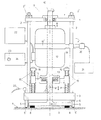
- the single drawing figure shows a side view of an embodiment of a device according to the invention.
- This device comprises a supporting structure 1, consisting of two (or more) uprights 2, the lower ends of which are screwed into a base 3 and the upper ends of which are fastened and held together on a spar 4 (or a cover plate) with screw nuts 2 '.
- the base 3 rests on a base ring 5, which has a seal 5 'on its underside and encloses a space 6 sealed in this way, in which the surface 7, e.g. on the surface of a traffic area, attachable rotor 9 equipped with contact elements 8 works.
- the contact members 8 can be rubber or plastic bodies which are Test in the direction of rotation of the rotor 9 have inclined and / or rounded contact surface and thus come into contact with surface 7 in a manner similar to a vehicle tire.
- the rotor 9 is arranged at the lower end of a rotor shaft 10 which passes through the supporting structure 1 over its full height and is mounted such that it can move in height in the region 11 of the upper end in the bearing 11 of the spar 4.
- This rotor shaft 10 in turn supports an electric drive motor 12 coaxially.
- the rotor shaft 10 is held in a holder 14 by a fixed bearing 13, which is immovable on the shaft 10, which is influenced by axially parallel coil springs 15.
- the pressure exerted by these helical springs 15 on the holder 14 and thus via the rotor shaft 10 on the rotor 9 against the surface 7 is by means of screw nuts 16 which embody the abutment for the helical springs 15 and are screwed onto the spring bolts 17 fastened in the base 3 , freely adjustable.
- An adjustment device which can be actuated by means of a lever 18 makes it possible to move the rotor 9 from a working position (shown in the drawing), in which it rests on the surface 7 with adjustable pressure, to a rest position, in which it is at a distance from this surface 7. to raise.
- the motor 12 which has to exert the torque required to rotate the rotor 9 on the rotor shaft 10, is in turn held against rotation by an arm 19 projecting radially from the housing on one of the uprights, between which, on the motor housing by means of a clamp 19 ' attached arm 19 and the post 2 a torque meter, for example a load cell 20 can be arranged to measure the torque exerted by the rotor 9 on the surface 7 and thus the frictional resistance (grip) of this surface 7.
- a torque measuring device can also be used within the scope of the invention, for example a torque measuring device directly associated with the rotor shaft 10.
- the measurement results supplied can be stored in a registration device, e.g. a chart recorder 21 are held.
- the motor 12 receives power from a conventional stationary or trans portable power source 22 and for regulating the motor speed, a speed controller 24, optionally working with a thyristor 23, is provided.
- the space 6 enclosed by the supporting structure 1 of the rotor shaft 10 in the region of the rotor 9 and optionally sealed with the seal 5 ' is provided with a feed line 25 for an arbitrarily selectable liquid, e.g. Water, oil emulsion, cleaning agents, etc., connectable.
- an arbitrarily selectable liquid e.g. Water, oil emulsion, cleaning agents, etc.
Landscapes
- Engineering & Computer Science (AREA)
- Automation & Control Theory (AREA)
- Physics & Mathematics (AREA)
- Health & Medical Sciences (AREA)
- Life Sciences & Earth Sciences (AREA)
- Chemical & Material Sciences (AREA)
- Analytical Chemistry (AREA)
- Biochemistry (AREA)
- General Health & Medical Sciences (AREA)
- General Physics & Mathematics (AREA)
- Immunology (AREA)
- Pathology (AREA)
- Force Measurement Appropriate To Specific Purposes (AREA)
Abstract
Description
- Die Erfindung betrifft eine Vorrichtung zum Messen der Griffigkeit von Flächen, insbesondere von Verkehrsflächen, wie Straßendecken, u.dgl., aber auch Bodenbelägen in Gebäuden, Garagen usw.
- Aufgabe der Erfindung ist die Entwicklung einer solchen Vorrichtung, die mit vergleichsweise geringem Kostenaufwand herstellbar und bedarfsweise einsetzbar ist und die sich durch eine robuste und einfache, sowie dementsprechend einfach handhabbare Gestaltung auszeichnet, so daß sie dank ihres geringen Gewichtes und geringen Raumbedarfes ohne Schwierig- ' keit von einem Einsatzort zum anderen befördert werden kann.
- Erfindungsgemäß wird diese Aufgabe dadurch gelöst, daß die Vorrichtung aus einem auf der Fläche, deren Griffigkeit geprüft werden soll, abstützbaren Tragwerk für die Welle eines um eine zur Fläche senkrechte Achse rotierenden, mit zumindest einem Kontaktorgan bestückten Rotor und einer Meßeinrichtung zum Messen der über dieses an die Fläche mit Reibung anlegbare Kontaktorgan jeweils vom Rotor aufgenommenen Drehmomentes besteht.
- Der Reibungswiderstand der zwei, drei oder mehr zentralsymmetrisch über die Peripherie des Rotors verteilt angeordneten Kontaktorgane wird in ein von der Vorrichtung meßbares, von der Rotorwelle übertragenes Drehmoment umgesetzt, wobei sich als schätzenswerter Vorteil ergibt, daß die variierenden Belastungen fiktiver Fahrzeugräder od.dgl. sehr einfach durch Regelung des auf den Rotor ausgeübten Druckes simuliert werden können.
- Weiters ergibt sich der gleichfalls wertvolle Vorteil, daß jederlei in der Praxis herrschende atmosphärische bzw. physikalische Zustände, insbesondere Witterungsverhältnisse, in dem vom Tragwerk umschlossenen Bereich gleichfalls sehr einfach simulierbar sind, so daß ein optimaler Wahrheitsgehalt der Meßergebnisse für ganz verschiedene Voraussetzungen zustandegebracht werden kann.
- Hiezu ist der Rotor nach einer bevorzugten Ausführungsform des Erfindungsgegenstandes am unteren Ende einer im Tragwerk höhenbeweglich lagernden Rotorwelle angeordnet und mit regelbarem Druck gegen die Fläche anlegbar.
- Ferner ist einem vom Tragwerk der Rotorwelle im Bereich des Rotors umschlossenen, gegebenenfalls abdichtbaren Raum eine Zufuhrleitung für eine Flüssigkeit, wie Wasser oder eine Öl-Wasser-Emulsion, Bodenpflegemittel od.dgl., anschließbar.
- Die einzige Zeichnungsfigur zeigt in einer Seitenansicht ein Ausführungsbeispiel einer erfindungsgemäßen Vorrichtung.
- Diese Vorrichtung umfaßt ein Tragwerk 1, bestehend aus zwei (oder mehr) Stehern 2, deren untere Enden in einer Basis 3 verschraubt sind und deren obere Enden an einem Holm 4 (oder einer Deckplatte) mit Schraubmuttern 2' befestigt und zusammengehalten sind. Die Basis 3 ruht auf einem Basisring 5, der an seiner Unterseite eine Dichtung 5' trägt und einen solcherart abgedichteten Raum 6 umschließt, in dem der auf einer Fläche 7, z.B. auf dem Belag einer Verkehrsfläche, aufsetzbare, mit Kontaktorganen 8 bestückte Rotor 9 arbeitet.
- Bei den Kontaktorganen 8 kann es sich um Gummi- oder Kunststoffkörper handeln, die in der Drehrichtung des Rotors 9 vorne eine abgeschrägte und/oder ausgerundete Anlauffläche aufweisen und somit ähnlich wie ein Fahrzeugreifen mit der Fläche 7 in Kontakt treten.
- Der Rotor 9 ist am unteren Ende einer Rotorwelle 10 angeordnet, die das Tragwerk 1 über dessen volle Höhe durchsetzt und im Bereich des oberen Endes im Lager 11 des Holmes 4 höhenbeweglich lagert.
- Diese Rotorwelle 10 lagert ihrerseits koaxial einen elektrischen Antriebsmotor 12. Mittels eines festen, also an der Welle 10 unverschiebbaren Lagers 13 wird die Rotorwelle 10 in einer Halterung 14 gehalten, die von achsparallelen Schraubenfedern 15 beeinflußt ist. Der von diesen Schraubenfedern 15 auf die Halterung 14 und damit über die Rotorwelle 10 auf den Rotor 9 ausgeübte Druck gegen die Fläche 7 ist mittels Schraubenmuttern 16, die das Widerlager für die Schraubenfedern 15 verkörpern und auf den in der Basis 3 befestigten Federbolzen 17 verschraubt sind, beliebig regelbar.
- Eine mittels eines Hebels 18 betätigbare Verstellvorrichtung ermöglicht es, den Rotor 9 aus einer - in der Zeichnung dargestellten - Arbeitsstellung, in der er auf der Fläche 7 mit regelbarem Druck aufliegt, in eine Ruhestellung, in der er von dieser Fläche 7 einen Abstand aufweist, anzuheben.
- Der Motor 12, der auf die Rotorwelle 10 das zur Drehung des Rotors 9 erforderliche Drehmoment auszuüben hat, wird hiezu seinerseits durch einen vom Gehäuse radial aüsragenden Arm 19 an einem der Steher gegen Drehung festgehalten, wobei zwischen diesem, am Motorgehäuse mittels einer Schelle 19' befestigten Arm 19 und dem Steher 2 ein Drehmoment-Messer, z.B. eine Meßdose, 20 angeordnet werden kann, um das jeweils vom Rotor 9 auf die Fläche 7 ausgeübte'Drehmoment und damit den Reibungswiderstand (die Griffigkeit) dieser Fläche 7 zu messen. Anstelle eines solchen Drehmomentmessers 20 kann aber im Rahmen der Erfindung auch jedwede andere Drehmoment-Meßvorrichtung eingesetzt werden, beispielsweise eine der Rotorwelle 10 unmittelbar zugeordnete Drehmoment-Meßvorrichtung.
- Die von der Meßdose 20 od.dgl. gelieferten Meßergebnisse können gewünschtenfalls in einer Registriervorrichtung, z.B. einem Meßschreiber 21, festgehalten werden.
- Der Motor 12 erhält Strom aus einer üblichen stationären oder transportablen Stromquelle 22 und zur Regelung der Motor-Drehzahl ist ein, gegebenenfalls mit einem Thyristor 23 arbeitender, Drehzahlregler 24 vorgesehen.
- Um die Griffigkeit der Fläche 7 unter Sonderbedingungen prüfen und messen zu können, ist dem vom Tragwerk 1 der Rotorwelle 10 im Bereich des Rotors 9 umschlossenen, gegebenenfalls mit der Dichtung 5' abgedichteten Raum 6 eine Zufuhrleitung 25 für eine beliebig wählbare Flüssigkeit, z.B. Wasser, Ölemulsion, Reinigungsmittel u.dgl., anschließbar.
- Selbstverständlich ist die Erfindung in ihren Einzelheiten mannigfaltig abwandelbar und durchaus nicht an die im Ausführungsbeispiel dargestellten und erläuterten Merkmale gebunden.
Claims (6)
gekennzeichnet durch
ein auf der Fläche (7) abstützbares Tragwerk (1) für die Welle (10) eines um eine zur Fläche (7) senkrechte Achse rotierenden, mit zumindest einem Kontaktorgan (8) bestückten Rotors (9) und eine Meßeinrichtung (20) zum Messen der über dieses an die Fläche (7) mit Reibung anlegbaren Kontaktorgan (8) jeweils vom Rotor (9) aufgenommenen Drehmomente.
Applications Claiming Priority (2)
| Application Number | Priority Date | Filing Date | Title |
|---|---|---|---|
| AT569/85 | 1985-02-26 | ||
| AT0056985A AT384109B (de) | 1985-02-26 | 1985-02-26 | Vorrichtung zum messen der griffigkeit von flaechen, insbesondere von verkehrsflaechen, wie strassendecken |
Publications (3)
| Publication Number | Publication Date |
|---|---|
| EP0193521A2 true EP0193521A2 (de) | 1986-09-03 |
| EP0193521A3 EP0193521A3 (en) | 1987-09-30 |
| EP0193521B1 EP0193521B1 (de) | 1991-07-10 |
Family
ID=3494080
Family Applications (1)
| Application Number | Title | Priority Date | Filing Date |
|---|---|---|---|
| EP86890039A Expired - Lifetime EP0193521B1 (de) | 1985-02-26 | 1986-02-20 | Vorrichtung zum Messen der Griffigkeit von Flächen, insbesondere von Verkehrsflächen, wie Strassendecken |
Country Status (4)
| Country | Link |
|---|---|
| US (1) | US4712418A (de) |
| EP (1) | EP0193521B1 (de) |
| AT (1) | AT384109B (de) |
| DE (1) | DE3680126D1 (de) |
Cited By (2)
| Publication number | Priority date | Publication date | Assignee | Title |
|---|---|---|---|---|
| WO2009049582A1 (de) * | 2007-10-19 | 2009-04-23 | Beab Brandenburg/H. Engineering & Anlagenbau Gmbh | Prüfgerät zur messung und prognose der griffigkeit von fahrbahndeckschichten und verfahren |
| EP2309248A3 (de) * | 2009-10-06 | 2011-07-06 | Centrum Dopravniho Vyzkumu | Mobile Vorrichtung zum Messen des Haftvermögens eines Straßenbelags |
Families Citing this family (15)
| Publication number | Priority date | Publication date | Assignee | Title |
|---|---|---|---|---|
| NL8701557A (nl) * | 1987-07-02 | 1989-02-01 | Skf Ind Trading & Dev | Werkwijze en inrichting voor het onderzoeken van slijtage- en wrijvingseigenschappen van loopvlakmaterialen bij glijdende wrijving. |
| CA2065524A1 (en) * | 1992-04-07 | 1993-10-08 | Paul Germain | Friction index tester |
| FR2751748B1 (fr) * | 1996-07-24 | 1998-09-25 | Labosport Soc | Procede de caracterisation d'une surface et dispositif pour la mise en oeuvre de ce procede |
| US5907090A (en) * | 1998-05-06 | 1999-05-25 | Gunderson; Dennis E. | Apparatus for measuring static and kinetic friction properties |
| US6679106B1 (en) * | 1998-10-23 | 2004-01-20 | Nippo Sangyo Co., Ltd. | Road surface roughness measuring device |
| USD468842S1 (en) | 2000-11-20 | 2003-01-14 | Donald R. May | Pier insert |
| DE10116760A1 (de) * | 2001-04-04 | 2002-10-17 | Bayer Ag | Vorrichtung und Verfahren zur Bestimmung eines Reibungskoeffizienten |
| US20040187556A1 (en) * | 2002-05-22 | 2004-09-30 | Hironari Abe | Method for measuring coefficient of friction |
| NL1021957C2 (nl) * | 2002-11-20 | 2004-05-24 | Ten Cate Thiolon Bv | Inrichting voor het meten van de statische en/of dynamische wrijvingscoefficient van een oppervlak. |
| AU2004270767B2 (en) * | 2003-09-11 | 2007-05-31 | The State Of Queensland Through Its Department Of Primary Industries & Fisheries | An apparatus and method for measuring surface properties |
| WO2005024396A1 (en) * | 2003-09-11 | 2005-03-17 | The State Of Queensland Through Its Department Of Primary Industries & Fisheries | An apparatus and method for measuring surface properties |
| US7000451B1 (en) | 2003-11-17 | 2006-02-21 | Wegand John C | Friction testing device |
| SE526858C2 (sv) * | 2004-03-05 | 2005-11-08 | Tomas Lackman | Anordning för utvärdering av skidvalla |
| CN106525307B (zh) * | 2016-08-04 | 2022-05-24 | 浙江工业大学 | 基于水下的仿生非光滑表面摩擦阻力测试装置 |
| FR3063808B1 (fr) * | 2017-03-08 | 2021-06-18 | Michelin & Cie | Procede de determination du coefficient de frottement statique pour une semelle de chaussure |
Family Cites Families (12)
| Publication number | Priority date | Publication date | Assignee | Title |
|---|---|---|---|---|
| US2441993A (en) * | 1945-12-05 | 1948-05-25 | Bendix Aviat Corp | Apparatus for testing friction material |
| GB1207692A (en) * | 1967-11-09 | 1970-10-07 | Ml Aviation Co Ltd | Measurement of the coefficient of friction between a vehicle wheel and a surface |
| DE1902773B2 (de) * | 1969-01-21 | 1971-10-07 | Vorrichtung zum messen der griffigkeit und verschleissfestig keit von strassenbaustoffen | |
| AT314874B (de) * | 1970-06-10 | 1974-04-25 | Jur Dipl Ing Fritz Gragger Dr | Vorrichtung zum Messen der Griffigkeit und Verschleißfestigkeit von Straßenbaustoffen |
| DE2148362C2 (de) * | 1971-09-28 | 1973-06-14 | Fina Deutsche Gmbh | Pruefgeraet fuer fahrbahndeckenmaterial |
| US3823599A (en) * | 1972-12-08 | 1974-07-16 | Steel Corp | Test apparatus for the evaluation of rolling lubricants |
| DE2326954A1 (de) * | 1973-05-26 | 1974-12-12 | Basf Farben & Fasern | Verfahren und vorrichtung zur bestimmung der qualitaet von strassenmarkierungen |
| US4050290A (en) * | 1974-11-27 | 1977-09-27 | Borje Arne Gunnar Lonnroth | Device for measuring friction between wheel and support |
| US4051713A (en) * | 1976-03-23 | 1977-10-04 | Actus, Inc. | Friction measuring and testing method and apparatus |
| DE2742110A1 (de) * | 1977-09-19 | 1979-03-29 | Willi Naumann | Pruefeinrichtung fuer den strassenzustand |
| DE2921677A1 (de) * | 1979-05-29 | 1980-12-11 | Sudbrack Bernfried | Vorrichtung und verfahren zum bestimmen der griffigkeit von kfz-reifen auf strassendecken |
| US4594878A (en) * | 1983-06-24 | 1986-06-17 | Nippo Sangyo Co. Ltd. | Dynamic friction coefficient measuring apparatus |
-
1985
- 1985-02-26 AT AT0056985A patent/AT384109B/de not_active IP Right Cessation
-
1986
- 1986-02-20 EP EP86890039A patent/EP0193521B1/de not_active Expired - Lifetime
- 1986-02-20 DE DE8686890039T patent/DE3680126D1/de not_active Expired - Lifetime
- 1986-02-26 US US06/833,207 patent/US4712418A/en not_active Expired - Fee Related
Cited By (3)
| Publication number | Priority date | Publication date | Assignee | Title |
|---|---|---|---|---|
| WO2009049582A1 (de) * | 2007-10-19 | 2009-04-23 | Beab Brandenburg/H. Engineering & Anlagenbau Gmbh | Prüfgerät zur messung und prognose der griffigkeit von fahrbahndeckschichten und verfahren |
| EA015762B1 (ru) * | 2007-10-19 | 2011-12-30 | Беаб Бранденбург/Х. Энжиниринг Унд Анлагенбау Гмбх | Прибор для измерения и прогнозирования шероховатости дорожных покрытий и способ его использования |
| EP2309248A3 (de) * | 2009-10-06 | 2011-07-06 | Centrum Dopravniho Vyzkumu | Mobile Vorrichtung zum Messen des Haftvermögens eines Straßenbelags |
Also Published As
| Publication number | Publication date |
|---|---|
| DE3680126D1 (de) | 1991-08-14 |
| AT384109B (de) | 1987-10-12 |
| US4712418A (en) | 1987-12-15 |
| EP0193521B1 (de) | 1991-07-10 |
| EP0193521A3 (en) | 1987-09-30 |
| ATA56985A (de) | 1987-02-15 |
Similar Documents
| Publication | Publication Date | Title |
|---|---|---|
| EP0193521A2 (de) | Vorrichtung zum Messen der Griffigkeit von Flächen, insbesondere von Verkehrsflächen, wie Strassendecken | |
| DE3423116A1 (de) | Vorrichtung zum messen des dynamischen reibungskoeffizienten | |
| DE3507906C2 (de) | ||
| DE102007001559B4 (de) | Stationäre Bohrmaschine | |
| DE2838399C3 (de) | Vorrichtung zur Vermessung des Lenkeinschlags und der Radlast von Rädern eines Fahrzeugs, vorzugsweise eines Kraftfahrzeugs | |
| EP0202525B1 (de) | Antrieb für Aufzüge und Verfahren zu dessen Montage | |
| DE2020257A1 (de) | Hoehenverstellbarer Untersatz fuer Maschinen,Instrumente od.dgl. | |
| DE69737587T2 (de) | Drehmomentmessvorrichtung für Flügelrad | |
| DE19817672C2 (de) | Prüfstand für Vergleichsmessungen der Beschleunigungsdauer von mehrrädrigen Fahrzeugen mit Motorantrieb | |
| DE1473480C3 (de) | ||
| DE2400921C3 (de) | Vorrichtung zum Prüfen mechanisch beanspruchter, radförmiger Teile | |
| DE102010037705B4 (de) | Hilfsantriebsvorrichtung, Rollstuhl und Verfahren zur Ermittlung der manuellen Antriebskraft eines Rollstuhlfahrers | |
| DE2923518C2 (de) | Einrichtung zum Abtragen von Boden vom Grund eines Sees | |
| DE1277585B (de) | Geraet zur direkten Bestimmung des Anzugsmomentes, der axialen Spannkraft und der Torsionsspannung, ferner zur indirekten Bestimmung der Reibungskoeffizienten an den beiden Enden eines Schraubenbolzens | |
| DE102004017679B4 (de) | Trainingsgerät | |
| DE2148362C2 (de) | Pruefgeraet fuer fahrbahndeckenmaterial | |
| DE2833354A1 (de) | Trimmgeraet fuer rollstuhlfahrer | |
| DE1157812B (de) | Vorrichtung zum Wuchten von Kraftfahrzeugraedern am Kraftfahrzeug | |
| DE412536C (de) | Kippsicherung fuer fahrbare, aufricht-, ausschieb- und drehbare Leitern | |
| DE10137567B4 (de) | Einrichtung zur Messung des Belegungsgewichtes eines verstellbaren Fahrzeugsitzes | |
| DE872833C (de) | Hebebuehne fuer Kraftfahrzeuge | |
| DE149384C (de) | ||
| AT220650B (de) | Fahrbare Fugenschneidmaschine | |
| AT318310B (de) | Maschinenauflager | |
| DE2406876C3 (de) | Hub- und Senkvorrichtung für Fahrzeuge |
Legal Events
| Date | Code | Title | Description |
|---|---|---|---|
| PUAI | Public reference made under article 153(3) epc to a published international application that has entered the european phase |
Free format text: ORIGINAL CODE: 0009012 |
|
| AK | Designated contracting states |
Kind code of ref document: A2 Designated state(s): BE CH DE FR GB IT LI LU NL SE |
|
| PUAL | Search report despatched |
Free format text: ORIGINAL CODE: 0009013 |
|
| AK | Designated contracting states |
Kind code of ref document: A3 Designated state(s): BE CH DE FR GB IT LI LU NL SE |
|
| 17P | Request for examination filed |
Effective date: 19880211 |
|
| 17Q | First examination report despatched |
Effective date: 19900323 |
|
| GRAA | (expected) grant |
Free format text: ORIGINAL CODE: 0009210 |
|
| AK | Designated contracting states |
Kind code of ref document: B1 Designated state(s): BE CH DE FR GB IT LI LU NL SE |
|
| PG25 | Lapsed in a contracting state [announced via postgrant information from national office to epo] |
Ref country code: IT Free format text: LAPSE BECAUSE OF FAILURE TO SUBMIT A TRANSLATION OF THE DESCRIPTION OR TO PAY THE FEE WITHIN THE PRESCRIBED TIME-LIMIT;WARNING: LAPSES OF ITALIAN PATENTS WITH EFFECTIVE DATE BEFORE 2007 MAY HAVE OCCURRED AT ANY TIME BEFORE 2007. THE CORRECT EFFECTIVE DATE MAY BE DIFFERENT FROM THE ONE RECORDED. Effective date: 19910710 Ref country code: BE Effective date: 19910710 Ref country code: NL Effective date: 19910710 Ref country code: SE Effective date: 19910710 Ref country code: GB Effective date: 19910710 |
|
| REF | Corresponds to: |
Ref document number: 3680126 Country of ref document: DE Date of ref document: 19910814 |
|
| EN | Fr: translation not filed | ||
| PG25 | Lapsed in a contracting state [announced via postgrant information from national office to epo] |
Ref country code: FR Effective date: 19911129 |
|
| NLV1 | Nl: lapsed or annulled due to failure to fulfill the requirements of art. 29p and 29m of the patents act | ||
| GBV | Gb: ep patent (uk) treated as always having been void in accordance with gb section 77(7)/1977 [no translation filed] | ||
| PG25 | Lapsed in a contracting state [announced via postgrant information from national office to epo] |
Ref country code: LU Free format text: LAPSE BECAUSE OF NON-PAYMENT OF DUE FEES Effective date: 19920229 |
|
| PLBE | No opposition filed within time limit |
Free format text: ORIGINAL CODE: 0009261 |
|
| STAA | Information on the status of an ep patent application or granted ep patent |
Free format text: STATUS: NO OPPOSITION FILED WITHIN TIME LIMIT |
|
| 26N | No opposition filed | ||
| REG | Reference to a national code |
Ref country code: FR Ref legal event code: ST |
|
| PGFP | Annual fee paid to national office [announced via postgrant information from national office to epo] |
Ref country code: DE Payment date: 19930421 Year of fee payment: 8 |
|
| PGFP | Annual fee paid to national office [announced via postgrant information from national office to epo] |
Ref country code: CH Payment date: 19930428 Year of fee payment: 8 |
|
| PG25 | Lapsed in a contracting state [announced via postgrant information from national office to epo] |
Ref country code: LI Effective date: 19940228 Ref country code: CH Effective date: 19940228 |
|
| REG | Reference to a national code |
Ref country code: CH Ref legal event code: PL |
|
| PG25 | Lapsed in a contracting state [announced via postgrant information from national office to epo] |
Ref country code: DE Effective date: 19941101 |