EP0193693B1 - Cisaille rotative - Google Patents
Cisaille rotative Download PDFInfo
- Publication number
- EP0193693B1 EP0193693B1 EP19850730035 EP85730035A EP0193693B1 EP 0193693 B1 EP0193693 B1 EP 0193693B1 EP 19850730035 EP19850730035 EP 19850730035 EP 85730035 A EP85730035 A EP 85730035A EP 0193693 B1 EP0193693 B1 EP 0193693B1
- Authority
- EP
- European Patent Office
- Prior art keywords
- drums
- knives
- axis
- point
- plane
- Prior art date
- Legal status (The legal status is an assumption and is not a legal conclusion. Google has not performed a legal analysis and makes no representation as to the accuracy of the status listed.)
- Expired - Lifetime
Links
Images

Classifications
-
- B—PERFORMING OPERATIONS; TRANSPORTING
- B23—MACHINE TOOLS; METAL-WORKING NOT OTHERWISE PROVIDED FOR
- B23D—PLANING; SLOTTING; SHEARING; BROACHING; SAWING; FILING; SCRAPING; LIKE OPERATIONS FOR WORKING METAL BY REMOVING MATERIAL, NOT OTHERWISE PROVIDED FOR
- B23D35/00—Tools for shearing machines or shearing devices; Holders or chucks for shearing tools
- B23D35/001—Tools for shearing machines or shearing devices; Holders or chucks for shearing tools cutting members
-
- B—PERFORMING OPERATIONS; TRANSPORTING
- B26—HAND CUTTING TOOLS; CUTTING; SEVERING
- B26D—CUTTING; DETAILS COMMON TO MACHINES FOR PERFORATING, PUNCHING, CUTTING-OUT, STAMPING-OUT OR SEVERING
- B26D1/00—Cutting through work characterised by the nature or movement of the cutting member or particular materials not otherwise provided for; Apparatus or machines therefor; Cutting members therefor
- B26D1/01—Cutting through work characterised by the nature or movement of the cutting member or particular materials not otherwise provided for; Apparatus or machines therefor; Cutting members therefor involving a cutting member which does not travel with the work
- B26D1/12—Cutting through work characterised by the nature or movement of the cutting member or particular materials not otherwise provided for; Apparatus or machines therefor; Cutting members therefor involving a cutting member which does not travel with the work having a cutting member moving about an axis
- B26D1/25—Cutting through work characterised by the nature or movement of the cutting member or particular materials not otherwise provided for; Apparatus or machines therefor; Cutting members therefor involving a cutting member which does not travel with the work having a cutting member moving about an axis with a non-circular cutting member
- B26D1/34—Cutting through work characterised by the nature or movement of the cutting member or particular materials not otherwise provided for; Apparatus or machines therefor; Cutting members therefor involving a cutting member which does not travel with the work having a cutting member moving about an axis with a non-circular cutting member moving about an axis parallel to the line of cut
- B26D1/40—Cutting through work characterised by the nature or movement of the cutting member or particular materials not otherwise provided for; Apparatus or machines therefor; Cutting members therefor involving a cutting member which does not travel with the work having a cutting member moving about an axis with a non-circular cutting member moving about an axis parallel to the line of cut and coacting with a rotary member
- B26D1/405—Cutting through work characterised by the nature or movement of the cutting member or particular materials not otherwise provided for; Apparatus or machines therefor; Cutting members therefor involving a cutting member which does not travel with the work having a cutting member moving about an axis with a non-circular cutting member moving about an axis parallel to the line of cut and coacting with a rotary member for thin material, e.g. for sheets, strips or the like
-
- B—PERFORMING OPERATIONS; TRANSPORTING
- B26—HAND CUTTING TOOLS; CUTTING; SEVERING
- B26D—CUTTING; DETAILS COMMON TO MACHINES FOR PERFORATING, PUNCHING, CUTTING-OUT, STAMPING-OUT OR SEVERING
- B26D1/00—Cutting through work characterised by the nature or movement of the cutting member or particular materials not otherwise provided for; Apparatus or machines therefor; Cutting members therefor
- B26D1/56—Cutting through work characterised by the nature or movement of the cutting member or particular materials not otherwise provided for; Apparatus or machines therefor; Cutting members therefor involving a cutting member which travels with the work otherwise than in the direction of the cut, i.e. flying cutter
- B26D1/62—Cutting through work characterised by the nature or movement of the cutting member or particular materials not otherwise provided for; Apparatus or machines therefor; Cutting members therefor involving a cutting member which travels with the work otherwise than in the direction of the cut, i.e. flying cutter and is rotating about an axis parallel to the line of cut, e.g. mounted on a rotary cylinder
- B26D1/626—Cutting through work characterised by the nature or movement of the cutting member or particular materials not otherwise provided for; Apparatus or machines therefor; Cutting members therefor involving a cutting member which travels with the work otherwise than in the direction of the cut, i.e. flying cutter and is rotating about an axis parallel to the line of cut, e.g. mounted on a rotary cylinder for thin material, e.g. for sheets, strips or the like
-
- B—PERFORMING OPERATIONS; TRANSPORTING
- B26—HAND CUTTING TOOLS; CUTTING; SEVERING
- B26D—CUTTING; DETAILS COMMON TO MACHINES FOR PERFORATING, PUNCHING, CUTTING-OUT, STAMPING-OUT OR SEVERING
- B26D1/00—Cutting through work characterised by the nature or movement of the cutting member or particular materials not otherwise provided for; Apparatus or machines therefor; Cutting members therefor
- B26D1/0006—Cutting members therefor
- B26D2001/0066—Cutting members therefor having shearing means, e.g. shearing blades, abutting blades
-
- Y—GENERAL TAGGING OF NEW TECHNOLOGICAL DEVELOPMENTS; GENERAL TAGGING OF CROSS-SECTIONAL TECHNOLOGIES SPANNING OVER SEVERAL SECTIONS OF THE IPC; TECHNICAL SUBJECTS COVERED BY FORMER USPC CROSS-REFERENCE ART COLLECTIONS [XRACs] AND DIGESTS
- Y10—TECHNICAL SUBJECTS COVERED BY FORMER USPC
- Y10T—TECHNICAL SUBJECTS COVERED BY FORMER US CLASSIFICATION
- Y10T83/00—Cutting
- Y10T83/465—Cutting motion of tool has component in direction of moving work
- Y10T83/4766—Orbital motion of cutting blade
- Y10T83/4795—Rotary tool
- Y10T83/4824—With means to cause progressive transverse cutting
-
- Y—GENERAL TAGGING OF NEW TECHNOLOGICAL DEVELOPMENTS; GENERAL TAGGING OF CROSS-SECTIONAL TECHNOLOGIES SPANNING OVER SEVERAL SECTIONS OF THE IPC; TECHNICAL SUBJECTS COVERED BY FORMER USPC CROSS-REFERENCE ART COLLECTIONS [XRACs] AND DIGESTS
- Y10—TECHNICAL SUBJECTS COVERED BY FORMER USPC
- Y10T—TECHNICAL SUBJECTS COVERED BY FORMER US CLASSIFICATION
- Y10T83/00—Cutting
- Y10T83/465—Cutting motion of tool has component in direction of moving work
- Y10T83/4766—Orbital motion of cutting blade
- Y10T83/4795—Rotary tool
- Y10T83/4824—With means to cause progressive transverse cutting
- Y10T83/4827—With helical cutter blade
-
- Y—GENERAL TAGGING OF NEW TECHNOLOGICAL DEVELOPMENTS; GENERAL TAGGING OF CROSS-SECTIONAL TECHNOLOGIES SPANNING OVER SEVERAL SECTIONS OF THE IPC; TECHNICAL SUBJECTS COVERED BY FORMER USPC CROSS-REFERENCE ART COLLECTIONS [XRACs] AND DIGESTS
- Y10—TECHNICAL SUBJECTS COVERED BY FORMER USPC
- Y10T—TECHNICAL SUBJECTS COVERED BY FORMER US CLASSIFICATION
- Y10T83/00—Cutting
- Y10T83/929—Tool or tool with support
- Y10T83/9372—Rotatable type
- Y10T83/9394—Helical tool
Definitions
- the present invention relates to a rotary drum shear including two drums rotating in the opposite direction to each other and each having a spiral knife on the periphery thereof so that material fed between the drums is cut by engagement of the knives brought by the rotation of the drums.
- a prior art rotary drum shear includes drums which are rotatably disposed at the upper and lower sides and carry straight knives fixedly mounted substantially parallelly along an axis of the drums, respectively.
- the drums are rotated in the opposite direction to each other so that the knives mounted on the drums are engaged with each other once per rotation to cut a long material fed between the drums by the engagement of the knives.
- a web cutoff device with a knife extending obliquely to the roll axis and its edge is inclined with respect to the roll surface is disclosed in US-A-2,478,240, however, the other knife of this device extends straight and axially of the roll.
- the trajectory of engaging point of the knives of this device is not perpendicular to the direction of the web feeding. Accordingly the cutoff line on the web is oblique.
- FIG. 1(a) is a perspective view showing a rotary drum shear including spiral knives and the cutting operation thereof.
- FIG. 1(b) shows a sectional view of the knives in the engagement condition taken along line I - I of FIG. 1(a).
- numerals 1 and 2 denote upper and lower drums, respectively, which is rotated at an equal speed and in the opposite direction to each other
- numerals 3 and 4 denote knives mounted spirally on the external peripheries of the drums 1 and 2, respectively
- numerals 5 denotes a long material to be cut which is fed between the drums 1 and 2.
- the material 5 is fed between the drums in a perpendicular direction to rotational axes of the drums 1 and 2.
- the cutting line for the material is inclined by an angle of 90°- ⁇ with regard to the feeding direction as shown in FIG. 1(a).
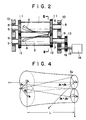
- numerals 1 and 2 denote upper and lower drums, respectively, each having shafts 6 and 7 of which ends are rotatably mounted on a frame 10 through bearings 8 and 9, respectively.
- Gears 11 and 12 which are fixedly mounted on the shafts 6 and 7 at both sides of the drums 1 and 2, respectively, are meshed with each other.
- a further gear 13 is fixedly mounted on the shaft 7 of the drum 7 at the outside of the frame 10.
- the gear 13 is meshed with a gear 16 mounted on a drive shaft 15 of a motor 14.
- the motor 14 rotates the upper and lower drums 1 and 2 in the opposite direction to each other and at the equal rotational speed (equal angular velocity).
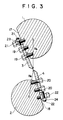
- Knives 3 and 4 are spirally mounted on the peripheries of the drums 1 and 2, respectively. More particularly, as shown in FIG. 3, fitting planes 17 and 18 are spirally formed on the upper and lower drums 1 and 2 and the knives 3 and 4 are fixedly mounted on the planes 17 and 18 by means of bolts 19 and 20. Adjusting bolts 21 and 22 and adjusting nuts 23 and 24 are provided on back sides of the knives 3 and 4 so that positions of the knives 3 and 4 can be adjusted finely.
- the upper and lower knives 3 and 4 are formed so that distances R A and R B each extending from the rotational center of the drum to the engagement position of the knives 3 and 4 are gradually reduced from a start position of the engagement along the axis of the knives 3 and 4.
- distances R A and R B each extending from the rotational center of the drum to the engagement position of the knives 3 and 4 are gradually reduced from a start position of the engagement along the axis of the knives 3 and 4.
- FIG. 4 it is considered that cutting edges of the knives are wound on a conical cylinder.
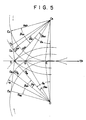
- FIG. 5 illustrates a projected state of FIG. 4 in the direction Z as an example of a shape of the knives.
- the upper knife 3 is shown by a line SE A connecting a start position S of the engagement to a termination position E A of the engagement and the lower knife 4 is shown by a line SE B in the same way.
- the knives 3 and 4 are engaged with each other at the start point S.
- the upper and lower drums 1 and 2 are rotated in the direction indicating arrows, respectively, and the material 5 to be cut moves in the direction of V P .
- the engagement point of the knives 3 and 4 is moved from the start point S through a point G on the line V P toward a point E in accordance with the movement of the material.
- the upper and lower knives 3 and 4 are formed so that a certain point G A on the cutting edge of the upper knife 3 which is away from line O A S by an angle ⁇ A is engaged at the point G with a certain point G B on the cutting edge of the lower knife 4 which is away from line O B S by an angle ⁇ B in FIG. 5.
- r A is a distance from the rotational center O A of the upper drum 1 to the engagement position of the knives
- r B is a distance from the rotational center O B of the lower drum 2 to the engagement position of the knives
- R SA is a distance between the start position S of the engagement of the knives and the center of the knife 1
- R SB is a distance between the start position S of the engagement of the knife and the center of the knife 2
- ⁇ A is an angle between O A S and O A O B
- ⁇ B is an angle between O B S and O A O B
- ⁇ AO is an angle between O A S and O A G as the center of O A
- ⁇ BO is an angle between O B S and O B G as the center of O B .
- angular velocities ⁇ A and ⁇ B of the upper and lower knives may be set on the basis of the following equations, respectively.
- the angular velocities required in this case are finite.
- This condition can be formularized as follows.
- the rotating axis of one drum is the axis Z
- the axis perpendicular to a plane including the rotating axes of both the drums and perpendicular to the axis Z is the axis Y
- the direction perpendicular to the axes Z and Y is the axis X
- a running or feeding speed of the material to be cut is V
- the length between the start point S of the engagement and the termination points E A and E B along the axis Z is L
- the angles between the start point S and the termination points E A and E B projected on the plane XY are ⁇ EA and ⁇ EB , respectively
- the phases of the start point S in the plane XY are ⁇ A and ⁇ B
- the phases of the points of the cutting edges on the drums for the point S in the plane XY are ⁇ A and ⁇ B
- the distances between the start point S and the centers of the drums 1 and 2 are R SA and R SB , respectively
- the upper and lower drums 1 and 2 are rotated in the opposite direction to each other and at the same angular speed by the motor 14 and the upper and lower knives 3 and 4 fixedly mounted on the drums 3 and 4, respectively, are approached and engaged with each other once per rotation of the drums 1 and 2 and then separated from each other, such an operational cycle being repeated. Since the knives 3 and 4 are formed so that the distance from the rotational centers of the drums 1 and 2 to the engagement position of the knives is gradually reduced along the axis thereof from the start position of the engagement of the knives 3 and 4, the time lag of cutting operation is restored and the material can be cut substantially perpendicular to the feeding direction of the material.
- the rotary drum shear includes two drums rotating in the opposite direction to each other and each having a spiral knife on the periphery thereof so that material fed between the drums is cut by engagement of the knives brought by the rotation of the drums and the knives are formed so that a distance from a rotational center of the drums to the engagement position of the knives is gradually reduced along the axis of the drums from a start point of the engagement of the knives and the engagement position of the knives is moved in response to the movement of the material to be cut. Accordingly, the material can be cut at the substantially right angle to the feeding direction thereof, resulting in the improvement of the cutting quality, the reduction of the load and saving energy.
Landscapes
- Engineering & Computer Science (AREA)
- Mechanical Engineering (AREA)
- Life Sciences & Earth Sciences (AREA)
- Forests & Forestry (AREA)
- Shearing Machines (AREA)
- Preliminary Treatment Of Fibers (AREA)
Claims (2)
- Cisaille à tambours rotatifs, comportant deux tambours (1, 2) tournant en sens inverses l'un par rapport à l'autre et ayant chacun un couteau en spirale (3, 4) sur sa périphérie, de sorte que la matière introduite entre les tambours (1, 2) est découpée par engagement des couteaux (3, 4) amenés par la rotation des tambours (1, 2), caractérisée en ce que les couteaux (3, 4) sont conformés de sorte que la projection du point d'engagement des couteaux sur le plan incluant les axes des tambours se déplace linéairement avec la rotation des tambours (1, 2) et la trajectoire de ladite projection est parallèle aux axes des tambours, et en ce que la distance entre ledit point et le plan varie également linéairement avec ladite rotation des tambours, les formes des couteaux (3, 4) étant représentées comme suit : quand un axe de rotation de l'un des tambours est un axe Z, un axe perpendiculaire au plan incluant les axes de rotation des tambours et perpendiculaire à l'axe Z est un axe Y, une direction perpendiculaire aux axes Z et Y est un axe X, la vitesse d'alimentation de la matière à découper est V, la longueur entre le point de départ S de l'engagement et les points finaux EA et EB le long de l'axe Z est L, les angles entre le point de départ S et les points finaux EA et EB projetés sur un plan XY sont βEA et βEB, respectivement, las phases du point de départ S dans le plan XY sont ϑA et ϑB, les phases des points des bords de coupe sur les tambours pour le point S dans le plan XY sont βA et βB, les phases d'un point G pour lequel le bord de coupe des tambours (1, 2) découpe la matière en ce qui concerne le point S et βAO et βBO, et les distances entre le point de départ S et les centres des tambours sont RSA et RSB, respectivement, les positions (XA, YA, ZA) et (XB, YB, ZB) des bords de coupe sur les tambours satisfont les équations suivantes :


- Cisaille à tambours rotatifs selon la revendication 1, dans laquelle la vitesse d'alimentation V de la matière à découper et les vitesses angulaires ωA et ωB des tambours satisfont les équations suivantes.

Priority Applications (4)
| Application Number | Priority Date | Filing Date | Title |
|---|---|---|---|
| EP19850730035 EP0193693B1 (fr) | 1985-03-04 | 1985-03-04 | Cisaille rotative |
| DE8585730035T DE3584886D1 (de) | 1985-03-04 | 1985-03-04 | Rotierende schneidvorrichtung. |
| US06/707,844 US4630514A (en) | 1985-03-04 | 1985-03-04 | Rotary drum shear |
| AU39611/85A AU565296B2 (en) | 1985-03-04 | 1985-03-05 | Rotary drum shear |
Applications Claiming Priority (1)
| Application Number | Priority Date | Filing Date | Title |
|---|---|---|---|
| EP19850730035 EP0193693B1 (fr) | 1985-03-04 | 1985-03-04 | Cisaille rotative |
Publications (2)
| Publication Number | Publication Date |
|---|---|
| EP0193693A1 EP0193693A1 (fr) | 1986-09-10 |
| EP0193693B1 true EP0193693B1 (fr) | 1991-12-11 |
Family
ID=8194609
Family Applications (1)
| Application Number | Title | Priority Date | Filing Date |
|---|---|---|---|
| EP19850730035 Expired - Lifetime EP0193693B1 (fr) | 1985-03-04 | 1985-03-04 | Cisaille rotative |
Country Status (4)
| Country | Link |
|---|---|
| US (1) | US4630514A (fr) |
| EP (1) | EP0193693B1 (fr) |
| AU (1) | AU565296B2 (fr) |
| DE (1) | DE3584886D1 (fr) |
Families Citing this family (24)
| Publication number | Priority date | Publication date | Assignee | Title |
|---|---|---|---|---|
| US4858506A (en) * | 1987-02-17 | 1989-08-22 | Buta John R | Dual arbor scrap chopper |
| AUPN236595A0 (en) | 1995-04-11 | 1995-05-11 | Rescare Limited | Monitoring of apneic arousals |
| US5853117A (en) * | 1995-10-31 | 1998-12-29 | Moore Business Forms, Inc. | Separator for linerless labels |
| US5891008A (en) * | 1995-12-15 | 1999-04-06 | The Procter & Gamble Company | Sheet products for use in a pop-up dispenser and method for forming from stretched ribbons |
| US5642835A (en) * | 1995-12-15 | 1997-07-01 | The Procter & Gamble Company | Sheet products for use in a pop-up dispenser and method for forming |
| DE19620663A1 (de) * | 1996-05-22 | 1997-11-27 | Bhs Corr Masch & Anlagenbau | Querschneider für eine Warenbahn, insbesondere Wellpappenbahn |
| DE19726993A1 (de) * | 1997-06-25 | 1999-01-07 | Jagenberg Papiertech Gmbh | Messertrommel für Maschinen zum Querschneiden von Materialbahnen |
| DE19749170C5 (de) * | 1997-11-07 | 2010-02-11 | Sms Siemag Aktiengesellschaft | Messerhalter mit einem in einem Messerspalt angeordneten Messer und Scherwalze in die solch ein Messerhalter eingesetzt ist |
| GB2341571A (en) * | 1998-09-16 | 2000-03-22 | Rover Group | Blank cutting for press tool |
| CH693263A5 (fr) | 1999-06-18 | 2003-05-15 | Bobsts A | Procédé de découpage/refoulage d'éléments platsadjacents et dispositif pour sa mise en oeuvre. |
| IT1314838B1 (it) | 2000-05-31 | 2003-01-16 | Fosber Spa | Dispositivo e metodo per il cambio d'ordine in un sistema di tagliolongitudinale di un materiale nastriforme |
| US6715393B2 (en) | 2000-12-04 | 2004-04-06 | Chicago, Slitter | Cutting apparatus having adjustable cutter assembly |
| US7191690B2 (en) * | 2001-01-10 | 2007-03-20 | Heidelberger Druckmaschinen Ag | Helical mechanism cutting unit and method for operating for the same |
| US6742427B2 (en) | 2001-12-13 | 2004-06-01 | John R. Buta | Helical rotary drum shears |
| EP1647378B1 (fr) * | 2004-10-12 | 2010-04-14 | Fosber S.P.A. | Dispositif découpé longitudinal pour des bandes telles que des feuilles de carton ondulé |
| US7901271B2 (en) * | 2004-10-25 | 2011-03-08 | Buta John R | Shimless dual arbor scrap chopper |
| DE102005007418A1 (de) * | 2005-02-18 | 2006-08-31 | Man Roland Druckmaschinen Ag | Verfahren zum Querschneiden einer Bedruckstoffbahn sowie Schneideinrichtung |
| CA2638032C (fr) * | 2006-01-23 | 2012-06-26 | Jose Antonio Esmoris Bertoa | Outil double helicoidal et tondeuse a gazon comprenant cet outil double helicoidal |
| US7752949B2 (en) * | 2006-09-28 | 2010-07-13 | Chan Li Machinery Co., Ltd. | Tissue paper cutting mechanism having upper knife arm with variable spiral curve angle and upper knife structure therefor |
| GB2482713B (en) * | 2010-08-12 | 2012-10-03 | Frito Lay Trading Co Gmbh | Packaging apparatus including rotary jaw device and method of making packages |
| CN106255577B (zh) * | 2014-04-03 | 2018-08-31 | 山特维克知识产权股份有限公司 | 用于具有直边缘的轮廓的高性能旋转切割设备 |
| FR3023199B1 (fr) * | 2014-07-03 | 2018-01-19 | Fives Dms | Dispositif de cisaillement |
| FR3088566B3 (fr) * | 2018-11-16 | 2020-11-13 | Michelin & Cie | Systeme de coupe de bandelettes par couteaux helicoidaux et procede de coupe correspondant |
| US11618177B1 (en) | 2022-04-12 | 2023-04-04 | Bradley W Boesel | Orbital knife |
Family Cites Families (5)
| Publication number | Priority date | Publication date | Assignee | Title |
|---|---|---|---|---|
| US2478240A (en) * | 1946-11-12 | 1949-08-09 | Paper Converting Machine Co | Web cutoff device |
| BE490046A (fr) * | 1949-07-07 | 1949-07-30 | ||
| FR2306773A1 (fr) * | 1975-04-07 | 1976-11-05 | Comec Const Meca Creil | Cisailles a double rotor |
| US4183271A (en) * | 1978-03-31 | 1980-01-15 | Merrill David Martin | Rotary web shearing machine |
| DE2945669C2 (de) * | 1979-11-12 | 1983-12-08 | Dr. Otto C. Strecker Kg, 6102 Pfungstadt | Gleichlauf-Rotationsquerschneider |
-
1985
- 1985-03-04 US US06/707,844 patent/US4630514A/en not_active Expired - Fee Related
- 1985-03-04 DE DE8585730035T patent/DE3584886D1/de not_active Expired - Lifetime
- 1985-03-04 EP EP19850730035 patent/EP0193693B1/fr not_active Expired - Lifetime
- 1985-03-05 AU AU39611/85A patent/AU565296B2/en not_active Ceased
Also Published As
| Publication number | Publication date |
|---|---|
| AU3961185A (en) | 1986-09-11 |
| AU565296B2 (en) | 1987-09-10 |
| US4630514A (en) | 1986-12-23 |
| DE3584886D1 (de) | 1992-01-23 |
| EP0193693A1 (fr) | 1986-09-10 |
Similar Documents
| Publication | Publication Date | Title |
|---|---|---|
| US4630514A (en) | Rotary drum shear | |
| US4034637A (en) | Double rotor shear | |
| EP0095908A3 (fr) | Dispositif de régulation de la vitesse | |
| TW355156B (en) | Apparatus and method for high speed rotary cutting a sheet of elastomeric material | |
| US3807262A (en) | Cutter for cutting sheets from a web | |
| US4858506A (en) | Dual arbor scrap chopper | |
| US3745865A (en) | Cyclic variable speed drive | |
| IE40803B1 (en) | Routing apparatus | |
| US4218944A (en) | Rotary knives shear machine | |
| US2764033A (en) | Variable-speed drive for rotary shears | |
| EP0375837A3 (fr) | Système de contrôle de la rotation synchrone de têtes de coupe, pour application dans des boucliers d'avancement | |
| KR910010091A (ko) | 고형 워엄기어 | |
| JPS61155027U (fr) | ||
| JPS6048212A (ja) | 回転式ドラムシヤ | |
| JPH0324649Y2 (fr) | ||
| CN2331505Y (zh) | 瓦楞纸数控裁切机 | |
| US4856948A (en) | Milling device for working, and in particular for trimming the edges of sheet metal strips, sheet metal plates or the like | |
| JPH057790A (ja) | 回転切断装置 | |
| CA1311733C (fr) | Coupe-rives a double mandrin | |
| JPH0240448B2 (ja) | Itazaisendansochi | |
| JPS6114811A (ja) | 帯板の側端部切削方法 | |
| JPS637513Y2 (fr) | ||
| JPH02100894A (ja) | 切断装置 | |
| JPS6024494Y2 (ja) | ポリゴン切削用のカツタ− | |
| US4003282A (en) | Machine for the hot shearing of rolled products |
Legal Events
| Date | Code | Title | Description |
|---|---|---|---|
| PUAI | Public reference made under article 153(3) epc to a published international application that has entered the european phase |
Free format text: ORIGINAL CODE: 0009012 |
|
| AK | Designated contracting states |
Kind code of ref document: A1 Designated state(s): CH DE FR GB IT LI NL |
|
| 17P | Request for examination filed |
Effective date: 19860812 |
|
| 17Q | First examination report despatched |
Effective date: 19861202 |
|
| ITF | It: translation for a ep patent filed | ||
| GRAA | (expected) grant |
Free format text: ORIGINAL CODE: 0009210 |
|
| AK | Designated contracting states |
Kind code of ref document: B1 Designated state(s): CH DE FR GB IT LI NL |
|
| ET | Fr: translation filed | ||
| REF | Corresponds to: |
Ref document number: 3584886 Country of ref document: DE Date of ref document: 19920123 |
|
| PLBE | No opposition filed within time limit |
Free format text: ORIGINAL CODE: 0009261 |
|
| STAA | Information on the status of an ep patent application or granted ep patent |
Free format text: STATUS: NO OPPOSITION FILED WITHIN TIME LIMIT |
|
| 26N | No opposition filed | ||
| PGFP | Annual fee paid to national office [announced via postgrant information from national office to epo] |
Ref country code: GB Payment date: 19930219 Year of fee payment: 9 |
|
| PGFP | Annual fee paid to national office [announced via postgrant information from national office to epo] |
Ref country code: FR Payment date: 19930309 Year of fee payment: 9 |
|
| PGFP | Annual fee paid to national office [announced via postgrant information from national office to epo] |
Ref country code: CH Payment date: 19930317 Year of fee payment: 9 |
|
| PGFP | Annual fee paid to national office [announced via postgrant information from national office to epo] |
Ref country code: DE Payment date: 19930319 Year of fee payment: 9 |
|
| PGFP | Annual fee paid to national office [announced via postgrant information from national office to epo] |
Ref country code: NL Payment date: 19930331 Year of fee payment: 9 |
|
| PG25 | Lapsed in a contracting state [announced via postgrant information from national office to epo] |
Ref country code: GB Effective date: 19940304 |
|
| PG25 | Lapsed in a contracting state [announced via postgrant information from national office to epo] |
Ref country code: LI Effective date: 19940331 Ref country code: CH Effective date: 19940331 |
|
| PG25 | Lapsed in a contracting state [announced via postgrant information from national office to epo] |
Ref country code: NL Effective date: 19941001 |
|
| GBPC | Gb: european patent ceased through non-payment of renewal fee |
Effective date: 19940304 |
|
| NLV4 | Nl: lapsed or anulled due to non-payment of the annual fee | ||
| PG25 | Lapsed in a contracting state [announced via postgrant information from national office to epo] |
Ref country code: FR Effective date: 19941130 |
|
| REG | Reference to a national code |
Ref country code: CH Ref legal event code: PL |
|
| PG25 | Lapsed in a contracting state [announced via postgrant information from national office to epo] |
Ref country code: DE Effective date: 19941201 |
|
| REG | Reference to a national code |
Ref country code: FR Ref legal event code: ST |