EP0194196B1 - Einspiegelungssichtgerät für Flugzeuge - Google Patents
Einspiegelungssichtgerät für Flugzeuge Download PDFInfo
- Publication number
- EP0194196B1 EP0194196B1 EP86400405A EP86400405A EP0194196B1 EP 0194196 B1 EP0194196 B1 EP 0194196B1 EP 86400405 A EP86400405 A EP 86400405A EP 86400405 A EP86400405 A EP 86400405A EP 0194196 B1 EP0194196 B1 EP 0194196B1
- Authority
- EP
- European Patent Office
- Prior art keywords
- image
- visualization
- optical system
- generator
- collimating
- Prior art date
- Legal status (The legal status is an assumption and is not a legal conclusion. Google has not performed a legal analysis and makes no representation as to the accuracy of the status listed.)
- Expired
Links
- 230000003287 optical effect Effects 0.000 claims description 26
- 238000012800 visualization Methods 0.000 claims description 9
- 238000009125 cardiac resynchronization therapy Methods 0.000 claims 4
- 230000003071 parasitic effect Effects 0.000 claims 1
- 230000004438 eyesight Effects 0.000 description 6
- 230000032258 transport Effects 0.000 description 3
- 230000004308 accommodation Effects 0.000 description 2
- 230000000295 complement effect Effects 0.000 description 1
- 230000021615 conjugation Effects 0.000 description 1
- 238000010586 diagram Methods 0.000 description 1
- 210000000887 face Anatomy 0.000 description 1
- 210000003128 head Anatomy 0.000 description 1
- 238000009434 installation Methods 0.000 description 1
- 230000010354 integration Effects 0.000 description 1
- 210000001747 pupil Anatomy 0.000 description 1
- 230000003595 spectral effect Effects 0.000 description 1
Images

Classifications
-
- G—PHYSICS
- G02—OPTICS
- G02B—OPTICAL ELEMENTS, SYSTEMS OR APPARATUS
- G02B27/00—Optical systems or apparatus not provided for by any of the groups G02B1/00 - G02B26/00, G02B30/00
- G02B27/01—Head-up displays
- G02B27/0101—Head-up displays characterised by optical features
-
- B—PERFORMING OPERATIONS; TRANSPORTING
- B60—VEHICLES IN GENERAL
- B60K—ARRANGEMENT OR MOUNTING OF PROPULSION UNITS OR OF TRANSMISSIONS IN VEHICLES; ARRANGEMENT OR MOUNTING OF PLURAL DIVERSE PRIME-MOVERS IN VEHICLES; AUXILIARY DRIVES FOR VEHICLES; INSTRUMENTATION OR DASHBOARDS FOR VEHICLES; ARRANGEMENTS IN CONNECTION WITH COOLING, AIR INTAKE, GAS EXHAUST OR FUEL SUPPLY OF PROPULSION UNITS IN VEHICLES
- B60K2360/00—Indexing scheme associated with groups B60K35/00 or B60K37/00 relating to details of instruments or dashboards
- B60K2360/20—Optical features of instruments
- B60K2360/33—Illumination features
- B60K2360/334—Projection means
-
- G—PHYSICS
- G02—OPTICS
- G02B—OPTICAL ELEMENTS, SYSTEMS OR APPARATUS
- G02B27/00—Optical systems or apparatus not provided for by any of the groups G02B1/00 - G02B26/00, G02B30/00
- G02B27/01—Head-up displays
- G02B27/0101—Head-up displays characterised by optical features
- G02B2027/0118—Head-up displays characterised by optical features comprising devices for improving the contrast of the display / brillance control visibility
-
- G—PHYSICS
- G02—OPTICS
- G02B—OPTICAL ELEMENTS, SYSTEMS OR APPARATUS
- G02B27/00—Optical systems or apparatus not provided for by any of the groups G02B1/00 - G02B26/00, G02B30/00
- G02B27/01—Head-up displays
- G02B27/0101—Head-up displays characterised by optical features
- G02B2027/0118—Head-up displays characterised by optical features comprising devices for improving the contrast of the display / brillance control visibility
- G02B2027/012—Head-up displays characterised by optical features comprising devices for improving the contrast of the display / brillance control visibility comprising devices for attenuating parasitic image effects
-
- G—PHYSICS
- G02—OPTICS
- G02B—OPTICAL ELEMENTS, SYSTEMS OR APPARATUS
- G02B27/00—Optical systems or apparatus not provided for by any of the groups G02B1/00 - G02B26/00, G02B30/00
- G02B27/01—Head-up displays
- G02B27/0101—Head-up displays characterised by optical features
- G02B2027/0138—Head-up displays characterised by optical features comprising image capture systems, e.g. camera
-
- G—PHYSICS
- G02—OPTICS
- G02B—OPTICAL ELEMENTS, SYSTEMS OR APPARATUS
- G02B27/00—Optical systems or apparatus not provided for by any of the groups G02B1/00 - G02B26/00, G02B30/00
- G02B27/01—Head-up displays
- G02B27/0149—Head-up displays characterised by mechanical features
- G02B2027/0165—Head-up displays characterised by mechanical features associated with a head-down display
-
- G—PHYSICS
- G02—OPTICS
- G02B—OPTICAL ELEMENTS, SYSTEMS OR APPARATUS
- G02B5/00—Optical elements other than lenses
- G02B5/20—Filters
- G02B5/28—Interference filters
Definitions
- the present invention relates to an airborne system for viewing collimated images.
- Airborne equipment increasingly requires multiple display devices. Some of them are fitted to the dashboard, they are head-down display devices (English terminology). Others constitute head-up displays to superimpose a collimated image with the vision of the outside landscape.
- the invention relates to a system for viewing collimated images, intended mainly for equipping the dashboard of a weapons aircraft. It is intended to provide the pilot with images placed just below the vision of the landscape outside the aircraft. More specifically, it is intended to present two types of images.
- a first image of wide field, corresponding to a high definition video image. This image can be provided by a sensor of the television camera type, day or night, or a device called FLIR from "Forward Looking Infra-Red"; it can correspond to the exterior landscape.
- a second synthetic video image to present in color the symbology of a conventional head-down display, but with very high resolution.
- One or the other of these images can be selected by the pilot according to the needs and the different flight phases. We can also consider observing these superimposed images.
- a monochrome sensor can provide an image composed of 875 or 1000 lines and 1000 points per line.
- a mask tube (known as Shadowmask in English) provides around 300 to 400 points per line, in 0.2 mm steps.
- light image generators which consist of cathode ray tubes, respectively a black and white tube, and for the other channel, a trichromatic mask tube, for example.
- cathode ray tubes respectively a black and white tube
- a trichromatic mask tube for example.
- the object of the invention is to remedy these difficulties by proposing a solution which makes it possible to resolve all these constraints.
- an airborne image display system comprising, a first and a second head-down display device fitted to the dashboard to display a first and a second image respectively from a first and a second light image generator, a head-up display device whose head-up display field is juxtaposed with that common head-down display of said first and second images, a first of the head-down devices being provided with a collimator optic for collimating the first image, characterized in that the collimator optic also serves to collimate the second image by means of the use of a relay optical objective which transports the second image and forms an intermediate image thereof, a combination optic of the partially transparent mirror type being interposed on the optical paths between the first image and the optics and between re the intermediate image and the optics so that these two images are each seen at the focal point of the collimating optics, said first generator producing a high-definition video frequency image and the second generator producing a synthetic image of symbols at high resolution.
- the first head down sighting device which is formed by a first light image generator 1 associated with a collimating optic 2 to form an infinite image of the image 11 provided by this generator.
- the generator 1 is a monochrome cathode ray tube and the image 11 is that formed on the flat or substantially planar screen of the cathode ray tube.
- the second sighting device is similarly formed by a second light image generator 3 such as a color mask tube which gives a color image of the synthetic video of symbols which is to be viewed.
- a second light image generator 3 such as a color mask tube which gives a color image of the synthetic video of symbols which is to be viewed.
- a relay lens 4 is used which transports the image 12 to form an intermediate image 120 thereof near the collimator optics 2.
- a combination optic 5 is interposed on the optical paths between the image plane 11 and the objective 2 and between the intermediate image 120 and this same objective, the assembly being arranged so that these two images 11 and 120 are seen from objective 2 as being positioned in its focus.
- the other optical elements shown are complementary elements allowing optical axis references. They consist of a first plane reflecting mirror 6 which returns the optical axis Z2 of the color tube 3 and of the relay optics 4 to the combination optics 5 so as to be then reflected therein in the direction Z1 of the monochrome channel.
- the directions Z1 and Z2 can be parallel as figured or, in practice, slightly inclined between them.
- the set of flat reflecting mirrors 7 and 8 is intended at the output to carry up the axis Z1, with a final orientation Z3 going towards an observation point O.
- the set 7, 8 makes it possible to shift downwards, the head down sighting devices and frees up a space in which elements necessary for head-up viewing can be positioned.
- These elements similarly include a third light image generator 10 and a collimating and combination optic 11 to ensure the vision of the corresponding image 13 returned to infinity in superposition with the vision of the exterior landscape from the point d observation O.
- the optical axis of the tube 10 is thus returned towards a final direction Z4 which passes to the point O.
- Other optical elements intervene comprising a return mirror 12 to modify the orientation of the original optical axis and a relay optic 13 which also carries the image 13 in an intermediate plane to form the intermediate image 130, this plane corresponding to the focal plane of the lens 11.
- the deflection mirror 114 which modifies the direction of the optical axis and returns the path to the collimating optic 11, which preferably consists of a holographic optic corresponding to a spherical mirror.
- the set of mirrors 14 and 8 can be formed with a single element, such as a prism 15 whose corresponding faces are treated reflective and whose apex angle has the desired value to constitute the indicated optical paths.
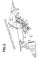
- FIG. 2 shows this same assembly in a similar manner but according to a more representative version of a practical embodiment.
- the same elements are represented there with the same references.
- the combination item 5 made up by the association of two half-cubes, the diagonal face separating them being treated partially transparent so as to transmit the image 11 of the tube 1 and reflect the image 12 coming from the tube 2
- One of the half-cubes is applied by one face to the screen of the monochrome cathode ray tube 1.
- the relay objective 4 produces the intermediate image 120 on the symmetrical face of the other half cube.
- the collimator optic is formed in two parts, a first part 2A located between the combination optic 5 and the reflecting mirror 7 and a second part 2B downstream of the mirror 8.
- the optics 2A and 2B have the axis direction optical axes Z1 and Z3 respectively. This division of collimator optics facilitates the installation of head-down displays.
- the intermediate image 120 is a reduced image of that 12 formed by the color tube with mask 3.
- the collimator objective 2A,. 2B performs the optical conjugation between the pupil of the relay lens 4 and the eye of the observer placed at the observation point O, so as to minimize the volume of the relay optics and so that the light rays entering the optics 4 are projected in the vicinity of the eyes and are not intercepted by the edges of the optics 2A, 2B, limiting as much as possible the vignetting (part of the light beams stopped by the edges of the lenses) of the image on the color channel .
- Additional control means are provided for controlling the desired start-up of the head-up and / or head-down display devices. These control means are symbolized in FIG. 1 by a block 20 which can develop control signals S1, S2 and possibly S3 for a head-up display. These signals ensure the commissioning of the corresponding image generators, by applying very high voltage supply voltages for example.
- the monochrome image presents multiple operational applications such as the vision of the landscape under the nose of the aircraft to facilitate landing or deck landing, in continuity with the head-up display; vision of a night landscape in the case of an infrared image by a FLIR or equivalent device, television tracking in a lens designation system by laser, etc.
- a filter 21 can be placed downstream of the optics 2B on the path going to the observer to attenuate the stray reflections coming from the outside. It can be a directional filter, for example a microvolette, or a spectral or interference filter.
Landscapes
- Physics & Mathematics (AREA)
- General Physics & Mathematics (AREA)
- Optics & Photonics (AREA)
Claims (8)
Applications Claiming Priority (2)
| Application Number | Priority Date | Filing Date | Title |
|---|---|---|---|
| FR8503083A FR2578330B1 (fr) | 1985-03-01 | 1985-03-01 | Systeme aeroporte de visualisation d'images collimatees |
| FR8503083 | 1985-03-01 |
Publications (2)
| Publication Number | Publication Date |
|---|---|
| EP0194196A1 EP0194196A1 (de) | 1986-09-10 |
| EP0194196B1 true EP0194196B1 (de) | 1989-05-31 |
Family
ID=9316796
Family Applications (1)
| Application Number | Title | Priority Date | Filing Date |
|---|---|---|---|
| EP86400405A Expired EP0194196B1 (de) | 1985-03-01 | 1986-02-25 | Einspiegelungssichtgerät für Flugzeuge |
Country Status (4)
| Country | Link |
|---|---|
| US (1) | US4697879A (de) |
| EP (1) | EP0194196B1 (de) |
| DE (1) | DE3663748D1 (de) |
| FR (1) | FR2578330B1 (de) |
Families Citing this family (30)
| Publication number | Priority date | Publication date | Assignee | Title |
|---|---|---|---|---|
| AU590835B2 (en) * | 1986-03-31 | 1989-11-16 | Dainippon Printing Co. Ltd. | Integrated head-up and panel display unit |
| FR2611926B1 (fr) * | 1987-03-03 | 1989-05-26 | Thomson Csf | Dispositif de visualisation collimatee en relief |
| FR2613845B1 (fr) * | 1987-04-10 | 1993-09-17 | Thomson Csf | Dispositif de visualisation d'informations lumineuses par projection sur une paroi transparente et son utilisation pour la navigation aerienne |
| GB8719854D0 (en) * | 1987-08-21 | 1987-09-30 | Secr Defence | Optical system |
| US5278532A (en) * | 1987-09-14 | 1994-01-11 | Hughes Aircraft Company | Automotive instrument virtual image display |
| US5400045A (en) * | 1988-04-01 | 1995-03-21 | Yazaki Corporation | Indication display unit for a vehicle |
| US5050966A (en) * | 1988-07-06 | 1991-09-24 | Kaiser Aerospace & Electronics Corporation | Optical combiner collimating apparatus |
| US5406299A (en) * | 1989-05-30 | 1995-04-11 | The United States Of America As Represented By The Secretary Of The Air Force | Hybrid field-sequential display |
| US5013135A (en) * | 1989-07-10 | 1991-05-07 | Matsushita Electric Industrial Co., Ltd. | Head-up display with two fresnel lenses |
| US5270682A (en) * | 1989-12-13 | 1993-12-14 | Yazaki Corporation | Display devices of the reflection type for vehicle |
| US5121099A (en) * | 1990-08-31 | 1992-06-09 | Hughes Aircraft Company | Two-page automotive virtual image display |
| IT1246064B (it) * | 1991-04-24 | 1994-11-07 | Veglia Borletti Srl | Apparato per la visualizzazione di dati in un veicolo |
| US5534694A (en) * | 1992-06-04 | 1996-07-09 | Hughes Electronics | Infrared imaging system for enhancing the perception of a scene by a vehicle operator |
| FR2703792B1 (fr) * | 1993-04-09 | 1995-05-19 | Sextant Avionique | Dispositif de contrôle de la position et de l'orientation d'un miroir. |
| GB9318520D0 (en) * | 1993-09-07 | 1993-10-20 | Jaguar Cars | Head up displays for motor vehicles |
| FR2717914B1 (fr) * | 1994-03-25 | 1996-05-31 | Sextant Avionique | Dispositif de rangement d'une glace holographique notamment pour aéronefs. |
| FR2742636B1 (fr) * | 1995-12-26 | 1998-02-06 | Sextant Avionique | Casque a dispositif de vision nocturne a securite et ergonomie optimisees |
| AU5156198A (en) * | 1996-10-29 | 1998-05-22 | Xeotron Corporation | Optical device utilizing optical waveguides and mechanical light-switches |
| JP2001506772A (ja) | 1996-12-20 | 2001-05-22 | シーメンス アクチエンゲゼルシヤフト | 少なくとも一人のための情報表示システム |
| US7280134B1 (en) | 1998-01-26 | 2007-10-09 | Thales Avionics, Inc. | Landscape camera system with electronic field of view switching |
| US6952312B2 (en) * | 2002-12-31 | 2005-10-04 | 3M Innovative Properties Company | Head-up display with polarized light source and wide-angle p-polarization reflective polarizer |
| DE102005043159A1 (de) * | 2005-09-12 | 2007-03-15 | Robert Bosch Gmbh | Einrichtung zur Darstellung eines Bildes im Blickfeld eines Fahrzeugführers |
| EP1798587B1 (de) * | 2005-12-15 | 2012-06-13 | Saab Ab | Head-Up-Anzeige |
| US20070279755A1 (en) * | 2006-06-01 | 2007-12-06 | 3M Innovative Properties Company | Head-Up Display System |
| FR2916541B1 (fr) * | 2007-05-25 | 2014-11-21 | Thales Sa | Dispositif de visualisation tete haute pour aeronef comprenant des moyens d'affichage d'une symbologie dediee a l'evitement d'obstacles. |
| FR2952441B1 (fr) | 2009-11-11 | 2016-11-25 | Johnson Controls Tech Co | Dispositif d'affichage, notamment pour vehicule automobile |
| KR101500399B1 (ko) * | 2013-12-02 | 2015-03-09 | 현대자동차 주식회사 | 리어 콤비네이션 램프 기능을 제공하는 곡면 디스플레이 장치 |
| KR101518932B1 (ko) * | 2013-12-18 | 2015-05-11 | 현대자동차 주식회사 | 차량용 디스플레이 장치 |
| JP6252203B2 (ja) * | 2014-01-23 | 2017-12-27 | 日本精機株式会社 | 表示装置 |
| CN103869472B (zh) * | 2014-04-11 | 2016-01-06 | 成都西麦克虚拟现实电子技术有限公司 | 平视显示系统及其平视显示方法 |
Family Cites Families (11)
| Publication number | Priority date | Publication date | Assignee | Title |
|---|---|---|---|---|
| GB1031379A (en) * | 1962-06-29 | 1966-06-02 | Ferranti Ltd | Improvements relating to navigation systems |
| GB1297139A (de) * | 1969-07-03 | 1972-11-22 | ||
| US3885095A (en) * | 1973-04-30 | 1975-05-20 | Hughes Aircraft Co | Combined head-up multisensor display |
| SE389745B (sv) * | 1973-05-31 | 1976-11-15 | S M Ellis | Presentationsenhet |
| DE2521874A1 (de) * | 1975-05-16 | 1976-12-02 | Siemens Ag | Vorrichtung zur ueberlagerung von schirmbildern mit hintergrundinformation |
| FR2391109A1 (fr) * | 1977-05-17 | 1978-12-15 | Thomson Csf | Collimateur de pilotage |
| GB2006981A (en) * | 1977-10-19 | 1979-05-10 | Elliott Bros | Head-up display |
| US4264134A (en) * | 1978-05-26 | 1981-04-28 | Elliott Brothers (London) Limited | Display arrangements |
| IN152994B (de) * | 1978-09-15 | 1984-05-19 | Elliott Brothers London Ltd | |
| DE3070141D1 (en) * | 1979-05-16 | 1985-03-28 | Pilkington Perkin Elmer Ltd | Four-component lens and display apparatus including this lens |
| DE3103045A1 (de) * | 1981-01-30 | 1982-08-26 | Teldix Gmbh | Einspiegelungssichtgeraet |
-
1985
- 1985-03-01 FR FR8503083A patent/FR2578330B1/fr not_active Expired
-
1986
- 1986-02-25 EP EP86400405A patent/EP0194196B1/de not_active Expired
- 1986-02-25 DE DE8686400405T patent/DE3663748D1/de not_active Expired
- 1986-03-03 US US06/835,340 patent/US4697879A/en not_active Expired - Lifetime
Also Published As
| Publication number | Publication date |
|---|---|
| US4697879A (en) | 1987-10-06 |
| FR2578330B1 (fr) | 1989-03-31 |
| EP0194196A1 (de) | 1986-09-10 |
| FR2578330A1 (fr) | 1986-09-05 |
| DE3663748D1 (en) | 1989-07-06 |
Similar Documents
| Publication | Publication Date | Title |
|---|---|---|
| EP0194196B1 (de) | Einspiegelungssichtgerät für Flugzeuge | |
| EP1798587B1 (de) | Head-Up-Anzeige | |
| US4714320A (en) | Display systems | |
| EP0365406B1 (de) | Optisches Kollimationssystem für eine Helmsichtanzeige | |
| US7619825B1 (en) | Compact head up display with wide viewing angle | |
| EP0433145B1 (de) | Optische Einrichtung zur Darstellung von Sichtdaten im Unendlichen | |
| EP0305096B1 (de) | Optische Anordnung für Head-up-Displays | |
| US20080143639A1 (en) | Helmet-mounted display system with interchangeable optical modules | |
| US3936148A (en) | Head-up display units and optical devices | |
| US9470891B2 (en) | Head-up display for night vision goggles | |
| FR2732479A1 (fr) | Dispositif de visualisation tete haute, de type holographique a optique relais simplifiee | |
| US3738733A (en) | Optical display systems | |
| US10409077B2 (en) | Distributed aperture head up display (HUD) | |
| EP0990188B1 (de) | Bilddarstellungsvorrichtung für helmanzeige | |
| GB2182456A (en) | Display systems | |
| US11061370B2 (en) | Viewing system including a holographic optical device allowing images to be displayed in different planes | |
| US7636199B2 (en) | Optical device for superposing electronic images in front of an objective | |
| FR3115894A1 (fr) | Appareil de projection d’images et unité de pilotage associée | |
| US3666346A (en) | Headsup display with remote recorder | |
| Cameron | Development of the combiner-eyepiece night-vision goggle | |
| EP0635743A1 (de) | Binokulares optisches Gerät mit erhöhter Auflösung und/oder vergrösserten Blichfeld, insbesondere für Nachtsicht (Gerät) | |
| FR2665962A1 (fr) | Systeme optique large champ et grande ouverture notamment destine a une voie de nuit pour episcope, et episcope equipe d'un tel systeme optique. | |
| SE439070B (sv) | Optisk presentationsanordning | |
| Banbury | Wide field of view head-up displays | |
| CZ35692U1 (cs) | Průhledový displej pro letadlo |
Legal Events
| Date | Code | Title | Description |
|---|---|---|---|
| PUAI | Public reference made under article 153(3) epc to a published international application that has entered the european phase |
Free format text: ORIGINAL CODE: 0009012 |
|
| AK | Designated contracting states |
Kind code of ref document: A1 Designated state(s): DE GB SE |
|
| 17P | Request for examination filed |
Effective date: 19861217 |
|
| 17Q | First examination report despatched |
Effective date: 19880704 |
|
| GRAA | (expected) grant |
Free format text: ORIGINAL CODE: 0009210 |
|
| RAP3 | Party data changed (applicant data changed or rights of an application transferred) |
Owner name: THOMSON-CSF |
|
| AK | Designated contracting states |
Kind code of ref document: B1 Designated state(s): DE GB SE |
|
| REF | Corresponds to: |
Ref document number: 3663748 Country of ref document: DE Date of ref document: 19890706 |
|
| GBT | Gb: translation of ep patent filed (gb section 77(6)(a)/1977) | ||
| PLBE | No opposition filed within time limit |
Free format text: ORIGINAL CODE: 0009261 |
|
| STAA | Information on the status of an ep patent application or granted ep patent |
Free format text: STATUS: NO OPPOSITION FILED WITHIN TIME LIMIT |
|
| 26N | No opposition filed | ||
| EAL | Se: european patent in force in sweden |
Ref document number: 86400405.6 |
|
| PGFP | Annual fee paid to national office [announced via postgrant information from national office to epo] |
Ref country code: SE Payment date: 20000117 Year of fee payment: 15 |
|
| PGFP | Annual fee paid to national office [announced via postgrant information from national office to epo] |
Ref country code: GB Payment date: 20000119 Year of fee payment: 15 |
|
| PGFP | Annual fee paid to national office [announced via postgrant information from national office to epo] |
Ref country code: DE Payment date: 20000211 Year of fee payment: 15 |
|
| PG25 | Lapsed in a contracting state [announced via postgrant information from national office to epo] |
Ref country code: GB Free format text: LAPSE BECAUSE OF NON-PAYMENT OF DUE FEES Effective date: 20010225 |
|
| PG25 | Lapsed in a contracting state [announced via postgrant information from national office to epo] |
Ref country code: SE Free format text: LAPSE BECAUSE OF NON-PAYMENT OF DUE FEES Effective date: 20010226 |
|
| EUG | Se: european patent has lapsed |
Ref document number: 86400405.6 |
|
| GBPC | Gb: european patent ceased through non-payment of renewal fee |
Effective date: 20010225 |
|
| PG25 | Lapsed in a contracting state [announced via postgrant information from national office to epo] |
Ref country code: DE Free format text: LAPSE BECAUSE OF NON-PAYMENT OF DUE FEES Effective date: 20011201 |